Silica hybrid particles with nanometre polymer shells and their influence on the toughening of polypropylene
Jing-Zhi
Zheng
a,
Xing-Ping
Zhou
a,
Xiao-Lin
Xie
*a and
Yiu-Wing
Mai
*b
aState Key Laboratory of Material Processing and Die & Mould Technology, School of Chemistry and Chemical Engineering, Huazhong University of Science and Technology, Wuhan 430074, China. E-mail: xlxie@mail.hust.edu.cn; Tel: +86-27-87540053
bCentre for Advanced Materials Technology (CAMT), School of Aerospace, Mechanical and Mechatronic Engineering J07, University of Sydney, Sydney, NSW 2006, Australia. E-mail: yiu-wing.mai@sydney.edu.au; Tel: +61-2-9351-2290
First published on 21st August 2010
Abstract
Colloidal silica particles were synthesized by the sol–gel process and then modified with 3-methacryloxypropyltrimethoxysilane (γ-MPS) to induce vinyl groups on the surface of the silica particles. By means of in situ emulsion copolymerization of methyl methacrylate (MMA) and butyl acrylate (BA), a series of core–shell silica hybrid particles with nanometre poly(MMA-co-BA) shells were fabricated, which were subsequently compounded with isotactic polypropylene (PP) in the molten state. Upon increasing the feed silica![[hair space]](https://www.rsc.org/images/entities/char_200a.gif) :
:![[hair space]](https://www.rsc.org/images/entities/char_200a.gif) monomer ratio from 1
monomer ratio from 1![[hair space]](https://www.rsc.org/images/entities/char_200a.gif) :
:![[hair space]](https://www.rsc.org/images/entities/char_200a.gif) 1 to 4
1 to 4![[hair space]](https://www.rsc.org/images/entities/char_200a.gif) :
:![[hair space]](https://www.rsc.org/images/entities/char_200a.gif) 1, the poly(MMA-co-BA) shell thickness on the silica core decreased from 50 nm to 10 nm. Owing to the existence of the nanometre poly(MMA-co-BA) shells, the silica hybrid particles were monodispersed in the PP matrix, causing homogeneous debonding at the PP/silica interface, followed by plastic void expansion and matrix shear yielding during impact fracture. These deformation mechanisms greatly toughened the PP–silica composites. A critical shell thickness of poly(MMA-co-BA) was needed to achieve optimal mechanical properties. That is, when the polymer shell thickness was 15 nm, compared to pure PP, the impact toughness of the PP–silica composite was more than doubled with little degradation of tensile strength.
1, the poly(MMA-co-BA) shell thickness on the silica core decreased from 50 nm to 10 nm. Owing to the existence of the nanometre poly(MMA-co-BA) shells, the silica hybrid particles were monodispersed in the PP matrix, causing homogeneous debonding at the PP/silica interface, followed by plastic void expansion and matrix shear yielding during impact fracture. These deformation mechanisms greatly toughened the PP–silica composites. A critical shell thickness of poly(MMA-co-BA) was needed to achieve optimal mechanical properties. That is, when the polymer shell thickness was 15 nm, compared to pure PP, the impact toughness of the PP–silica composite was more than doubled with little degradation of tensile strength.
Introduction
Polymer–inorganic particle composites, especially nanocomposites, have attracted more and more attention owing to their excellent processability, unique mechanical, optical, electric and magnetic properties.1–3 Among the many polymer–matrix composites, ultrafine silica particles, including micro- and nanosized silica, have been employed in a variety of applications because of their optical transparency, electrical insulation, biocompatibility, chemical and thermal resistance, mechanical stability, variable sizes, tunable surface properties and low costs.4–6 The greatest challenge to their large-scale production and commercialization is achieving homogeneous dispersion of the ultrafine particles in a polymer matrix.7–9In situ polymerization is often used to prepare ultrafine particle-filled composites with good dispersion.10–12 However, the method is unsuitable for polyolefin–matrix composites due to the low catalytic activity of the Ziegler–Natta catalyst supported on ultrafine particles and low conversion of the monomer.13,14 It is well known that melt compounding is still the most convenient technique for fabricating polymer composites.15,16 Thus, many attempts have been made to modify the surfaces of ultrafine particles to prepare composites with a homogeneous dispersion. For example, Castrillo et al. improved the dispersion of nanosilica in a poly(methyl methacrylate) (PMMA) matrix by high-energy ball-milling.17 Dispersing aids and compatibilizers, such as epoxy18 and maleic anhydride-grafted polypropylene (PP-g-MA),19 have been used to improve the dispersion of nanosilica in a polypropylene (PP) matrix. Rong et al.16,20 and Reddy and Das21 enhanced the dispersion of nanosized silica in PP by modifying the silica surface via grafting of a vinyl monomer and an epoxy, respectively. Saujanya and Radhakrishnan22 improved dispersion of nanosized calcium phosphate in a PP matrix by coating poly(ethylene oxide) on the surface of the nanoparticles. Xie and co-workers9,23–26 modified inorganic ultrafine particles, e.g., talc, glass beads, hydroxyapatite, antimony trioxide, etc. by polymerization of a particular monomer. This technique is called in situ monomer–inorganic particle polymerization. As the polymer of the selected monomer is miscible or compatible with the composite matrix, the polymer shells formed on the ultrafine particles promote dispersion in the matrix. In recent work on nanocomposites based on PP and nanosilica particles modified by in situ copolymerization of methyl methacrylate (MMA) and butyl acrylate (BA) with a 1![[hair space]](https://www.rsc.org/images/entities/char_200a.gif) :
:![[hair space]](https://www.rsc.org/images/entities/char_200a.gif) 1 weight ratio, Zheng et al.27 showed that these nanocomposites have balanced stiffness and toughness due to the moderate elastic modulus and solubility parameter of the poly(MMA-co-BA) copolymer compared to PMMA and PBA. However, the modified ultrafine particles are not monodispersed in the composites upon melt compounding.
1 weight ratio, Zheng et al.27 showed that these nanocomposites have balanced stiffness and toughness due to the moderate elastic modulus and solubility parameter of the poly(MMA-co-BA) copolymer compared to PMMA and PBA. However, the modified ultrafine particles are not monodispersed in the composites upon melt compounding.
Recently, a sol–gel process combined with polymerization of monomers was used to fabricate polymer-based composites with uniform particle dispersion.28–31 Monodispersed core–shell silica particles covered with polymer chains were successfully synthesized.6,32–35 Sun et al.36 prepared PP–silica nanocomposites by in situ sol–gel reaction with the aid of carbon dioxide. To the best of our knowledge, there is no report on fabricating monodispersed polymer–sol–gel silica composites by melt compounding. Here, a series of core–shell silica hybrid particles with poly(MMA-co-BA) shells were synthesized through in situ emulsion copolymerization of MMA and BA, then melt compounded with isotatic PP to prepare PP–silica composites. The main goal of the present research was to study the effect of interface characteristics on the mechanical properties of PP–silica composites by adjusting the polymer shell thickness on the silica particles.
Experiment and methods
3-Methacryloxypropyltrimethoxysilane (γ-MPS) was supplied by Organic Silicon Company, Wuhan University, China. Tetraethyl orthosilicate (TEOS) was purchased from Shanghai Chemistry Agent Company, China. Analytical grade methyl methacrylate (MMA) and butyl acrylate (BA) were also obtained from this company and were purified by distillation under reduced pressure before use. Polypropylene (PP) (T36f) with anti-oxidant 1010 (i.e., pentaerythritol tetrakis [3-(3′,5′-di-tert-butyl-4′-hydroxyphenyl) propionate]) was provided by Wuhan Petrochemical Company, China. All other materials were analytical grade and commercially available.Synthesis of core–shell silica hybrid particles
Colloidal silica particles were prepared by sol–gel reaction according to the method used by Stöber et al.37 First, 600 mL absolute ethanol, 100 mL distilled water and 40 mL TEOS were mixed in a 1000 mL three-neck round-bottom flask. Then 28 mL of 26% ammonia water was added to the mixture and stirred for 24 h at room temperature.To introduce vinyl groups on the surface of the silica particles, 10 mL of γ-MPS was added to the above suspension and stirred for 24 h at ambient temperature. Three cycles of centrifugation and washing with ethanol were used to remove the excess γ-MPS. Then, the final vinylated silica particles were dried in a vacuum at low temperature for 12 h.
According to ref. 38, core–shell silica hybrid particles were prepared by in situ emulsion copolymerization. The feed ratios of the silica and comonomers were 1![[hair space]](https://www.rsc.org/images/entities/char_200a.gif) :
:![[hair space]](https://www.rsc.org/images/entities/char_200a.gif) 0, 1
0, 1![[hair space]](https://www.rsc.org/images/entities/char_200a.gif) :
:![[hair space]](https://www.rsc.org/images/entities/char_200a.gif) 1, 2
1, 2![[hair space]](https://www.rsc.org/images/entities/char_200a.gif) :
:![[hair space]](https://www.rsc.org/images/entities/char_200a.gif) 1 and 4
1 and 4![[hair space]](https://www.rsc.org/images/entities/char_200a.gif) :
:![[hair space]](https://www.rsc.org/images/entities/char_200a.gif) 1; the final silica hybrid particles were designated Si, Si-1, Si-2 and Si-3, respectively. 10 g vinylated silica particles, 0.25 g emulsifier (sodium dodecyl sulfate, SDS), 0.25 g sodium bicarbonate and 250 g deionized water were placed in a 500 mL four-necked flask with a mechanical stirrer (with a fixed stirring rate of 150 rpm), thermometer, condenser, in a nitrogen atmosphere and the flask was placed in a 40 kHz ultrasonic water bath. After the mixture was heated to 70 °C, the potassium persulfate (KPS) was divided into four equal parts by weight, and added into the flask in 0.75 h intervals. The mixture of MMA and BA (1
1; the final silica hybrid particles were designated Si, Si-1, Si-2 and Si-3, respectively. 10 g vinylated silica particles, 0.25 g emulsifier (sodium dodecyl sulfate, SDS), 0.25 g sodium bicarbonate and 250 g deionized water were placed in a 500 mL four-necked flask with a mechanical stirrer (with a fixed stirring rate of 150 rpm), thermometer, condenser, in a nitrogen atmosphere and the flask was placed in a 40 kHz ultrasonic water bath. After the mixture was heated to 70 °C, the potassium persulfate (KPS) was divided into four equal parts by weight, and added into the flask in 0.75 h intervals. The mixture of MMA and BA (1![[hair space]](https://www.rsc.org/images/entities/char_200a.gif) :
:![[hair space]](https://www.rsc.org/images/entities/char_200a.gif) 1 by weight) was added dropwise at a rate of 0.5 mL h−1. After 8 h, the mini-emulsion was centrifuged at 6000 rpm and washed with water and ethanol, respectively, for three cycles to remove SDS, unreacted monomer and free poly(MMA-co-BA) copolymer. Finally, the prepared silica hybrid particles were dried at 60 °C in a vacuum. Poly(MMA-co-BA) copolymers were also synthesized using the above procedure.
1 by weight) was added dropwise at a rate of 0.5 mL h−1. After 8 h, the mini-emulsion was centrifuged at 6000 rpm and washed with water and ethanol, respectively, for three cycles to remove SDS, unreacted monomer and free poly(MMA-co-BA) copolymer. Finally, the prepared silica hybrid particles were dried at 60 °C in a vacuum. Poly(MMA-co-BA) copolymers were also synthesized using the above procedure.
Preparation of PP–silica composites
Pristine sol–gel silica particles and silica hybrid particles were each compounded with PP in the mixer of a Haake rheometer 600 at 200 °C and 50 rpm for 10 min. The silica weight fraction (Wf) was kept at 5 wt%. As controls, 2.5% of poly(MMA-co-BA) copolymers were blended with PP to fabricate the PP–poly(MMA-co-BA) blend under identical conditions. Tensile and impact samples were injection-moulded with a barrel temperature of 200 °C.Characterization and testing
Fourier-transform infrared (FTIR) spectroscopy was employed to characterize changes in the chemical structure of pristine, vinylated silica and hybrid particles using a VERTEX 70 spectrometer (Bruker, Germany). Specimens were extracted with toluene for 24 h using a Soxhlet apparatus, dried and pressed with KBr powder. Thermal gravimetric analysis (TGA) was conducted using Diamond TG/DTA instruments (Perkin Elmer, USA) under air flow (50 ml min−1) at 10 °C min−1. To determine the molecular weight of the poly(MMA-co-BA) on silica, these silica hybrid particles were dissolved in hydrofluoric acid and the resultant mixture was added to toluene. The upper transparent toluene solution was then poured into ethanol to obtain the separated poly(MMA-co-BA), whose molecular weight was measured by size-exclusion chromatography (SEC, Aligent 1100 HPLC, USA) equipped with a 79911GP-MXC column and an RI detector at 25 °C in tetrahydrofuran solution at an elution rate of 1.0 mL min−1 against polystyrene standards. The morphological structures of silica hybrid nanoparticles were examined with a Tecnai G2 20 transmission electron microscope (FEI, Netherlands).The morphologies of the PP–silica composites were observed using a JSM-5510 LV scanning electron microscope (Japan) on cryo-fractured specimens after immersion in liquid nitrogen. All the surfaces were coated with a thin layer of gold prior to SEM examination. Tensile tests were performed using an Instron 4206 machine at 20 °C with a crosshead speed of 50 mm min−1. Izod notched impact toughness was measured with a Ceast pendulum impact tester at 20 °C. The results reported here represent the average values from five samples. Dynamic mechanical analysis (DMA) was also conducted on a TA Q800 Instrument dynamic mechanical analyzer at a fixed frequency of 10 Hz and an oscillation amplitude of 0.15 mm. The temperature range studied was from −60 to 130 °C with a heating rate of 3 °C min−1. The crystallization and melting behaviors of PP and PP–silica composites were measured by DSC using a Perkin-Elmer DSC-7 instrument at a heating rate of 10 °C min−1 in dry nitrogen. All specimens were heated to 220 °C and kept at this temperature for 3 min before quenching to ambient temperature to eliminate previous thermal histories. For non-isothermal crystallization measurements, the samples were heated to and remained at 220 °C for 3 min, and then cooled at a rate of 10 °C min−1.
Results and discussion
Structure of silica hybrid particles
Fig. 1 shows the FTIR spectra of pristine sol–gel silica, vinylated silica and the extracted silica hybrid particles. Curve (a) clearly shows a strong absorption band related to the Si–O stretching vibration in silica at 1096 cm−1 and a broad absorption band due to the hydroxyl groups on the surface of silica in the range 3750–3000 cm−1. After modification with γ-MPS (see curve (b)), new absorption bands, represented by the two red arrows, appear at 2930 cm−1 and 1430 cm−1, associated with vibrations due to stretching of the C–H group and bending of the methyl and methylene groups in MPS, respectively. The stretching vibration peaks of the C![[double bond, length as m-dash]](https://www.rsc.org/images/entities/char_e001.gif) O and C
O and C![[double bond, length as m-dash]](https://www.rsc.org/images/entities/char_e001.gif) C groups are very weak since their contents are low in vinylated silica. The results indicate that the hydroxyl groups on the silica surface react with the silanol groups generated by hydrolysis of the alkyloxyl group of γ-MPS through dehydration and condensation to form Si–O–Si bonds. Hence, the vinyl groups are covalently attached to the silica surface as given in scheme 1.
C groups are very weak since their contents are low in vinylated silica. The results indicate that the hydroxyl groups on the silica surface react with the silanol groups generated by hydrolysis of the alkyloxyl group of γ-MPS through dehydration and condensation to form Si–O–Si bonds. Hence, the vinyl groups are covalently attached to the silica surface as given in scheme 1.
 | ||
| Scheme 1 | ||
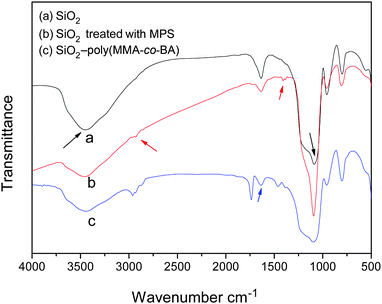 | ||
| Fig. 1 FTIR spectra of (a) pristine sol–gel silica, (b) vinylated silica, and (c) extracted hybrid particle. | ||
Also, the introduction of γ-MPS on the silica surface improves the hydrophobic properties of silica, which is beneficial for the formation of a stable emulsion with SDS. After being vinylated, the silica particles were further modified by in situ copolymerization of MMA and BA as shown in scheme 2.
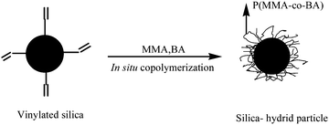 | ||
| Scheme 2 | ||
Clearly, there is a sharp C![[double bond, length as m-dash]](https://www.rsc.org/images/entities/char_e001.gif) O stretching peak at 1731 cm−1 (see curve (c)), which indicates that poly(MMA-co-BA) copolymers are successfully grafted onto the silica particles.
O stretching peak at 1731 cm−1 (see curve (c)), which indicates that poly(MMA-co-BA) copolymers are successfully grafted onto the silica particles.
Fig. 2 shows TGA curves for pristine sol–gel silica and hybrid particles. It can be seen that all have obvious weight losses (ca. 5 wt%) below 200 °C. Sertchook et al.39 and Ogawa et al.40 attributed this weight loss to the loss of absorbed water and dehydration of the residual silanol groups. To check these mechanisms, we studied the TGA behavior of pristine sol–gel silica where the temperature was increased to 200 °C, kept constant for 5 min, and cooled to ambient temperature. We found that the weight increased during cooling due to the adsorbed air but the values were slightly lower than during heating. So, we believe the weight loss seen in Fig. 2 is caused by the dehydration of residual silanol groups and release of absorbed water and air in the silica particles. Additionally, the pristine sol–gel silica particles are stable at high temperatures. Even at 800 °C the loss is only 9.2 wt%. However, silica hybrid particles have a sharp weight loss from 200 to 600 °C owing to the thermal oxidation and decomposition of the poly(MMA-co-BA) copolymers grafted onto the silica particles. Based on the residues at 800 °C, the grafting percentage values of poly(MMA-co-BA) on Si-1, Si-2 and Si-3 are 24.2, 16.8 and 12.3%, respectively. Hence, the grafted percentage of poly(MMA-co-BA) on silica decreases with increasing feed ratio of silica to comonomer.
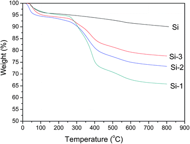 | ||
| Fig. 2 TGA curves for pristine silica (Si) and extracted hybrid particles (Si-1, Si-2, Si-3). | ||
Fig. 3 shows TEM images of pristine sol–gel silica and core–shell hybrid particles. Obviously, the average diameter of pristine sol–gel silica particles is ∼200 nm (see Fig. 3(a)). After the silica particles were modified by γ-MPS and in situ copolymerized with MMA and BA, these hybrid particles form a uniform monodispersed core–shell structure with one silica particle as the core and poly(MMA-co-BA) copolymers as the shell. For a feed ratio of silica to comonomer of 1![[hair space]](https://www.rsc.org/images/entities/char_200a.gif) :
:![[hair space]](https://www.rsc.org/images/entities/char_200a.gif) 1, the poly(MMA-co-BA) shell on Si-1 is ∼50 nm thick (see Fig. 3(b)). With decreasing comonomer content, the poly(MMA-co-BA) shell thicknesses decrease to 15 and 10 nm for Si-2 and Si-3, respectively (see Figs. 3(c) and (d)). It is noted that the average molecular weight of poly(MMA-co-BA) attached to Si-1 and Si-2 is roughly 1–6 × 10⁶ g mol−1 based on SEC, which indicates that the existence of silica does not affect the chain propagation during in situ copolymerization of MMA and BA.
1, the poly(MMA-co-BA) shell on Si-1 is ∼50 nm thick (see Fig. 3(b)). With decreasing comonomer content, the poly(MMA-co-BA) shell thicknesses decrease to 15 and 10 nm for Si-2 and Si-3, respectively (see Figs. 3(c) and (d)). It is noted that the average molecular weight of poly(MMA-co-BA) attached to Si-1 and Si-2 is roughly 1–6 × 10⁶ g mol−1 based on SEC, which indicates that the existence of silica does not affect the chain propagation during in situ copolymerization of MMA and BA.
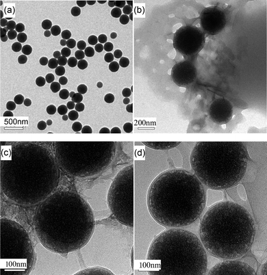 | ||
| Fig. 3 TEM images of pristine sol–gel silica and hybrid particles. (a) Si, (b) Si-1, (c) Si-2 and (d) Si-3 | ||
Mechanical properties and structure of PP–silica composites
Table 1 lists the mechanical properties of PP and PP–silica composites. It can be seen that the incorporation of sol–gel silica particles does not affect the tensile strength and impact toughness of PP. However, core–shell silica hybrid particles have a clear toughening effect on the PP matrix. For the PP–Si-1 composite, its impact toughness has increased to 5.01 kJ m−2 from 2.99 kJ m−2 for PP, whilst its tensile strength decreases to 36.7 MPa from 41.2 MPa. It is interesting to see that when the poly(MMA-co-BA) shells on the silica particles are decreased to 15 nm thick, both the tensile strength and impact toughness of the PP–Si-2 composite increase. With a further decrease in the poly(MMA-co-BA) shell thickness to 10 nm, the impact toughness value of the PP–Si-3 composite is reduced. In addition, the PP–poly(MMA-co-BA) blend has similar toughness but slightly lower tensile strength compared to the PP matrix. These results indicate that there is a critical poly(MMA-co-BA) shell thickness for the PP–silica composites to yield optimal strength and toughness properties. As the poly(MMA-co-BA) shell thickness exceeds the critical value (e.g., in PP–Si-1 with a shell thickness of ∼50 nm), the mechanical properties are reduced, possibly caused by the low tensile strength of poly(MMA-co-BA) and the internal stress in the poly(MMA-co-BA) interphase between PP and nanosilica particles arising from the different chemical and condensation structures of poly(MMA-co-BA) and PP. This behavior is akin to that observed for high impact polystyrene (HIPS)–hydroxyapatite (HA) and poly(vinyl chloride)–talc composites.23,26| Samples | Tensile yield strength/MPa | Impact toughness/kJ m−2 |
|---|---|---|
| PP | 41.2 | 2.99 |
| PP–Si | 41.7 | 2.91 |
| PP–Si-1 | 36.7 | 5.01 |
| PP–Si-2 | 40.0 | 6.14 |
| PP–Si-3 | 39.5 | 5.45 |
| PP–poly(MMA-co-BA) | 39.1 | 2.96 |
To understand the mechanical behavior of PP–Si-2, it is necessary to examine its structure compared with that of the PP–pristine sol–gel silica composite. Fig. 4 shows SEM images of impact-fractured PP–silica composites filled with pristine sol–gel silica, and Si-2. Obviously, the impact-fractured surface of the PP–Si-2 composite is rougher than that of the impact-fractured PP–Si composite (see Figs. 4(a) and (c)), which provides direct evidence that the toughness of the PP–Si-2 composite is higher than that of the PP–Si composite. Also, the pristine sol–gel silica (Si) particles are easily aggregated in the PP matrix (see Fig. 4(b)) due to the high surface energy of the Si particles, and the different surface properties of PP and Si. During impact fracture, the aggregated silica clusters are easily pulled out from the matrix. However, when the nanosilica particles are modified by γ-MPS, and followed with in situ copolymerization of MMA and BA, the poly(MMA-co-BA) shells on the silica cores serve as a compatibilizer enhancing the interaction between the PP matrix and the silica hybrid particles (Si-2), leading to uniform mono-dispersion of the Si-2 particles in PP and large interfacial areas with much improved PP–Si-2 adhesion. Comparing Fig. 4(d) to 4(b), debonding of the monodispersed Si-2 particles and the ensuing plastic void expansion of the PP matrix prevail at the fracture surface. These sites are marked with red circles. A predominant stress-whitened zone beneath the fracture surface of the PP–Si-2 composite owing to matrix shear yielding is also found. However, PP and PP–Si exhibit nil or negligible stress-whitened zones and hence have much lower toughness values compared to PP–Si-2 (see Table 1). Therefore, similar to the epoxy–nanosilica composites studied by Johnsen et al.,41 debonding of Si-1,-2,-3 particles, plastic void expansion and shear yielding of PP matrix are the major toughening mechanisms, resulting in the high impact toughness values obtained for PP–Si-1, PP–Si-2 and PP–Si-3 composites as shown in Table 1.
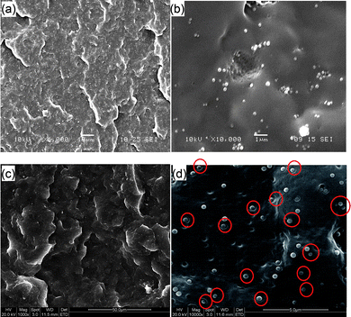 | ||
Fig. 4 SEM images of impact-fractured PP–silica composites. (a) Low- (×1000), and (b) high- (×10![[hair space]](https://www.rsc.org/images/entities/char_200a.gif) 000) magnification images of composites filled with pristine sol–gel silica. (c) Low- (×1000), and (d) high- (×10 000) magnification images of composites filled with pristine sol–gel silica. (c) Low- (×1000), and (d) high- (×10![[hair space]](https://www.rsc.org/images/entities/char_200a.gif) 000) magnification images of composites filled with Si-2. Red circles in (d) show typical PP/Si-2 interface debonding and plastic void expansion in the PP matrix. 000) magnification images of composites filled with Si-2. Red circles in (d) show typical PP/Si-2 interface debonding and plastic void expansion in the PP matrix. | ||
Fig. 5 shows the loss factor (tan δ) versus temperature for the PP, PP–Si and PP–Si-2 composites. It can be seen that the glass transition temperature (designated as Tg) of pure PP is 19.5 °C. The incorporation of sol–gel silica particles decreases Tg of PP phase in the PP–Si composite to 11.9 °C caused by the aggregation of silica particles.40 Generally, well-dispersed particles limit the mobility of polymer chain segments and increase the Tg of the matrix.42 But, the Tg of the PP phase in the PP–Si-2 composite is further decreased to 6.4 °C, even though the dispersion of Si particles in the PP–Si-2 composite is far better than that in the PP–Si composite. These results indicate that the poly(MMA-co-BA) shells on the Si-2 particles do not restrict the mobility of the PP chain segments. Instead, they plasticize the PP–silica composite and toughen the PP matrix.
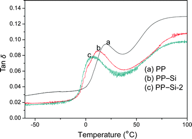 | ||
| Fig. 5 Variation of loss factor (tan δ) with temperature for PP, PP–Si and PP–Si-2 composites. | ||
Fig. 6 displays the cooling and melting DSC curves for the PP, PP–Si and PP–Si-2 composites. Their crystallization peak temperature (Tcp), melting peak temperature (Tmp) and melting enthalpy (ΔHm) were determined from the DSC thermograms and are listed in Table 2. Assuming the melting enthalpy of 100% crystalline PP is 237 J g−1,43 their degree of crystallinity (Xc) was also calculated and is shown in Table 2. Compared to pure PP, the pristine sol–gel silica particles act as nucleation sites to increase the Tcp of the PP phase in the PP–Si composite from 110.5 °C to 120.0 °C. The incorporation of well-dispersed Si-2 particles further increases the Tcp of the PP phase in the PP–Si-2 composite to 123.0 °C. However, addition of silica particles destroys the packing regularity of the PP chains during crystallization, leading to lower Tmp and Xc than those of pure PP.
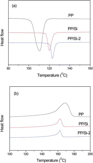 | ||
| Fig. 6 (a) Cooling and (b) heating DSC curves for the PP, PP–Si and PP–Si-2 composites. | ||
Finally, to examine the effect of the incorporation of pristine and surface-modified silica particles on the thermal stability of PP, Fig. 7 shows the TGA curves for the PP, PP–Si and PP–Si-2 composites. Their temperature of 5% weight loss (T5%) and residue values at 500 °C (W500) are listed in Table 2. Clearly, PP–Si and PP–Si-2 composites have the same thermal stability as pure PP. This means that the addition of pristine and modified silica particles does not affect the thermal stability of the PP matrix.
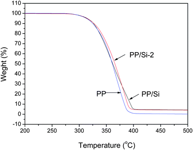 | ||
| Fig. 7 TGA curves for PP, PP–Si and PP–Si-2 composites. | ||
Conclusions
Silica-core particles with nanometre thick poly(MMA-co-BA) shells were successfully synthesized using a sol–gel process, modification with γ-MPS and in situ copolymerization of MMA and BA; the shell thickness can be adjusted via the feed-silica-to-comonomer ratio. The silica hybrid particles are monodispersed in the PP matrix owing to the nanometre poly(MMA-co-BA) shells. Particle debonding, plastic void expansion and matrix shear deformation are major energy absorption mechanisms during impact fracture giving rise to high toughness values for these PP-based composites. A critical shell thickness of 15 nm is required to maximize the impact toughness of the PP–silica composites, with negligible loss of tensile strength.Acknowledgements
We acknowledge financial support from the Outstanding Young Scholar Funding of the National Natural Science Foundation of China (50825301), and the Open Fund of the State Key Laboratory of Material Processing and Die & Mould Technology of HUST. We also thank the Analytical and Testing Center of HUST for access to facilities required for this work. YWM is grateful to the Australian Research Council for continuing support of his research on polymer composites.References
- J. E. Mark, Polym. Eng. Sci., 1996, 36, 2905 CrossRef CAS.
- D. D. L. Chung, Composite Materials: Functional Materials for Modern Technologies, Springer-Verlag, London, 2003 Search PubMed.
- Y.-W. Mai and Z.-Z. Yu, Polymer Nanocomposites, CRC Press, Woodhead Publishing Limited, Cambridge, England, 2006 Search PubMed.
- R. Duchateau, Chem. Rev., 2002, 102, 3525–3542 CrossRef CAS.
- H. Zou, S. Wu and J. Shen, Chem. Rev., 2008, 108, 3893 CrossRef CAS.
- Y. K. Yang, Z. F. Yang, Q. Zhao, X. J. Cheng, S. C. Tjong, R. K. Y. Li, X. T. Wang and X. L. Xie, J. Polym. Sci., Part A: Polym. Chem., 2009, 47, 467 CrossRef CAS.
- V. Viswanathan, T. Laha, K. Balani, A. Agarwal and S. HSeal, Mater. Sci. Eng., R, 2006, 54, 121 CrossRef.
- L. A. Utracki, J. Nanosci. Nanotechnol., 2008, 8, 1582–1596 CrossRef CAS.
- X. L. Xie, R. K. Y. Li, Q. X. Liu and Y.-W. Mai, Polymer, 2004, 45, 2793 CrossRef CAS.
- Y. C. Ou, F. Yang and Z.-Z. Yu, J. Polym. Sci., Part B: Polym. Phys., 1998, 36, 789 CrossRef CAS.
- X. L. Xie, Q. X. Liu, R. K. Y. Li, X. P. Zhou, Q. X. Zhang, Z. Z. Yu and Y.-W. Mai, Polymer, 2004, 45, 6665 CrossRef CAS.
- R. Palkovits, H. Althues, A. Rumplecker, B. Tesche, A. Dreier, U. Holle, G. Fink, C. H. Cheng, D. F. Shantz and S. Kaskel, Langmuir, 2005, 21, 6048 CrossRef CAS.
- R. Krishnamoorti and R. A. Vaia, Polymer Nanocomposites, American Chemical Society, Washington DC, 2001 Search PubMed.
- W. Kaminsky, A. Funck and K. Wiemann, Macromol. Symp., 2006, 239, 1 CrossRef CAS.
- C. M. Chan, J. S. Wu, J. X. Li and Y. K. Cheung, Polymer, 2002, 43, 2981 CrossRef CAS.
- M. Z. Rong, M. Q. Zhang, Y. X. Zheng, R. Walter and K. Friedrich, Polymer, 2001, 42, 167 CrossRef CAS.
- P. D. Castrillo, D. Olmos, D. R. Amador and J. Gonzalez-Benito, J. Colloid Interface Sci., 2007, 308, 318 CrossRef CAS.
- P. B. Leng, H. M. Akil and O. H. Lin, J. Reinf. Plast. Compos., 2007, 26, 761 CrossRef CAS.
- D. N. Bikiaris, A. Vassiliou, E. Pavlidou and G. P. Karayannidis, Eur. Polym. J., 2005, 41, 1965 CrossRef CAS.
- M. Z. Rong, M. Q. Zhang, Y. X. Zheng and K. Friedrich, Polymer, 2001, 42, 3301 CrossRef CAS.
- C. S. Reddy and C. K. Das, J. Appl. Polym. Sci., 2006, 102, 2117 CrossRef CAS.
- C. Saujanya and S. Radhakrishnan, Polymer, 2001, 42, 6723 CrossRef CAS.
- X. L. Xie, B. G. Li, Z. R. Pan, R. K. Y. Li and S. C. Tjong, J. Appl. Polym. Sci., 2001, 80, 2105 CrossRef CAS.
- X. H. Gong, C. Y. Tang, H. C. Hu, X. P. Zhou and X. L. Xie, J. Mater. Sci.: Mater. Med., 2004, 15, 1141 CrossRef CAS.
- X. L. Xie, C. Y. Tang, X. P. Zhou, R. K. Y. Li, Z. Z. Yu, Q. X. Zhang and Y.-W. Mai, Chem. Mater., 2004, 16, 133 CrossRef CAS.
- X. H. Gong, X. L. Xie, C. Y. Tang and Y.-W. Mai, Compos. Interfaces, 2007, 14, 335 Search PubMed.
- J. Z. Zheng, X. P. Zhou, J. R. Ying, X. L. Xie and Y.-W. Mai, Chin. J. Polym. Sci., 2009, 27, 685 CrossRef CAS.
- G. Schottner, Chem. Mater., 2001, 13, 3422 CrossRef CAS.
- L. Matejka, O. Dukh and J. Kolarik, Polymer, 2000, 41, 1449 CrossRef CAS.
- H. Zhang, L. C. Tang, Z. Zhang, K. Friedrich and S. Sprenger, Polymer, 2008, 49, 3816 CrossRef CAS.
- S. Li, A. Shah, A. J. Hsieh, H. R. Haghighat, S. S. Praveen, I. Mukherjee, E. Wei, Z. Zhang and Y. Wei, Polymer, 2007, 48, 3982 CrossRef CAS.
- K. Zhang, H. Chen, X. Chen, Z. Chen, Z. Cui and B. Yang, Macromol. Mater. Eng., 2003, 288, 380 CrossRef CAS.
- S. W. Zhang, S. X. Zhou, Y. M. Weng and L. M. Wu, Langmuir, 2005, 21, 2124 CrossRef CAS.
- K. Ohno, T. Morinaga, K. Koh, Y. Tsujii and T. Fukuda, Macromolecules, 2005, 38, 2137 CrossRef CAS.
- D. M. Qi, Y. Z. Bao, Z. X. Weng and Z. M. Huang, Polymer, 2006, 47, 4622 CrossRef CAS.
- D. H. Sun, R. Zhang, Z. M. Liu, Y. Huang, Y. Wang, J. He, B. X. Han and G. Y. Yang, Macromolecules, 2005, 38, 5617 CrossRef CAS.
- W. Stöber, A. Fink and E. Bohn, J. Colloid Interface Sci., 1968, 26, 62 CrossRef.
- S. P. Liu, J. R. Ying, X. P. Zhou and X. L. Xie, Mater. Lett., 2009, 63, 911 CrossRef CAS.
- H. Sertchook, H. Elimelech, C. Makarov, R. Khalfin, Y. Cohen, M. Shuster, F. Babonneau and D. Avnir, J. Am. Chem. Soc., 2007, 129, 98 CrossRef CAS.
- K. Ogawa, S. Chemburu, G. P. Lopez, D. G. Whitten and K. S. Schanze, Langmuir, 2007, 23, 4541 CrossRef CAS.
- B. B. Johnsen, A. J. Kinloch, R. D. Mohammed, A. C. Taylor and G. Sprenger, Polymer, 2007, 48, 530 CrossRef CAS.
- A. Bansal, H. Yong, C. Li, K. Cho, B. C. Benicewicz, S. K. Kumar and L. S. Schadler, Nat. Mater., 2005, 4, 693 CrossRef CAS.
- K. Landfester, F. Tiarks, H. P. Hentze and M. Antonietti, Macromol. Chem. Phys., 2000, 201, 1 CrossRef CAS.
| This journal is © The Royal Society of Chemistry 2010 |
