Entanglement-free fibrils of aligned polyacetylene films that produce single nanofibers
Mutsumasa
Kyotani
a,
Satoshi
Matsushita
b,
Munju
Goh
b,
Takuro
Nagai
c,
Yoshio
Matsui
c and
Kazuo
Akagi
*b
aTsukuba Research Center for Interdisciplinary Materials Science, University of Tsukuba, Ibaraki, 305-8573, Japan
bDepartment of Polymer Chemistry, Kyoto University, Kyoto, 615-8510, Japan
cNational Institute for Materials Science, Ibaraki, 305-0044, Japan
First published on 8th January 2010
Abstract
An aligned polyacetylene (PA) film was synthesized in a macroscopically-aligned nematic liquid crystal (N-LC) solvent using a gravity-flow method. Long and single nanofibers of less than 100 nm in radius were successfully prepared by ultrasonication of the aligned PA film immersed in ethanol. The usual PA film was synthesized in an isotropic solvent, such as toluene, only yielding short and non-dispersed fibers after the ultrasonication due to the entangled fibril morphology. Entanglement-free fibrils of the aligned PA were well-separated into single fibrils through ultrasonication, even without a surfactant.
1. Introduction
Nanofibers, one of the nanoscale materials, has attracted much attention because fibers with diameters on the nanometre scale have highly specific surface and mechanical properties, as well as unique bioactivity and electroactivity.1 Nanofibers of electrically conducting polymers are promising one-dimensional conductors based on single nanowires.2–4 Although an electrospinning procedure has been widely used for the preparation of nanofibers for melt-processable polymers,1,5 it is not feasible for conducting polymers because they are infusible and insoluble in ordinary organic solvents.6Polyacetylene (PA), the most typical and highly conducting polymer, can be synthesized using a Ziegler–Natta catalyst in the form of a thin film. The usual PA film synthesized in toluene has fibril morphology in which the PA chains are assembled by van der Waals interactions to form a fibril with a diameter of less than 200 nm.7,8 These fibrils are then further assembled into a bundle of fibrils by van der Waals interactions. There is keen interest in investigating the inherent electrical conductivity and transport properties of the PA fibril itself, which can be regarded as a prototypical single nanofiber. From the perspective of nanostructure fabrication, learning how to separate the bundle of fibrils into a single fibril is a key issue.
It is noteworthy that a novel procedure for producing a bundle-free fibril of helical PA9 was very recently developed by using a highly twisted chiral nematic liquid crystal (N*-LC).10 Although this procedure directly produces helical fibrils during the polymerization of acetylene, it cannot produce non-helical (planar) fibrils. Therefore, an alternative procedure is needed for the preparation of a single fibril with a non-helical and planar structure.
Ultrasonication using a surfactant such as sodium dodecyl sulfate (SDS) has been extensively used to obtain single fibers for various kinds of materials including PA film and carbon nanotubes.6,11,12 However, the randomly oriented fibril morphology formed in a typical PA film makes it difficult to separate the bundle of fibrils, mainly due to entanglements of the fibril bundles. In addition, the SDS used as a surfactant is hard to be removed from the fibrils after the ultrasonication. Typically, an excess of SDS is removed by washing in distilled water many times, which is the so-called “dialysis treatment”. However, it is difficult to remove the SDS absorbed on the surface of the PA nanofibrils, because of van der Waals attractive interactions between the PA and the dodecyl alkyl chains. This prohibits us from preparing neat fibrils. Furthermore, after washing, the separated fibrils may be gathered to form again a bundle of fibrils in solution. Therefore, it may be argued that the method using SDS is not appropriate for isolating the fibrils.
If the PA film is consisted to be constructed of highly aligned bundles of fibrils, it could be easier to obtain a single fibril. This is because the aligned fibril bundles would be free from entanglements and they could be easily separated into single fibrils by ultrasonication of the aligned PA film, where the surfactant or the solvent is well dispersed into the film.
In this work, we used an aligned PA film that was synthesized in a macroscopically aligned nematic LC (N-LC) to prepare a single fiber of PA using a gravity-flow method. We also employed ethanol for ultrasonication of the aligned PA film instead of a surfactant. We demonstrate that the aligned PA film is useful as a starting sample for preparing a single fiber through the ultrasonication procedure.
2. Outline of anisotropic polymerization in aligned N-LC
Fig. 1 shows a schematic representation of the synthesis of an aligned PA film using a gravity-flow technique. The N-LC containing the catalyst macroscopically aligns from a multi-domain to a mono-domain structure under an applied gravity flow, giving rise to an anisotropic reaction field. Interfacial acetylene polymerization in the anisotropic reaction field constructed with the aligned N-LC field gives a uniaxially aligned PA film. The aligned PA film has aligned bundles of fibrils that are free from entanglement. It is therefore expected that the uniaxially aligned bundle of fibrils in the aligned PA film would be more easily separated into single fibrils than in the case of the entangled fibril morphology, where they are treated by ultrasonication in ethanol.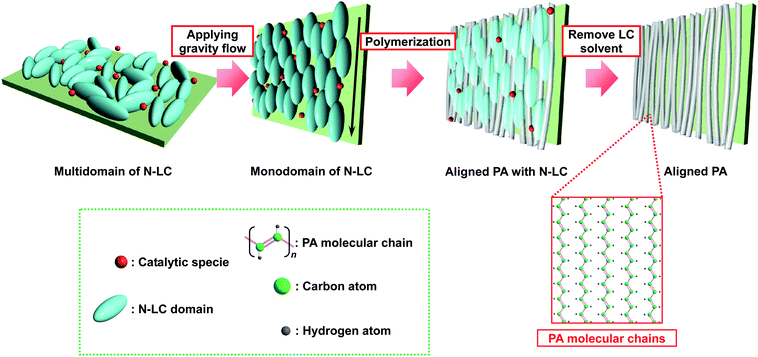 | ||
| Fig. 1 Schematic representation of the synthesis of an aligned PA film using the gravity flow of N-LC solvent. | ||
3. Experimental
The PA thin film was synthesized from acetylene gas of six-nine grade using either toluene or an N-LC as a solvent for the Ziegler–Natta catalyst of triethylaluminium, AlEt3, and tetra-n-butoxytitanium, Ti(O-n-Bu)4. Toluene7,8 and the N-LC13 were used for synthesizing the usual PA film and the aligned PA film, respectively. The concentration of Ti was 400 mmol l−1, those of toluene and the N-LC were both 50 mmol l−1, and the mole ratio of the co-catalyst to the catalyst, [Al]/[Ti], was 4. The N-LC used here was an equimolar mixture of two kinds of phenylcyclohexyl (PCH) derivatives, para-(trans-4-n-propylcyclohexyl)ethoxybenzene (PCH302) and para-(trans-4-n-propylcyclohexyl)butoxybenzene (PCH304). The N-LC showed the nematic phase in the temperature ranges from 18 to 34 °C and −13 to 33 °C in the heating and cooling processes, respectively. The N-LC containing the catalyst was aligned through a gravity flow at 13 °C to make a macroscopically aligned reaction field on the glass wall of a Schlenk flask.Fig. 2 shows the gravity-flow method used for generating an aligned PA film. The N-LC with the catalyst was added to a Schlenk flask using a syringe, and was then coated onto the inner wall of the Schlenk flask by slowly rotating the flask. When the Schlenk flask was placed upright, the N-LC mixture started to flow due to the fluid characteristics of the nematic phase. During the flowing of the N-LC mixture, acetylene gas was immediately introduced into the Schlenk flask. Thus, interfacial polymerization of acetylene proceeded onto the anisotropic reaction field consisting of the aligned N-LC used as a solvent.
 | ||
| Fig. 2 The gravity-flow method used for synthesis of an aligned PA film. | ||
The initial pressure of the acetylene gas was 450 Torr. As-synthesized PA films were washed in turn with purified toluene, a methanol solution containing 1 N hydrochloric acid, and tetrahydrofuran at room temperature under argon gas and then dried in vacuum. The aligned PA film was less than 5 μm in thickness, while the usual PA film synthesized in toluene was about 25 μm in thickness. It should be noted that the PA film synthesized in a macroscopically oriented N-LC using the gravity-flow method has a macroscopically aligned morphology. However, the film thickness at the bottom region becomes thicker than the rest of the regions (the center and top regions). This is due to the difference in thickness of the catalyst solution including N-LC between the bottom and the other regions. For instance, the film thickness at the bottom and the other regions were 2.0 ± 0.1 and 1.5 ± 0.1 μm, respectively. Nevertheless, the present PA film gave long and single nanofibers by virtue of its entanglement-free and aligned fibril morphology.
The ultrasonication was applied to a small piece of the PA film immersed in ethanol at room temperature for several hours in order to separate the bundle of fibers into single fibrils.14 After the ultrasonication, the ethanol solution containing the single fibrils was dripped on a specimen holder for an electron microscope. A scanning electron microscope (SEM, DS-130, Topcon Co.) and a transmission electron microscope (TEM, HF-3000S, Hitachi Co.) were used to investigate the morphological and structural properties of the single fibril. Selected area electron diffraction (SAED) pattern was used to identify crystalline phases of the single nanofibril. The diffraction pattern was measured using a selected-area aperture with a diameter of 100 nm. In the usual PA film, the above-mentioned thickness (25 μm) was too large to be examined with the TEM. Therefore, the acetylene polymerization was performed onto TEM grids.
4. Results and discussion
First, it is appropriate to show the features, morphology, and structure of the usual PA film that was synthesized in toluene for comparison with the aligned PA film. Fig. 3a shows a photograph of the usual PA film with a metallic luster. Fig. 3b depicts an X-ray diffraction (XRD) pattern of the usual PA film, as well as the magnified pattern shown in the inset. The XRD pattern shows sharp (110) and (200) reflections at 0.385 nm (23.1° in 2θ), a small (210) reflection at 0.29 nm (30.8° in 2θ), and a (002) reflection at 0.221 nm (40.8° in 2θ). This indicates that the usual PA film has a highly crystalline region inside the fibril.15,16Fig. 3c and 3d show SEM and TEM images, respectively, of the usual PA thin film showing entangled fibril morphologies. A number of fibrils are aggregated and/or entangled like non-woven fabrics.17,18 The fibrils are 10 to 70 nm in thickness, and each fibril is very short in length (Fig. 3d). The individual fibrils are firmly linked with each other, forming a network. It is easy to imagine that a PA film containing such entangled fibril morphology might be difficult to separate into single fibers.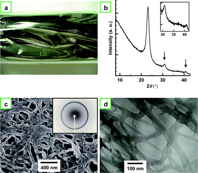 | ||
| Fig. 3 (a) Photograph of a usual PA film with a metallic luster. (b) XRD pattern of the usual PA film. The inset shows the magnified XRD pattern. The pattern shows sharp (110) and (200) reflections at 0.385 nm (23.1° in 2θ), a (210) reflection at 0.29 nm (30.8° in 2θ), and a (002) reflection at 0.221 nm (40.8° in 2θ). (c) SEM and (d) TEM images of the usual PA thin film showing entangled fibril morphology. The inset of (c) shows the XRD pattern of the film. | ||
Fig. 4a depicts the molecular structures of PCH302 and PCH304 and a schematic drawing of N-LC consisting of an equimolar mixture of them. Fig. 4b indicates that the Schlieren texture of N-LC remained unchanged even after an addition of the Ziegler–Natta catalyst of Ti(O-n-Bu)4 and AlEt3. The N-LC containing the catalyst exhibits an aligned optical texture where the direction of the alignment is parallel to that of the gravity of flow, as seen in Fig. 4c.
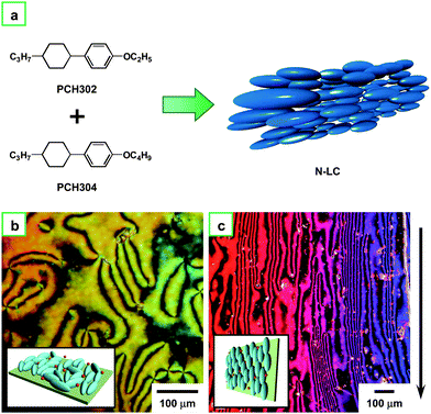 | ||
| Fig. 4 (a) N-LC system composed of an equimolar mixture of PCH302 and PCH304. (b) POM photograph of the N-LC system including the catalyst Ti(O-n-Bu)4 and AlEt3 at 13 °C in the cooling process. (c) POM photograph of the aligned N-LC system containing the catalyst at 13 °C in the cooling process. The arrow indicates the direction of the gravity flow. Insets of (b) and (c) show schematic representations of the N-LC and aligned N-LC, respectively. | ||
Fig. 5a shows a photograph of the aligned PA film synthesized in an N-LC using the gravity-flow technique. The aligned PA film exhibits a dull metallic luster. It shows a linearly polarized dichroism when the polarizer is arranged parallel (bright) or perpendicular (dark) to the aligned direction of the PA film (see Fig. 5b). Fig. 5c shows a SEM image of the aligned PA film, where the fibrils are mutually assembled to form the bundles and the bundles are aligned parallel to the direction of the gravity flow.13,19Fig. 5d depicts an XRD pattern of the aligned PA film, as well as the magnified pattern in the inset. The pattern shows sharp (110) and (200) reflections at 0.373 nm (23.9° in 2θ), a (210) reflection at 0.283 nm (31.6° in 2θ), and a (002) reflection at 0.217 nm (41.7° in 2θ). As seen in Fig. 5e, the fiber diagram in the XRD pattern demonstrates the uniaxial alignment of the PA chains, which is in stark contrast to the Debye-Scherrer ring observed in the usual PA film (see the inset of Fig. 3c). It is worth noting that the aligned PA film showed anisotropy in electrical conductivity. Fig. 5f shows changes of parallel (σ//) and perpendicular (σ⊥) conductivities during vapor phase iodine doping, giving an anisotropic ratio (defined as σ///σ⊥) of 14. The unexpectedly small anisotropy is attributed to closely neighboring bundles of fibrils and diagonally extending fibrils, which enhance the perpendicular conductivity through interfibril hopping of charged carriers and diagonal transportation passes, respectively.
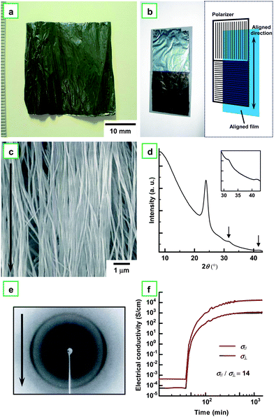 | ||
| Fig. 5 (a) Photograph of aligned PA film with dull metallic luster synthesized in N-LC using the gravity flow technique. (b) Photograph of the aligned PA film, where two polarizers are arranged parallel (bright) and perpendicular (dark) to the aligned direction of the PA film. The schematic illustration is also given in (b). (c) SEM image of the aligned PA film. The arrow indicates the direction of the gravity flow. (d) XRD pattern of the aligned PA film. The inset shows the magnified XRD pattern. The pattern shows sharp (110) and (200) reflections at 0.373 nm (23.9° in 2θ), a (210) reflection at 0.283 nm (31.6° in 2θ), and a (002) reflection at 0.217 nm (41.7° in 2θ). (e) XRD pattern of the aligned PA film. The arrow indicates the direction of the gravity flow. (f) Electrical conductivities of the aligned PA film during the vapor phase iodine doping: σ//, parallel; σ⊥, perpendicular. | ||
Fig. 6a shows a photograph of PA fibrils dispersed in ethanol after ultrasonication for 5 h. Almost all of the dispersed fibrils are aggregated and precipitated at the bottom of the vial after several hours; a very small amount of the fibrils are still floating in the ethanol solution, giving a turbid supernatant (Fig. 6b). The turbid supernatant was pipetted off and dripped onto a specimen holder for SEM measurement. Fig. 6c and 6d show SEM images of the dispersed fibrils and the single fibril, respectively. It is worthwhile to note the change of the aligned PA film during ultrasonication. The PA film is immersed in ethanol and then ultrasonicated. After a couple of hours, the ethanol solution becomes turbid due to the destruction of the film followed by the dispersion of fibrils. At this stage, both the bundled and the dispersed PA fibrils coexist in ethanol solution. The fibril bundles become more separated and finally isolated into single fibrils with an increased ultrasonication time, as shown in Fig. 6a. Actually, the PA film was completely isolated into single fibrils after ultrasonication for 5 h. The single fibril thus prepared is more than 20 μm in length.
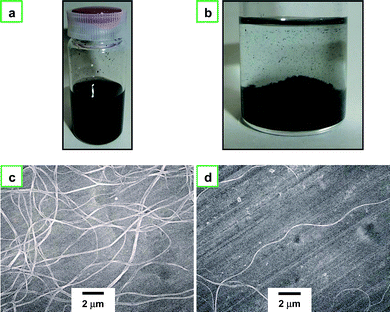 | ||
| Fig. 6 (a) Photograph of PA fibrils dispersed in ethanol after the ultrasonication, and (b) photograph of PA fibrils precipitated at the bottom of the vial after several hours. (c) SEM image of dispersed nanofibrils, (d) SEM image of a single nanofibril with ca. 20 μm in length. | ||
Fig. 7a and 7b show TEM images of the nanofibrils with a uniform thickness of about 60 nm. Fig. 7c and 7d show the TEM image of a single nanofibril, with an arrow indicating the direction of the fibril axis. The inset of Fig. 7c shows the selected area electron diffraction (SAED) pattern. The arrow on the SAED pattern indicates the strong equatorial reflection corresponding to the (110) and (200) faces of cis-PA crystal structure. The SAED pattern exhibits aligned crystal diffraction arcs.20 The photograph of the XRD pattern shown in Fig. 5e is a digital type. The reflections corresponding to the (110) and (200) faces are twin black arcs, which are perpendicular to the fiber axis. On the other hand, the photograph of the SAED pattern shown in the inset of Fig. 7c is an analog type. The reflections corresponding to the (110) and (200) faces are small white arcs, as indicated by two dotted circles in the figure, and they are perpendicular to the fiber axis. Therefore, the diffraction patterns of the XRD and SAED agree with each other in terms of fiber orientation.
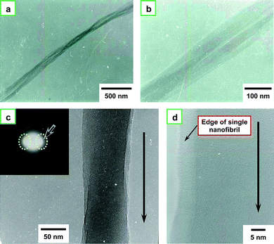 | ||
| Fig. 7 (a) TEM image of nanofibrils and (b) a magnified image of (a). (c) TEM image of single nanofibril and its selected area electron diffraction (SAED) pattern (inset). The arrow in the figure indicates the direction of the fibril axis, and the two dotted circles in the SAED pattern indicate the strong equatorial reflection corresponding to the (110) and (200) faces of the cis-PA crystal structure, and (d) the magnified image of (c). | ||
Note that a “belt” is observed between the fibril and the background in the TEM image of Fig. 7d. This is due to a difference in thickness between the central part and the edge of the fibril. The brightness of a TEM image depends on the thickness of the specimen. Here, the edge of the PA fibril (left side in Fig. 7d) is thinner than the central part of the fibril (right side in Fig. 7d).
Table 1 summarizes reflection distances observed from the two equatorial and two meridional reflections in the negative photograph of the SAED pattern. The indexation of these reflections was carried out on the basis of the crystal structure of cis-PA proposed by Chien.7 It was confirmed that the direction of PA chains was parallel to that of the fibril axis. There are two types of isomers in PA, cis and trans forms, which have different crystal structures.7 The cis form is synthesized using a homogeneous Ziegler–Natta catalyst at very low temperature.8 The trans form is thermally stable, and the thermal isomerization of the cis form to the trans form is complete at about 145 °C.21 It is known that the trans content depends on polymerization temperature and increases continuously with increasing temperature in the thermal treatment of the cis-PA.22 Therefore, both cis and trans crystalline domains coexist in PA films synthesized at room temperature.23 This is the reason why even the aligned PA shows complicated crystalline diffraction pattern due to the two isomers. It was found that the cis content of the aligned PA fibrils was 50–60%. When both the cis and trans crystalline domains coexist in the PA fiber, whatever the content ratio of the two isomers, it can be assumed that no change occurs in terms of the direction of PA chains.23,24 Therefore, although the detailed crystalline structure needs further investigation, it is evident that the PA chains are aligned along the fibril axis.
| Observed reflection distance/nm | Direction | Index (hkl) |
|---|---|---|
| 0.380 | equatorial | (110) (200) |
| 0.227 | equatorial | (020) (120) (310) |
| 0.220 | meridional | (002) |
| 0.119 | meridional | (004) |
5. Conclusion
Aligned PA films were synthesized in a macroscopically oriented N-LC using the gravity-flow method. An entanglement-free bundle of fibrils in an aligned PA film was easily separated into single fibrils having a homogeneous thickness below 100 nm via ultrasonication with an ethanol solvent but without surfactant. The SAED pattern and TEM measurements of the aligned PA film indicated that the PA chains were aligned parallel to the fibril axis of the nanofiber, where both cis and trans crystalline domains coexist. Nanofibers based on PA fibrils should be useful for highly conducting nanowires in plastic electronics.Acknowledgements
This work was supported by a Grant-in-Aid for Science Research (S) (No. 20225007) and that in a Priority Area “Super-Hierarchical Structures” (No. 446) from the Ministry of Education, Culture, Sports, Science and Technology, Japan (MEXT). Part of the work was also supported by the “Nanotechnology Network Project” of the MEXT.References
- F. K. Ko, Nanofiber Technology, in Nanomaterials Handbook, ed. Y. Gogotsi, CRC Press, London, 2006, pp. 553–564 Search PubMed.
- C. R. Martin, Acc. Chem. Res., 1995, 28, 61–68 CrossRef CAS.
- A. G. MacDiarmid, Rev. Mod. Phys., 2001, 73, 701–712 CrossRef CAS.
- J. Joo, K. T. Park, B. H. Kim, M. S. Kim, S. Y. Lee, C. K. Jeong, J. K. Lee, D. H. Park, W. K. Yi, S. H. Lee and K. S. Ryu, Synth. Met., 2003, 135–136, 7–9 CrossRef CAS.
- D. H. Reneker and I. Chun, Nanotechnology, 1996, 7, 216–223 CrossRef CAS.
- A. J. Heeger, Rev. Mod. Phys., 2001, 73, 681–700 CrossRef CAS.
- J. C. W. Chien, Polyacetylene: Chemistry, Physics, and Materials Science, Academic Press, London, 1984 Search PubMed.
- (a) H. Shirakawa, Synthesis of Polyacetylene, in Handbook of Conducting Polymers, ed. T. A. Skotheim, R. L. Elsenbaumer and J. R. Reynolds, Marcel Dekker Inc., New York, 2nd edn, 1998, pp. 197–208 Search PubMed; (b) H. Shirakawa, Rev. Mod. Phys., 2001, 73, 713–718 CrossRef CAS.
- (a) K. Akagi, G. Piao, S. Kaneko, K. Sakamaki, H. Shirakawa and M. Kyotani, Science, 1998, 282, 1683–1686 CrossRef CAS; (b) K. Akagi, S. Guo, T. Mori, M. Goh, G. Piao and M. Kyotani, J. Am. Chem. Soc., 2005, 127, 14647–14654 CrossRef CAS; (c) M. Goh, T. Matsushita, M. Kyotani and K. Akagi, Macromolecules, 2007, 40, 4762–4771 CrossRef CAS; (d) T. Mori, M. Kyotani and K. Akagi, Macromolecules, 2008, 41, 607–613 CrossRef CAS; (e) K. Akagi and T. Mori, Chem. Rec., 2008, 8, 395–406 CrossRef CAS; (f) K. Akagi, Chem. Rev., 2009, 109, 5354–5401 CrossRef CAS.
- (a) M. Goh, M. Kyotani and K. Akagi, J. Am. Chem. Soc., 2007, 129, 8519–8527 CrossRef CAS; (b) T. Mori, T. Sato, M. Kyotani and K. Akagi, Macromolecules, 2009, 42, 1817–1823 CrossRef CAS.
- Y. Zhou, M. Freitag, J. Hone, C. Staii, A. T. Johnson, Jr., N. J. Pinto and A. G. MacDiarmid, Appl. Phys. Lett., 2003, 83, 3800–3802 CrossRef CAS.
- (a) J. G. Park, G. T. Kim, V. Krstic, B. Kim, S. H. Lee, S. Roth, M. Burghard and Y. W. Park, Synth. Met., 2001, 119, 53–56 CrossRef CAS; (b) A. N. Aleshin, H. J. Lee, Y. W. Park and K. Akagi, Phys. Rev. Lett., 2004, 93, 196601–196601-4 CrossRef CAS; (c) H. J. Lee, Z. X. Jin, A. N. Aleshin, J. Y. Lee, M. J. Goh, K. Akagi, Y. S. Kim, D. W. Kim and Y. W. Park, J. Am. Chem. Soc., 2004, 126, 16722–16723 CrossRef CAS.
- (a) K. Araya, A. Mukoh, T. Narahara and H. Shirakawa, Chem. Lett., 1984, 1141–1142 CAS; (b) K. Araya, A. Mukoh, T. Narahara and H. Shirakawa, Synth. Met., 1986, 14, 199–206 CrossRef CAS; (c) K. Akagi, H. Shirakawa, K. Araya, A. Mukoh and T. Narahara, Polym. J., 1987, 19, 185–189 CrossRef CAS; (d) K. Araya, A. Mukoh, T. Narahara, K. Akagi and H. Shirakawa, Synth. Met., 1987, 17, 247–252 CrossRef CAS.
- (a) M. Kyotani, H. Goto, K. Suda, T. Nagai, Y. Matsui and K. Akagi, J. Nanosci. Nanotechnol., 2008, 8, 1999–2004 CrossRef CAS; (b) M. Kyotani, S. Matsushita, T. Nagai, Y. Matsui, M. Shimomura, A. Kaito and K. Akagi, J. Am. Chem. Soc., 2008, 130, 10880–10881 CrossRef CAS; (c) S. Matsushita, M. Kyotani and K. Akagi, Synth. Met., 2009, 159, 2198–2201 CrossRef CAS.
- T. Akaishi, K. Miyasaka, K. Ishikawa, H. Shirakawa and S. Ikeda, J. Polym. Sci., Polym. Phys. Ed., 1980, 18, 745–750 CrossRef CAS.
- A. Montaner, M. Rolland, J. L. Sauvajol, M. Galtier, R. Almairac and J. L. Ribet, Polymer, 1988, 29, 1101–1104 CrossRef CAS.
- G. E. Wnek, J. C. W. Chien, F. E. Karasz, M. A. Druy, Y. W. Park, A. G. MacDiarmid and A. J. Heeger, J. Polym. Sci., Polym. Lett. Ed., 1979, 17, 779–786 CrossRef CAS.
- A. J. Epstein, H. Rommelmann, R. Fernquist, H. W. Gibson, M. A. Druy and T. Woerner, Polymer, 1982, 23, 1211–1221 CrossRef CAS.
- M. Kyotani, S. Matsushita, T. Nagai, Y. Matsui and K. Akagi, Synth. Met., 2007, 157, 546–550 CrossRef CAS.
- A. Montaner, M. Rolland, J. L. Sauvajol, L. Meynadier, R. Almairac, J. L. Ribet, M. Galtier and C. Gril, Synth. Met., 1989, 28, D19–D25 CrossRef CAS.
- T. Ito, H. Shirakawa and S. Ikeda, J. Polym. Sci., Polym. Chem. Ed., 1975, 13, 1943–1950 CrossRef CAS.
- T. Ito, H. Shirakawa and S. Ikeda, J. Polym. Sci., Polym. Chem. Ed., 1974, 12, 11–20 CrossRef CAS.
- L. C. Dickinson, J. A. Hirsch, F. E. Karasz and J. C. W. Chien, Macromolecules, 1985, 18, 2374–2379 CrossRef CAS.
- Y. Tanabe, H. Kyotani, K. Akagi and H. Shirakawa, Macromolecules, 1995, 28, 4173–4178 CrossRef CAS.
| This journal is © The Royal Society of Chemistry 2010 |