Controlled ionic condensation at the surface of a native extremophile membrane†
Sonia Antoranz
Contera‡
*,
Kislon
Voïtchovsky§‡
* and
John F.
Ryan
University of Oxford, Bionanotechnology IRC, Clarendon Laboratory, Physics Department, Parks Road, OX1 3PU, Oxford, UK. E-mail: s.antoranzcontera1@physics.ox.ac.uk; kvoitcho@mit.edu
First published on 4th December 2009
Abstract
At the nanoscale level biological membranes present a complex interface with the solvent. The functional dynamics and relative flexibility of membrane components together with the presence of specific ionic effects can combine to create exciting new phenomena that challenge traditional theories such as the Derjaguin–Landau–Verwey–Overbeek (DLVO) theory or models interpreting the role of ions in terms of their ability to structure water (structure making/breaking). Here we investigate ionic effects at the surface of a highly charged extremophile membrane composed of a proton pump (bacteriorhodopsin) and archaeal lipids naturally assembled into a 2D crystal. Using amplitude-modulation atomic force microscopy (AM-AFM) in solution, we obtained sub-molecular resolution images of ion-induced surface restructuring of the membrane. We demonstrate the presence of a stiff cationic layer condensed at its extracellular surface. This layer cannot be explained by traditional continuum theories. Dynamic force spectroscopy experiments suggest that it is produced by electrostatic correlation mediated by a Manning-type condensation of ions. In contrast, the cytoplasmic surface is dominated by short-range repulsive hydration forces. These findings are relevant to archaeal bioenergetics and halophilic adaptation. Importantly, they present experimental evidence of a natural system that locally controls its interactions with the surrounding medium and challenges our current understanding of biological interfaces.
1. Introduction
Biological membranes present many levels of complexity. Although their primary role is to physically separate the cell from the outside medium, they are active participants in many cellular processes. They play essential roles in signalling, adhesion, sensing, cell–cell interactions, regulating molecular trafficking, sensing, viral and bacterial infection and are involved in cell bioenergetics. Biological membranes have evolved highly optimized mechanisms and structures to successfully carry out all these tasks. The diversity of biomolecules composing the membrane, their particular physical and chemical properties (charge, flexibility, ability to interact specifically) and their particular organization, all contribute to making biological membranes an extraordinary system with interfacial properties largely unmatched by most inorganic or engineered surfaces. Ions are one of the key components in the natural medium of most living cells. They interact often strongly and specifically with the membrane, they can affect its physical properties (see ref. 1 and references therein), cohesion2,3 and are necessary for biological function.4–6 At the nanoscale, electrostatic effects between different ions and charged biomolecules in aqueous solution produce some perplexing effects. Hofmeister noted in 1888 that some salts help to precipitate proteins from solution (salting-out) while other salts enhance their solubility (salting-in).7 These effects are traditionally explained by the influence of saltions on the structure of water, these interpretations have introduced a persistent oversimplification: the concept of “structure making” (kosmotrope) and “structure-breaking” (chaotrope) ions (Hofmesiter series). In this framework, large, low-charge ions disrupt water structure while small highly charged ions are structure-makers inducing order on the hydrogen-bonded water network. Salting-in and salting-out are then explained by entropic changes in the hydration shells of proteins. The existence of Hofmeister series seems to suggest an underlying simplicity, however specific ion effects continue to defy all-encompassing theories.8 New compelling evidence suggests that ions do not, in general, simply disperse homogeneously throughout the solution creating a “mean-field” solvent; rather ions tend to segregate preferentially at either hydrophilic or hydrophobic surfaces.9,10 Not surprisingly, the biological interface is the most complex to understand. To the best of our knowledge, no valid theoretical framework able to treat these local interactions is available at the present time. The most widely used approach is the so-called Deryaguin–Landau–Verwey–Overbeek (DLVO) model, which fails to explain much of the available experimental data. DLVO theory separates electrostatic forces from attractive quantum mechanical electrodynamic fluctuation forces (van der Waals or dispersion forces).11 Importantly, DLVO theory does not take into account ionic size and specificity,12–14 yet cells (and membranes) can select e.g. potassium over sodium.12,15 Short-range hydration forces and the discrete effects of charges, ions and water molecules are not taken into account in DLVO theory either. Finally, we note that electrostatic interactions of highly charged biomacromolecules can be dominated by correlations in their counterion environment16,17 which cannot be taken into account with DLVO theory.Here we study ionic effects and quantify short-range (sub-nm) interactions naturally occurring at the interface between an extremophile membrane and its acqueous environement. These so-called purple membranes (PM) occupy up to 50% of the surface area of Halobacterium salinarium a micro-organism living in hypersaline lakes. PM contain only one type of protein (bacteriorhodopsin, bR) assembled together with highly charged lipids (1![[thin space (1/6-em)]](https://www.rsc.org/images/entities/char_2009.gif) :10) into a two-dimensional hexagonal lattice of bR trimers. bR functions as a light-driven proton pump and is a prototype for vectorial transport across the cell membrane.18 It is composed of seven trans-membrane α-helices which enclose a retinalchromophore. An enormous amount of biochemical, genetic and spectroscopic investigations have been dedicated to understanding the vectorial proton-pumping mechanism of bR,19–25 and although there are different conflicting data sets and interpretations26–28 a coherent picture of a ∼10 ms photocycle process has emerged: Photo-isomerization of the retinal produces a steric and electrostatic mismatch that is relaxed through local conformational changes within bR. These changes become larger throughout the photocycle and spread gradually to the membrane surface. They are accompanied by proton transfers and side-change rearrangements that facilitate the movement of the proton from the cytoplasmic surface to the extracellular surface through the hydrophobic protein core. Water-filled cavities inside bR are fundamental in this process.29–32 Many important questions remain unanswered, in particular neither the proton release nor the proton uptake is understood33 and a plausible explanation of the functional role of the crystalline arrangement of bR trimers has not yet been found. These surface processes are controlled by very complex solvent-mediated local interactions in which the role of ions is expected to be fundamental, especially since bR adaptation to its extreme and highly asymmetric native environment (extracellularNaCl > 3 M, cytoplasmic KCl > 3 M) has produced specificity of surface interactions between proteins, lipids and ions.34 PM is therefore an ideal system to investigate both global and specific ionic effects at a biomembrane interface, especially given its highly charged surfaces with asymmetric dynamics;2 and specific ion-binding sites at its extracellular surface.35
:10) into a two-dimensional hexagonal lattice of bR trimers. bR functions as a light-driven proton pump and is a prototype for vectorial transport across the cell membrane.18 It is composed of seven trans-membrane α-helices which enclose a retinalchromophore. An enormous amount of biochemical, genetic and spectroscopic investigations have been dedicated to understanding the vectorial proton-pumping mechanism of bR,19–25 and although there are different conflicting data sets and interpretations26–28 a coherent picture of a ∼10 ms photocycle process has emerged: Photo-isomerization of the retinal produces a steric and electrostatic mismatch that is relaxed through local conformational changes within bR. These changes become larger throughout the photocycle and spread gradually to the membrane surface. They are accompanied by proton transfers and side-change rearrangements that facilitate the movement of the proton from the cytoplasmic surface to the extracellular surface through the hydrophobic protein core. Water-filled cavities inside bR are fundamental in this process.29–32 Many important questions remain unanswered, in particular neither the proton release nor the proton uptake is understood33 and a plausible explanation of the functional role of the crystalline arrangement of bR trimers has not yet been found. These surface processes are controlled by very complex solvent-mediated local interactions in which the role of ions is expected to be fundamental, especially since bR adaptation to its extreme and highly asymmetric native environment (extracellularNaCl > 3 M, cytoplasmic KCl > 3 M) has produced specificity of surface interactions between proteins, lipids and ions.34 PM is therefore an ideal system to investigate both global and specific ionic effects at a biomembrane interface, especially given its highly charged surfaces with asymmetric dynamics;2 and specific ion-binding sites at its extracellular surface.35
Here we use the unique capability of amplitude-modulation atomic force microscopy (AM-AFM) operated at small amplitudes (<2 nm) to achive sub-nm resolution maps of the interaction forces between the AFM tip and PM. We characterize and quantify the local (down to single α-helix level) and global interactions that make possible the proton uptake, release at the interface of bR with the solvent and study their deviation from DLVO theory. We exploit rapidly decaying, short-range forces36 at the surface of bR so as to confine the image formation interaction to the front-most atoms of the tip and enhance the resolution. We demonstrate the presence of a stiff cationic layer condensed at the PM extracellular surface. This layer cannot be explained by traditional continuum theories and its properties depend on the ionic species involved. Dynamic force spectroscopy experiments suggest that it is produced by electrostatic correlation mediated by a Manning-type condensation of ions.
In contrast, we propose that the cytoplasmic surface is dominated by short-range repulsive hydration forces.11,37
2. Materials and methods
2.1 Sample preparation
Dried Purple membrane (PM) from Halobacterium salinarium (Sigma-Aldrich Co. St. Louis, M., USA) were rehydrated by stirring in 10 mM Tris-HCl solution at pH 8 at 50 °C for 1 h. PM was then dissolved in the desired experimental buffer (∼15 μg mL−1) and deposited (30 μL) onto freshly cleaved mica (9.9 mm mica discs, Agar Scientific, Essex, UK) for 5 min. The samples were then gently rinsed with imaging buffer (2 mL). For adsorption with buffer containing only monovalent ions with concentration <50 mM, PM adsorption was carried out by putting a drop (50 μL) of PM in solution (50 mM KCl, 10 mM Tris-HCl) on freshly cleaved mica to prevent ill-formation or no adsorption of the membrane. The samples were subsequently rinsed with the desired experimental buffer. In all cases imaging was performed after adding some more buffer (∼200 μL). All the experimental buffers contained the specified salt composition (KCl, NaCl, MgCl2) and 10 mM Tris at pH 8. Buffers were prepared with ultrapure water (18.2 MΩ, Milipore, Billerica, MA, USA) and the chemicals necessary for the preparation were purchased from Sigma-Aldrich (Dorset, UK).2.2 Imaging and acquisition of extension curves
All images were recorded with a commercial MFP-3D AFM (Asylum Research, Santa Barbara, CA) with closed-loop feedback in the x-, y-, and z-directions. Imaging was carried out with Olympus silicon nitride microcantilevers (nominal spring constant kn = 0.57 N m−1 (TR800), kn = 0.39 N m−1 and kn = 0.78 N m−1 (RC800), Olympus, Tokyo, Japan). The spring constant of the each cantilever was calibrated using the thermal noise method.38,39 Thermal noise scans always indicated a similar value for a given type of cantilever (within <10%), suggesting a good reproducibility of the cantilever stiffness. High resolution was achieved in various saline solutions at pH 8, close to the isoelectric point of silicon nitride.40 Before imaging, the system was left for 2–3 h scanning a blank sample to reach equilibrium. For each image, height, amplitude, and phase information were acquired simultaneously. The scan speed was typically 4–9 lines/s for high-resolution frames. The PM lattice was used for lateral calibration of the scanner and quantification of the drift. Acquired images were corrected for drift and low-pass filtered to remove high-frequency noise, but no averaging was done. High-resolution images (Fig. 1) were low-pass filtered with progressive reduction (down to 50% of the intensity i.e. squared amplitudes) of frequencies higher than typically 2–2.5 nm−1. In the case of Fig. 1H, a lower frequency limit of 1.5 nm−1 was selected. The resolution achieved was generally sufficient to allow unambiguous differentiation of both sides of the membrane.2,41 The side attribution could also be confirmed using the phase image (see Fig. 3).2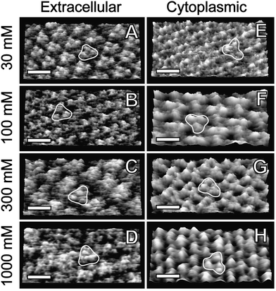 | ||
| Fig. 1 Topography AM-AFM images of purple membrane at different KCl concentrations. The left panels (A–D) show the membraneextracellular surface and the right panels (E–H) the cytoplasmic surface, identified by high-resolution and phase imaging (see Fig. 3). A single trimer is highlighted in all the images. The scale bars are 6 nm. Conditions that maximize resolution: extracellular side at (A) 30 mM KCl, A0 = 9 Å, A = 5.3 Å, k = 0.39 N m−1; (B) 100 mM, A0 = 10 Å, A = 6.7 Å, k = 0.57 N m−1; (C) 300 mM, A0 = 11 Å, A = 4.7 Å, k = 0.57 N m−1; (D) 1M, A0 = 9.5 Å, A = 4.8 Å, k = 0.8 N m−1. Cytoplasmic side at (E) 30 mM, A0 = 8.4 Å, A = 5 Å, k = 0.39 N m−1; (F) 100 mM, A0 = 10 Å, A = 8 Å, k = 0.57 N m−1; (G) 300 mM, A0 = 11.6 Å, A = 5.5 Å, k = 0.57 N m−1 (H) 1 M, A0 = 1.1 nm, A = 4.7 Å, k = 0.8 N m−1. All images are displayed in 3D with a z-range of 5 Å. RMS roughness is (A) 1.5 Å, (B) 1.4 Å, (C) 1.5 Å, (D) 1.2 Å, (E) 1.2 Å, (F) 2.4 Å, (G) 2.4 Å, (H) 1.4 Å. | ||
Extension curves (amplitude and phase vs. distance curves) were acquired on both the extracellular and the cytoplasmic PM surface in each buffer condition studied. Typically 50–100 measurements were averaged for each curve presented here. Extension and retraction velocity was 200 nm s−1. Immediately after each set of measurements, high-resolution images were obtained to verify that no permanent damage had been made to the membrane. For comparison, extension curves where also taken on mica before and after curves acquisition on PM. In this way we could calculate the inverse optical lever sensitivity (nm V−1) and ensure stability of the system throughout our measurements.
To avoid systematic errors, each set of measurements carried out in a specific buffer condition was made in a random order.
3. Results
3.1 Sub-molecular resolution imaging of purple membrane
In order to determine the dominant interactions at the surface of PM we first investigate the effects of ionic concentration on both cytoplasmic and extracellular surfaces using high-resolution AM-AFM imaging.Fig. 1A–D show the effect of [KCl] on the extracellular surface. The resolution could be maximized by carefully selecting the amplitude of the oscillation A (see Fig. 1 caption) and choosing a cantilever stiffness k close to that of the PM sample investigated.2 At low salt concentration (30 mM) three distinct monomeric protrusions are distinguishable within the trimer. As the salt concentration increases, the trimers become more compact and for 300 mM and 1 M KCl only single trimeric protrusions are visible (Fig. 1C–D). Salt concentration does not affect the extent to which bR protrudes from the membrane (∼1.2 Å); its extracellular surface remains bound to the lipids through specific interactions that are not electrostatic.2,42 In contrast, monomers and trimers at the cytoplasmic surface are almost indiscernible at low salt concentration; bR inter-helical loops are visible (Fig. 1D) protruding ∼1 Å from the lipid matrix. As the salt concentration increases, distinct trimers appear more detached (Fig. 1F–H). At 300 mM KCl individual α-helices become visible and protrude ∼2 Å from the membrane; this suggests stabilization and hydration of individual helices at higher K+ concentration. This tendency is confirmed at 1 M KCl where the proteins protrude 2.3 Å from the lipid in the cytoplasmic side.
3.2 Quantification of local interactions: small-amplitude dynamic force spectroscopy
In order to quantify tip–sample interactions at the membrane surface, we simultaneously recorded amplitude and phase vs. distance curves at 30 mM, 100 mM, 300 mM and 1 M KCl respectively, on both sides of the membrane and on mica for comparison (see Fig. S1 of the ESI† ). When A is sufficiently small, the surface interaction potential probed by the AFM tip can be approximated as locally parabolic,43 and the tip–sample force Fts becomes: Fts ≈ Fts0 − ktsz, where z is the tip–sample distance and kts is the local tip–sample force gradient called “tip–sample interaction stiffness”. The cantilever-tip system is then described by the harmonic oscillator model with a linear damping factor that accounts for the viscoelasticity of the medium. Near resonance and at small amplitudes, kts can be expressed as a function of the free oscillation amplitude A0, the phase shift relative to the driving signal φ, and A, namely: kts = kA0![[hair space]](https://www.rsc.org/images/entities/char_200a.gif) cosφ/A, where k is the cantilever stiffness.43 It should be noted that due to the low quality factor of the cantilever oscillation in liquid (typically 2–5), the use of the harmonic oscillator model becomes contentious when the tip oscillates very close to the sample (<1 nm). Practically, direct tip–sample coupling leads to the loss of a well defined resonance (over-damping) and unambiguous interpretation of the data becomes difficult. This can be observed in the phase vs. distance curves (Fig. S1† ) which, after reaching a minimum as the tip approaches the membrane, start to re-increase. To avoid this problem, we therefore used this phase minimum as an indication of the limit of applicability of the harmonic oscillator model and disregarded the region of the curves corresponding to tip–sample distances closer than this phase minimum. ktsvs. z curves were calculated using the relations deduced above, as presented in Fig. 2A–D (the insets present the same data in semi-logarithmic plots). As the tip approaches the sample, kts increases up to a maximum approximately corresponding to the phase minimum. kts curves should therfore not be considered beyond this maximum. In each case, A0 was identical as for the high-resolution images presented in Fig. 1. In order to allow direct comparison of the curves, the origin (z = 0) was determined as the tip–sample distance where the cantilever's average deflection starts increasing linearly as the z-piezo extends.
cosφ/A, where k is the cantilever stiffness.43 It should be noted that due to the low quality factor of the cantilever oscillation in liquid (typically 2–5), the use of the harmonic oscillator model becomes contentious when the tip oscillates very close to the sample (<1 nm). Practically, direct tip–sample coupling leads to the loss of a well defined resonance (over-damping) and unambiguous interpretation of the data becomes difficult. This can be observed in the phase vs. distance curves (Fig. S1† ) which, after reaching a minimum as the tip approaches the membrane, start to re-increase. To avoid this problem, we therefore used this phase minimum as an indication of the limit of applicability of the harmonic oscillator model and disregarded the region of the curves corresponding to tip–sample distances closer than this phase minimum. ktsvs. z curves were calculated using the relations deduced above, as presented in Fig. 2A–D (the insets present the same data in semi-logarithmic plots). As the tip approaches the sample, kts increases up to a maximum approximately corresponding to the phase minimum. kts curves should therfore not be considered beyond this maximum. In each case, A0 was identical as for the high-resolution images presented in Fig. 1. In order to allow direct comparison of the curves, the origin (z = 0) was determined as the tip–sample distance where the cantilever's average deflection starts increasing linearly as the z-piezo extends.
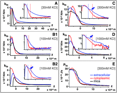 | ||
| Fig. 2 Tip–sample force gradient kts plotted vs. distance z at (A) 30 mM, k = 0.39 N m−1, (B1, B2) 100 mM, k = 0.57 N m−1, k = 0.39 N m−1 (C) 300 mM. k = 0.57 N m−1 and (D) 1 M KClk = 0.8 N m−1 for extracellular (red) and cytoplasmic (blue) sides compared with mica (black); the force fields correspond to Fig. 1 imaging conditions. Insets (a–d) show the curves on semi-logarithmic plots. At 100 mM KCl, only the softer cantilever k = 0.39 N m−1 (B2) can detect a shoulder in kts induced by the extracellular ionic layer. When present, the extracellular shoulder is indicated by an arrow. The vertical dashed line separates different region of the curves (short-range/long-range, see text). A typical Ptsvs. z curve (300 mM KCl) is presented in (E). | ||
At 30 mM KCl, kts reflects the asymmetry of the membrane: the extracellular leaflet is less charged than the cytoplasmic leaflet and exhibits longer range interactions. Both leaflets show a strictly monotonic repulsive interaction, which validate the assumption of a locally parabolic potential. The bare mica surface, on the other hand, shows an additional attractive region. This instability induces an oscillation in the imaging AFM feedback which becomes noise in mica images (Fig. 3A)
At 100 mM KCl, Fig. 2B1, the kts measured with the cantilever employed for high-resolution imaging (0.57 N m−1) still exhibits a longer range interaction for the extracellular surface than the cytoplasmic surface. However, when using a softer cantilever (0.39 N m−1), a distinctive shoulder appears on the extracellular surface (arrow in Fig. 2B2). This shoulder is 2 ± 0.5 nm thick and marks a transition between two different exponential regimes of kts (inset).
At 300 mM KCl (Fig. 2C), the kts curve measured on the extracellular leaflets also exhibit a shoulder (arrow), qualitatively similar to that 100 mM (Fig. 2B2) but with a stiffer kts. The cytoplasmic kts curves exhibit a similar although stiffer behavior than at lower salt concentrations.
At 1 M KCl (Fig. 2D), extracellular and cytoplasmic leaflets curves are qualitatively similar to 100 and 300 mM curves, but with an even stiffer kts.
At small amplitudes, it is also useful to calculate the average tip energy dissipation Pts (J s−1):
 | (1) |
 | ||
| Fig. 3 (A) Topographic images of a purple membrane patch at 30 mM KCl. The non-linearity in the force field over the mica produces a “noisy” image of the mica surface while the membrane cytoplasmic side appears free of noise, due to the monotonic repulsive force field. (B) Topographic image of extracellular (left) and cytoplasmic (right) membrane sides; no obvious contrast visible. (C) Phase image corresponding to (B) showing a contrast between the extracellular side (darker, left) and the cytoplasmic (lighter, right) reflecting differences in energy dissipation during scanning. The scale bars are 300 nm (A) and 40 nm (B) and (C). | ||
3.3 Effects of cation charge and size in extracellular ionic condensation
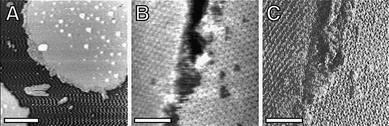
To study the effect of cation charge and size and to probe the membraneextracellular surface at conditions closer to those of the living organism, ktsvs.z curves were obtained in solutions containing salts in proportions equivalent to those of the extracellular growth medium (1 M NaCl, 10 mM KCl, 20 mM MgCl2, 10 mM Tris-HCl, pH 8), Fig. 4(A–D).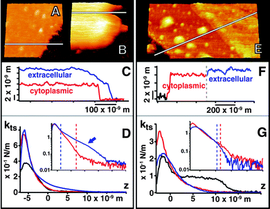 | ||
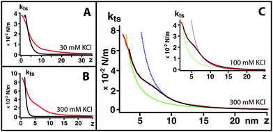
| Fig. 4 Images of the cytoplasmic (A) and extracellular side of PM (B) at 1 M NaCl, 10 mM KCl, 20 mM MgCl2 showing the 6 nm counterion layer at the extracellular surface in the cross section (C). (D) shows the ktsvs. z and corresponding logarithmic plot corresponding to these conditions. (E) shows the cytoplasmic and extracellular side at 50 mM MgCl2 and the ∼1.5 nm counterion layer at the extracellular surface in (F) and corresponding ktsvs. z curves (G). For (D) and (G), the corresponding amplitude and phase vs. z curves are presented in Fig. S2 of the ESI† . | ||
Under these conditions, an ionic layer even thicker (6 ± 0.5 nm) than that observed in KCl is formed at the extracellular surface but high-resolution images are still possible after breaking through this layer (not shown). The measured kts is however softer than in KCl at the same concentration. These results show differences produced by the counterion size. Theories predict that the condensation should be stronger with divalent counterions, therefore we performed experiments in MgCl2. The presence of the condensed layer at the extracellular surface is also demonstrated in 50 mM MgCl2 solution (10 mM Tris-HCl, pH 8) as shown in Fig. 4E–G. The layer is thinner in this case (1.5 ± 0.2 nm), but so stiff that the cantilever cannot break it during force curves experiments, even using the highest possible k cantilever that would not break the membrane.
4. Discussion
4.1 Side-specific ionic effects: cytoplasmic interface
The ktsvs.z curves acquired over the membrane's cytoplasmic surface tend to exhibit short-range interaction decaying exponentially over 3–5 nm, as it can be seen in the semi-log plot inset in Fig. 2A–D (left part of the red dotted lines in the insets) at all the ionic concentrations investigated. The weak dependence on the ionic concentration (non-DLVO behaviour) and the short-range exponential decay can be interpreted as due to solvent-mediated repulsive hydration forces. These forces can have different origins such as anomalous dielectric response of water at the interface, hydration of ions or osmotic effects of hydrated ions trapped between two approaching surfaces.11,45,46 At larger distances from the membrane surface (right part of the red doted lines in the insets of Fig. 2A–D), the exponential behaviour vanishes and kts reaches zero. The transition from the exponential regime is however dependent on the ionic concentration, suggesting weak longer-range electrostatic effects. As the ionic concentration increases these effects are better screened; only the short-range forces interpreted as ion-mediated hydration forces remain, thus leading to a more abrupt transition from the exponential regime to zero (inset Fig. 2D).4.2 Side-specific ionic effects: extracellular interface ionic condensation
The ktsvs. z curves acquired on the on the extracellular surface (Fig. 2A–D) also present an exponentially decaying repulsive interaction at short range (typically below ∼1 nm, left of the blue dotted line in the insets A–D). It is followed by a distinct shoulder ∼2 nm wide and stiffening (increased kts) with increasing salt concentrations (arrow in Fig. 2B–D); then kts exponentially decays at longer distance from the surface. The fact that the salt concentration influences the stiffness of the shoulder but hardly its size strongly suggests that it originates from lateral correlation of an ion–water layer forming on the surface. Indeed, this layer could be directly observed in the AFM images (Fig. 1C–D), and was reinforced in ionic conditions close to native of the membrane (Fig. 4B and E). The high negative surface charge of PM, the existence of specific extracellular ionic binding sites and the crystalline arrangement of bR trimers all support the possibility of electrostatic correlations of condensed counterions forming a structured layer at the extracellular membrane surface. The shoulder in the extracellular curves is then interpreted as arising from the transition from long-range PB-type interactions to short-range correlation interactions. A highly-ordered quasi-2D layer of correlated counterions (akin to a Wigner glass) has been predicted to occur in highly charged biomacromolecules with multivalent cations.16AFM force spectroscopy has been previously used to study electrostatic correlations between surfaces in a saline solution.47 Here, using AC force spectroscopy at low amplitudes, we provide an experimental way to quantify the lateral correlation of the ion layer adjacent to the extracellularmembrane: the energy Pts dissipated in the ion layer. A typical power dissipation vs. distance (Ptsvs.z) curve is presented in Fig. 2E for 300 mM KCl. Increasing the ionic concentration increases Pts, but does not change significantly the overall shape of the Ptsvs.z curves apart from reducing the z-range of the measured dissipation, as for kts curves. The salt-enhanced stiffness of the extracellular condensed cation layer (i.e. the lateral counterion correlation, as detected by kts) is reflected by an increase of Pts (Fig. 2E) over the extracellular surface. This is consistent with the loss of imaging resolution observed for the extracellular side of the membrane at higher salt concentration [Fig. 1(B–D)]. It is interesting to note that experiments carried out in similar conditions (300 mM KCl) but without dynamically oscillating the cantilever, i.e. contact-mode, did not detect this cationic layer.2,48 However, when imaging PM using a cantilever oscillated at higher frequencies49 than in the present work, extracellular patches appeared substantially thicker than cytoplasmic patches (7.2 nm and 5.7 nm respectively)49 suggesting that the cationic layer has a viscoelastic behaviour.4.3 Comparison with theories: electrostatic correlation of ions
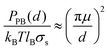
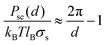
Unsurprisingly, cytoplasmic and extracellular curves cannot be explained with DLVO theory. Fitting the curves to the DLVO and extended-DLVO models (adding exponential repulsive hydration) provided poor fits and unphysical results (Fig. 4A–B). Fitting the cytoplasmic kts curves with DLVO theory provided better results than for the extracellularkts, but the evolution of the curves with the salt concentration does not follow DLVO predictions.Charge correlation is well known in condensed matter, especially in electron systems at low temperature where a rich variety of classical and quantum liquid and solid states are observed. Correlated ion behaviour occurs in macromolecular systems, and charge localization or “crystallization” is predicted to occur when correlation is sufficiently strong.16 Electrostatic correlations are known to be important in biological systems, e.g. in DNA condensation,50,51 the binding of F-actin polymers in the presence of counterions,52 and charge transport across biological membranes.53 Theoretical studies have been proposed to explain electrostatic correlations at surfaces in the presence of counterions,16,17,54 however no analytical solutions are available for systems where additional ions are present in solution. Furthermore, very little experimental evidence has been obtained at the relevant short length scales necessary to probe these interactions and to test the available theoretical predictions. To verify whether correlation effects could, at least qualitatively, describe our observations, we fitted the kts curves acquired on the PM extracellular surface with a combination of two functions (Fig. 5C): a traditional Poisson–Bolztman (PB) description at distances d much larger than the Gouy–Chapman length μ, and the strong correlation theory (Strong Coupling (SC) theory 55) at shorter distances from the interface. To fit the mean-field PB region of the kts curves we use the derivative of the analytical expression for the pressure between two walls separated by d obtained from the contact value theorem, PPB:
 | ||
| Fig. 5 (A) Experimental extracellularktsvs.z curve (red) at 30 mM KCl compared with the DLVO prediction (black). (B) The same at 300 mM KCl. (C) shows a fit of the experimental ktsvs.z curve (red) at 100 and 300 mM KCl fitted with a combination of SC and PB. SC component in green and PB in blue. | ||
The SC theory admits an analytical solution for strongly correlated systems where the counterions form a 2D crystal. with this solution:
This is valid in the limit where the coupling parameter Ξ → ∞ (Ξ = 2πq3lBσs),
The transition between the PB and SC regimes is then done with a sigmoid function (transition length Δ) and the function used for the fitting is
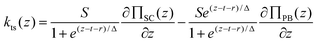 | (2) |
Qualitatively our force curves present a good agreement with the theory, although the model is an over simplification of the experimental conditions, mostly due to the direct application of the SC theory in an ionic environment.
Using eqn (2), it is possible to fit kts reasonably well (Fig. 5C) and from the fit we find that:
• At 30 mM KCl, σs = 0.14 e nm−2, Ξ = 0.44.
• At 100 mM KCl, σs = 0.22 e nm−2, Ξ = 0.69.
• At 300 mM KCl, σs = 0.24 e nm−2, Ξ = 0.76.
• At 1000 mM KCl, σs = 0.47 e nm−2, Ξ = 1.45.
The values of surface charge are reasonable and consistent with previous reports of two or three specific ion binding sites associated with the extracellular surface of purple membrane.35,56 However the Ξ values are much lower than expected for the intermediate coupling regime predicted by the SC theory. The main source of error in this analysis comes from the large number of fitting parameters and the non-linear nature of the model which result in large standard deviations (20–100%). We find counterion condensation for both monovalent and divalent cations, but theories predict this to occur with mainly multivalent counterions. Importantly, counterion condensation theories do not take into account the dynamic nature of biological function; as demonstrated here the cytoplasmic side, despite being globally more negatively charged, avoids the formation of a correlated ionic layer using an enhanced flexibility and intercalation of positive charge at the surface to produce a dynamic electric field that avoids specific ion binding. Our experiments demonstrate the need of more sophisticated theories to describe ionic condensation at biological interfaces.
4.4 Proposed biological relevance
Based on these observations, a general description of the forces at the surface of bR can be proposed. The bR cytoplasmic surface is highly negatively charged and undergoes large conformational changes during the bR photocycle.18,19 The resulting highly fluctuating electric field prevents ionic condensation and promotes α-helix hydration. On the other hand, the extracellular side is static, stiff, features specific bR-lipids interactions and is rather flat. Its static character facilitates the formation of a stable and spatially defined force field, inducing binding of cations to specific locations i.e. Manning-like condensation. We propose that this is an important function of the crystalline arrangement of purple membrane, an evolved mechanism to produce correlated electrostatics. The finding of this correlated ionic layer modifies the current picture of the role of electrostatics in the bioenergetics of haloarchea. Although there is strong experimental and theoretical evidence that supports surface transfer of protons from sources (e.g. bR) to proton sinks (e.g.ATP-synthases) the mechanism of such transfer remains unknown.57,58 Our new findings suggest an intriguing new possibility: the interaction of the released proton with a correlated ionic layer at the extracellular surface would provide a fast and surface-based transfer mechanism (Fig. 6). Furthermore, the condensed cation layer dielectric barrier extends over ∼2 nm, enhancing the build-up of surface capacitance and the formation of a large transmembrane electrochemical proton gradient between the surfaces (protonmotive force). The existence of a correlated ionic layer may provide an additional effect by increasing stiffness of the extracellular surface at higher salt concentrations.2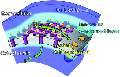 | ||
| Fig. 6 Suggested role of the extracellular condensed ionic layer in the membrane bio-energetics. The presence of a correlated ionic layer could enhance proton surface transfer to proton sinks in the membrane. Furthermore the condensed ionic layer constitutes a dielectric barrier for the proton to leave the membrane. | ||
The absence of a counterion condensation at the cytoplasmic surface can explain the ultra-fast proton uptake. At low and high salt concentrations the membrane response on both sides is qualitatively the same revealing the physical strategies of halophiles to adapt to a large range of environmental conditions.
5. Conclusions
We have used small-amplitude AM-AFM to image and quantify the local forces at the surfaces of an extremophile membrane. Our results reveal the presence of a specific and well controlled force field, exhibiting a large asymmetry between both sides of the membrane. The extracellular surface controls the presence of a layer of condensed ions which behaviour appears best described by ion correlation effects. In contrast the cytoplasmic surface is highly dominated by dynamic short-range hydration forces that can prevent ion condensation. These findings, related to the membrane local properties, are important to understand the force fields that trap and release protons at a biological membrane interface. Furthermore, the presence of a condensed ionic layer at the extracellular surface could be involved in proton transfer at the surface of the membrane.Acknowledgements
Financial support from BBSRC, EPSRC, MRC and MoD through the Bionanotechnology IRC is acknowledged. KV acknowledges funding from a Lord Florey fellowship.References
- A. Aroti, E. Leontidis, M. Dubois and T. Zemb, Biophys. J., 2007, 93, 1580–1590 CrossRef CAS.
- K. Voitchovsky, S. Antoranz Contera, M. Kamihira, A. Watts and J. F. Ryan, Biophys. J., 2006, 90, 2075–2085 CrossRef CAS.
- J. N. Sachs and T. B. Woolf, J. Am. Chem. Soc., 2003, 125, 8742–8743 CrossRef CAS.
- S. Genet, R. Costalat and J. Burger, Biophys. J., 2001, 81, 2442–2457 CrossRef CAS.
- K. J. Swartz, Nature, 2008, 456, 891–897 CrossRef CAS.
- J. Åqvist and V. Luzhkov, Nature, 2000, 404, 881–884 CrossRef CAS.
- F. Hofmeister, Naunyn-Schmiedebergs Arch. Pharmacol., 1888, 24, 247–260.
- D. J. Tobias and J. C. Hemminger, Science, 2008, 319, 1197–1198 CrossRef CAS.
- Y. Levin, Phys. Rev. Lett., 2009, 102, 147803–147804 CrossRef.
- P. Ball, Chem. Rev., 2008, 108, 74–108 CrossRef CAS.
- J. N. Israelachvili, Academic Press, London, 2nd Ed., 1992.
- W. Kunz, P. Lo Nostro and B. W. Ninham, Curr. Opin. Colloid Interface Sci., 2004, 9, 1–18 CrossRef CAS.
- S. Woelki and H. H. Kohler, Chem. Phys., 2004, 306, 209–217 CrossRef CAS.
- M. G. Cacace, E. M. Landau and J. J. Ramsden, Q. Rev. Biophys., 1997, 30, 241–277 CrossRef CAS.
- H. I. Petrache, T. Zemb, L. Belloni and V. A. Parsegian, Proc. Natl. Acad. Sci. U. S. A., 2006, 103, 7982–7987 CrossRef CAS.
- A. Y. Grosberg, T. T. Nguyen and B. I. Shklovskii, Rev. Mod. Phys., 2002, 74, 329–345 CrossRef CAS.
- I. Rouzina and V. A. Bloomfield, J. Phys. Chem., 1996, 100, 9977–9989 CrossRef CAS.
- J. K. Lanyi, Nature, 1995, 375, 461–463 CrossRef CAS.
- S. Subramaniam and R. Henderson, Nature, 2000, 406, 653–657 CrossRef CAS.
- H. J. Sass, G. Buldt, R. Gessenich, D. Hehn, D. Neff, R. Schlesinger, J. Berendzen and P. Ormos, Nature, 2000, 406, 649–653 CrossRef CAS.
- A. Royant, K. Edman, T. Ursby, E. Pebay-Peyroula, E. M. Landau and R. Neutze, Nature, 2000, 406, 645–648 CrossRef CAS.
- E. Pebay-Peyroula, G. Rummel, J. P. Rosenbusch and E. M. Landau, Science, 1997, 277, 1676–1681 CrossRef CAS.
- H. Luecke, B. Schobert, H. T. Richter, J. P. Cartailler and J. K. Lanyi, Science, 1999, 286, 255–260 CrossRef CAS.
- H. Luecke, H. T. Richter and J. K. Lanyi, Science, 1998, 280, 1934–1937 CrossRef CAS.
- J. Herbst, K. Heyne and R. Diller, Science, 2002, 297, 822–825 CrossRef CAS.
- J. K. Lanyi and B. Schobert, Biochemistry, 2004, 43, 3–8 CrossRef CAS.
- H. Kamikubo and M. Kataoka, Biophys. J., 2005, 88, 1925–1931 CrossRef CAS.
- R. Neutze, E. Pebay-Peyroula, K. Edman, A. Royant, J. Navarro and E. M. Landau, Biochim. Biophys. Acta, Biomembr., 2002, 1565, 144–167 CrossRef CAS.
- H. Luecke, Biochim. Biophys. Acta, Bioenerg., 2000, 1460, 133–156 CrossRef CAS.
- F. Garczarek, L. S. Brown, J. K. Lanyi and K. Gerwert, Proc. Natl. Acad. Sci. U. S. A., 2005, 102, 3633–3638 CrossRef CAS.
- N. A. Dencher, H. J. Sass and G. Buldt, Biochim. Biophys. Acta, Bioenerg., 2000, 1460, 192–203 CrossRef CAS.
- F. Garczarek and K. Gerwert, Nature, 2006, 439, 109–112 CrossRef CAS.
- J. K. Lanyi, Biochim. Biophys. Acta, Bioenerg., 2000, 1460, 1–3 CrossRef CAS.
- A. Oren, Microbiol. Mol. Biol. Rev., 1999, 63, 334–348 CAS.
- S. Tuzi, J. Hasegawa, R. Kawaminami, A. Naito and H. Saito, Biophys. J., 2001, 81, 425–434 CrossRef CAS.
- F. J. Giessibl, Rev. Mod. Phys., 2003, 75, 949–983 CrossRef CAS.
- D. Leckband and J. Israelachvili, Q. Rev. Biophys., 2001, 34, 105–267 CrossRef CAS.
- J. L. Hutter and J. Bechhoefer, Rev. Sci. Instrum., 1993, 64, 1868–1873 CrossRef CAS.
- H. J. Butt and M. Jaschke, Nanotechnology, 1995, 6, 1–7 CrossRef.
- J. Biscan, N. Kallay and T. Smolic, Colloids Surf., A, 2000, 165, 115–123 CrossRef CAS.
- D. J. Müller, J. B. Heymann, F. Oesterhelt, C. Möller, H. Gaub, G. Buldt and A. Engel, Biochim. Biophys. Acta, Bioenerg., 2000, 1460, 27–38 CrossRef CAS.
- R. Henderson, J. S. Jubb and S. Whytock, J. Mol. Biol., 1978, 123, 259–274 CrossRef CAS.
- P. M. Hoffmann, S. Jeffery, J. B. Pethica, H. O. Özer and A. Oral, Phys. Rev. Lett., 2001, 87, 265502 CrossRef CAS.
- B. Anczykowski, B. Gotsmann, H. Fuchs, J. P. Cleveland and V. B. Elings, Appl. Surf. Sci., 1999, 140, 376–382 CrossRef CAS.
- J. Faraudo and F. Bresme, Phys. Rev. Lett., 2005, 94, 077802 CrossRef.
- S. Marcelja, Nature, 1997, 385, 689–690 CrossRef CAS.
- O. Zohar, I. Leizerson and U. Sivan, Phys. Rev. Lett., 2006, 96, 177802 CrossRef.
- D. J. Müller, D. Fotiadis, S. Scheuring, S. A. Müller and A. Engel, Biophys. J., 1999, 76, 1101–1111 CrossRef CAS.
- M. Dong, S. Husale and O. Sahin, Nat. Nanotechnol., 2009, 4, 514–517 CrossRef CAS.
- L. C. Gosule and J. A. Schellman, Nature, 1976, 259, 333–335 CAS.
- Z. Reich, E. J. Wachtel and A. Minsky, Science, 1994, 264, 1460–1463 CrossRef CAS.
- T. E. Angelini, R. Golestanian, R. H. Coridan, J. C. Butler, A. Beraud, M. Krisch, H. Sinn, K. S. Schweizer and G. C. L. Wong, Proc. Natl. Acad. Sci. U. S. A., 2006, 103, 7962–7967 CrossRef CAS.
- S. Bernèche and B. Roux, Nature, 2001, 414, 73–77 CrossRef CAS.
- A. Naji, S. Jungblut, A. G. Moreira and R. R. Netz, Phys. A, 2005, 352, 131–170 CrossRef.
- A. G. Moreira and R. R. Netz, Phys. Rev. Lett., 2001, 87, 078301 CrossRef CAS.
- C. D. Heyes, K. B. Reynolds and M. A. El-Sayed, FEBS Lett., 2004, 562, 207–210 CrossRef CAS.
- J. Heberle, J. Riesle, G. Thiedemann, D. Oesterhelt and N. A. Dencher, Nature, 1994, 370, 379–382 CrossRef CAS.
- A. Y. Mulkidjanian, Biochim. Biophys. Acta, Bioenerg., 2006, 1757, 415–427 CrossRef CAS.
Footnotes |
| † Electronic supplementary information (ESI) available: Figs. S1 and S2: amplitude- and phase-extension curves used to derive the data presented in Figs. 2 and 4. See DOI: 10.1039/b9nr00248k |
| ‡ These authors contributed equally to this work. |
| § Present address: Massachusetts Institute of Technology, DMSE, Bldg 13-4069, 77 Massachusetts Avenue, Cambridge MA 02139, USA |
| This journal is © The Royal Society of Chemistry 2010 |