Low-power microfluidic electro-hydraulic pump (EHP)
Clarissa
Lui
*a,
Scott
Stelick
a,
Nathaniel
Cady
c and
Carl
Batt
b
aCornell University, 318 Stocking Hall, Ithaca, NY 14850, USA. E-mail: csl42@cornell.edu; Fax: +1 607-255-8741; Tel: +607-255-7902
bCornell University, 318 Stocking Hall, Ithaca, NY 14850, USA. E-mail: cab10@cornell.edu; Fax: +1 607-255-8741; Tel: +607-255-2896
cCollege of Nanoscale Science & Engineering, University at Albany, 257 Fuller Road, Albany, NY 12203, USA. E-mail: ncady@uamail.albany.edu; Tel: +1 518-956-7354
First published on 30th October 2009
Abstract
Low-power electrolysis-based microfluidic pumps utilizing the principle of hydraulics, integrated with microfluidic channels in polydimethylsiloxane (PDMS) substrates, are presented. The electro-hydraulic pumps (EHPs), consisting of electrolytic, hydraulic and fluidic chambers, were investigated using two types of electrodes: stainless steel for larger volumes and annealed gold electrodes for smaller-scale devices. Using a hydraulic fluid chamber and a thin flexible PDMS membrane, this novel prototype successfully separates the reagent fluid from the electrolytic fluid, which is particularly important for biological and chemical applications. The hydraulic advantage of the EHP device arises from the precise control of flow rate by changing the electrolytic pressure generated, independent of the volume of the reagent chamber, mimicking the function of a hydraulic press. Since the reservoirs are pre-filled with reagents and sealed prior to testing, external fluid coupling is minimized. The stainless steel electrode EHPs were manufactured with varying chamber volume ratios (1![[thin space (1/6-em)]](https://www.rsc.org/images/entities/char_2009.gif) :
:![[thin space (1/6-em)]](https://www.rsc.org/images/entities/char_2009.gif) 1 to 1
1 to 1![[thin space (1/6-em)]](https://www.rsc.org/images/entities/char_2009.gif) :
:![[thin space (1/6-em)]](https://www.rsc.org/images/entities/char_2009.gif) 3) as a proof-of-concept, and exhibited flow rates of 1.25 to 30 µl/min with electrolysis-based actuation at 2.5 to 10 VDC. The miniaturized gold electrode EHPs were manufactured with 3 mm diameters and 1
3) as a proof-of-concept, and exhibited flow rates of 1.25 to 30 µl/min with electrolysis-based actuation at 2.5 to 10 VDC. The miniaturized gold electrode EHPs were manufactured with 3 mm diameters and 1![[thin space (1/6-em)]](https://www.rsc.org/images/entities/char_2009.gif) :
:![[thin space (1/6-em)]](https://www.rsc.org/images/entities/char_2009.gif) 1 chamber volume ratios, and produced flow rates of 1.24 to 7.00 µl/min at 2.5 to 10 VAC, with a higher maximum sustained pressure of 343 KPa, suggesting greater device robustness using methods compatible with microfabrication. The proposed technology is low-cost, low-power and disposable, with a high level of reproducibility, allowing for ease of fabrication and integration into existing microfluidic lab-on-a-chip and analysis systems.
1 chamber volume ratios, and produced flow rates of 1.24 to 7.00 µl/min at 2.5 to 10 VAC, with a higher maximum sustained pressure of 343 KPa, suggesting greater device robustness using methods compatible with microfabrication. The proposed technology is low-cost, low-power and disposable, with a high level of reproducibility, allowing for ease of fabrication and integration into existing microfluidic lab-on-a-chip and analysis systems.
Introduction
Precise low-power control of fluid flow at the microscale is crucial for the successful development of lab-on-a-chip and portable polymerase chain reaction (PCR) systems.1 In the past decade, extensive research in microfluidic device technology2–4 has paved new paths for micro total analysis systems (µTAS) and other multi-functional detection platforms5–9 with applications in genomic sequencing,10–13 drug discovery,14–17 single-cell analysis,18–23 and diagnostics.1,24–26 Since traditional syringe pumps have a low potential for integration,27 considerable interest has been shown in developing small-scale microfluidic pumps to replace the macro-scale mechanical pumps.28–32Microfluidic pumps currently employ a variety of different actuation mechanisms: thermopneumatics,33,34 electrostatics,35–37 piezoelectrics,38–40 electromagnetics,41–43 and hydrogels,44,45 among others. Some microfluidic pumps focus on controlled delivery of micro- and nanolitre solutions over long periods of time, while others seek to achieve high pumping volumes at low power. Thermal and electrolytically-generated bubbles have been investigated for their utility in miniaturized pumps, microfluidic dosing experiments,46 and are favorable due to simple fabrication and ease of control. The disadvantage of thermal production of H2O vapor bubbles is the risk of denaturation of biological molecules due to overheating.47 In addition, the electrolytic production of bubbles has been shown to be far more energy efficient than thermal bubble generation.3
In this article, we illustrate an electrolysis-based pressure actuation for a low-power microfluidic pump.48–53 The novelty of this device lies in using the existing electrolytic pressure drive technology in conjunction with a hydraulic chamber, in order to actuate the reagent chamber for precise control of flow rate. The new pump design efficiently isolates the actuation mechanism from the reagent chamber in order to prevent contamination between the different fluids, which is of particular importance for biological and chemical applications.47 In addition, the pump flow rate is independent of the size of the reagent chamber, allowing for variable amount of reagents to be pumped for a given electrolytic actuation power. Operation of the EHP would not require external fluid coupling, since the reservoirs would be pre-filled with sample and sealed prior to operation. The pump demonstrates ease of fabrication and operation, low power consumption, and customizability of these pumps offer great potential for effortless integration into existing microfluidic systems.
Theory of operation
The basic microfluidic EHP design consists of two pumping chambers that separate contain pumping fluid (electrolyte) and liquid reagents. Electrodes are placed in the electrolyte chamber (EC) and gas bubbles are produced via electrolysis when a voltage is applied. The increased pressure within the EC chamber due to the generation of gas bubbles is transferred to the fluid in the hydraulic chamber (HC) via a thin flexible membrane (Fig. 1). The HC is split into two effective chambers, one that responds to the EC and the other actuates the reagent chamber (RC). The pressure applied to the hydraulic fluid from the EC is translated to the RC, forcing the reagent to be pumped through an outlet. In this way, small amounts of electrical energy can be used to pump fluids in a controlled manner. Unlike previous pump designs,48–53 this design effectively uses an indirect electrolysis-powered hydraulic mechanism to separate the reagent fluid from the electrolyte.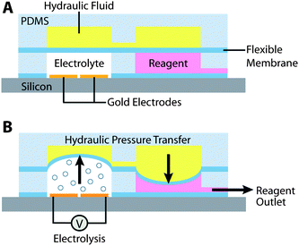 | ||
| Fig. 1 The Electro-hydraulic Pump. Overall schematic of the electro-hydraulic pump shows the mechanism of activation. Pumping fluid (electrolyte) is subjected to an electrical current, causing bubble formation through electrolysis. Pressure is transferred through a flexible membrane to a hydraulic fluid chamber, which then forces fluid out of the reagent reservoir. | ||
Pascal's law of fluid dynamics states that a change in pressure applied to an enclosed fluid is transmitted undiminished to every point of the fluid and the walls of the containing vessel, and has been demonstrated in applications such as the hydraulic press. The microfluidic EHP system incorporates this hydraulic press principle into the pump design. When a force F1 is applied to the EC of area A1, a resulting pressure P is transmitted to the RC of area A2 as a force of F2. The pressure is constant in both chambers independent of the areas A1 and A2, as illustrated in Equation (1).
 | (1) |
The hydraulic advantage of this pump design dictates that the volume of reagent fluid pumped is independent of the size of the RC. Thus, the device fabrication can be tailored for specific applications by varying the size of RC, while the power for electrolytic actuation remains constant for a fixed flow rate. The flow rate of the pumps can be precisely controlled by the amount of voltage applied to the electrolytic chamber. Since actuation of the pump does not require larger external devices, the pumps as well as the associated electronics can be scaled down dramatically allowing for integration into lab-on-a-chip systems. This innovative design can also provide higher output pressures than traditional pumps, and the size of the reagent chambers can be modified to provide a hydraulic advantage.
Materials & methods
Microfabrication process
EHP fluidic structures are constructed by casting polydimethylsiloxane (Sylgard 184, Dow Corning, Midland, MI) onto an SU-8 photoresist mold (Microchem, Newton, MA). For proof-of-concept using larger-scale stainless steel EHPs, the SU-8 molds are modified with hemispherical lenses to control chamber volumes. PDMS pre-polymer is mixed with a curing agent at a 10![[thin space (1/6-em)]](https://www.rsc.org/images/entities/char_2009.gif) :
:![[thin space (1/6-em)]](https://www.rsc.org/images/entities/char_2009.gif) 1 mass ratio and degassed in a vacuum chamber before pouring into the SU-8 mold. To fabricate the flexible membrane, PDMS is spun onto a thin plastic transparency at a spin speed of 1000 rpm for 30s to achieve a membrane thickness of 60 µm. The individual PDMS components are baked at 60 °C for 60 minutes until hardened. The EHP is assembled as illustrated in Fig. 1, with the top hydraulic fluid chambers and the bottom electrolyte and reagent chambers separate by a thin flexible PDMS membrane.
1 mass ratio and degassed in a vacuum chamber before pouring into the SU-8 mold. To fabricate the flexible membrane, PDMS is spun onto a thin plastic transparency at a spin speed of 1000 rpm for 30s to achieve a membrane thickness of 60 µm. The individual PDMS components are baked at 60 °C for 60 minutes until hardened. The EHP is assembled as illustrated in Fig. 1, with the top hydraulic fluid chambers and the bottom electrolyte and reagent chambers separate by a thin flexible PDMS membrane.
Stainless steel electrode EHPs
Stainless steel pins (Swan Secure Products, Inc, Baltimore, MD) were secured with epoxy adhesive in the polystyrene base of the electrolyte pump chambers. These electrodes showed no signs of degradation over a five week period and the completed system could withstand 150 KPa of pressure without leaking. To optimize the microfluidic EHP design, we developed a method to fill the EHP chambers and to develop novel microfluidic connections between EHPs and microfluidic components. Microfluidic connectors involving modified SMA fiber optic connectors (Thorlabs, Newton, NJ) were designed. One end of the connector was a SMA fiber optic connector threaded with 0.25 mm 27-gauge stainless steel tubing, while the corresponding end incorporated 0.62 mm Tygon tubing (Small Parts, Miramar, FL). Small gauge PEEK™ 1572 tubing (Upchurch Scientific, Oak Harbor, WA) was then attached with pressure-tight fittings. The SMA mating adapter kept these two pieces of tubing aligned, and when tightened, formed a watertight seal between the two connectors. The connection was reusable and could be used repeatedly without compromising its watertight seal. Fig. 2(a) shows a completed stainless steel electrode EHP prototype and a section of the microfluidic connector.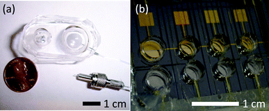 | ||
Fig. 2
Completed prototype EHP pump. (a) 1 mL stainless steel model with a 9![[thin space (1/6-em)]](https://www.rsc.org/images/entities/char_2009.gif) : :![[thin space (1/6-em)]](https://www.rsc.org/images/entities/char_2009.gif) 4 chamber area ratio (EC 4 chamber area ratio (EC![[thin space (1/6-em)]](https://www.rsc.org/images/entities/char_2009.gif) : :![[thin space (1/6-em)]](https://www.rsc.org/images/entities/char_2009.gif) RC), shown with a microfluidic connector (b) Device containing four gold electrode EHP modules with 15 µL reagent reservoirs. RC), shown with a microfluidic connector (b) Device containing four gold electrode EHP modules with 15 µL reagent reservoirs. | ||
Gold electrode EHPs
In order to further miniaturize the system for ease of fabrication and integration with existing microfluidic platforms, 250 nm-thick gold electrodes were e-beam evaporated onto a bare silicon wafer with a 500 nm thermal oxide layer, and annealed at 400 °C for 120 minutes. The annealing step prevents the rapid peeling of gold during electrolysis and helps prolong the life of the device. The PDMS chamber assembly is plasma treated, aligned to the gold electrodes, and bonded to the wafer surface. Small gauge tubing (PEEK™ 1572, Oak Harbor, WA) was inserted into the inlets and outlets, and secured using Silicone Solutions high-strength adhesive sealant SS-67A (Twinsburg, OH), shown in Fig. 2(b). After filling of the chambers and re-sealing, copper wires were attached to the electrode pads using Circuitworks® CW2400 conductive silver epoxy (Chemtronics, Kennesaw, Georgia).Experimental setup & protocol
The microfluidic EHP pumps and control system underwent exhaustive testing to determine flow rates and reliability with different applied pumping parameters. The electrolyte used in the electrolyte chamber was TRIS-acetate, EDTA. The hydraulic chamber was filled with degassed DI water through input and output channels designed into the device. Prior to testing, the filling channels are sealed with silicone sealant. Flow rate analysis was conducted to determine the minimum and maximum rates, as well as the steady state rates of sustained pumping.For the stainless steel EHP devices, calibration curves of flow rate vs. applied voltage were created using a variety of different reagents, including buffers and solvents. Flow rates were determined volumetrically using a high-sensitivity microbalance (Mettler Toledo AX26, Columbus, OH). Variation in the flow rates with respect to the size of the respective electrolyte and reagent chambers was examined. The diameter of the chambers was varied from 6 mm- to 75 mm and the chamber volume ratios varied from 1![[thin space (1/6-em)]](https://www.rsc.org/images/entities/char_2009.gif) :
:![[thin space (1/6-em)]](https://www.rsc.org/images/entities/char_2009.gif) 1 to 1
1 to 1![[thin space (1/6-em)]](https://www.rsc.org/images/entities/char_2009.gif) :
:![[thin space (1/6-em)]](https://www.rsc.org/images/entities/char_2009.gif) 3. In this manner we could systematically examine the effect of reservoir size and hydraulic advantage on the pumping rates and pressure.
3. In this manner we could systematically examine the effect of reservoir size and hydraulic advantage on the pumping rates and pressure.
Due to the smaller volumes and shorter operation times of the gold electrode EHP devices, the flow rates of 3 mm-diameter devices were measured using a high-sensitivity microbalance in conjunction with National Instruments Labview® software to capture the flow rates in real time. The pressure testing was conducted in a similar fashion, by connecting a pressure sensor to the pump outlet and monitoring with Labview®.
Results and discussion
Stainless steel electrodes
Figure 3(a) shows the proportional dependence of fluid flow rate on the applied DC voltage for a pump with 12 mm diameter chambers using PBS, Ethanol and DI water as reagents. The chambers were filled with 0.93 mL of fluid and voltages applied to induce the electrolytic process. The flow rate was measured volumetrically over time. The average maximum flow rate was 16 µL/min for sustained flow powered at 7 VDC (Figure 3(b)). The chambers are hemispherical, creating a dome-shaped chamber. Bubbles formed in the electrolyte chamber uniformly rose to the peak of this dome and the flexible membrane could be stretched to make contact with the entire hydraulic chamber surface. This reduced all of the dead volume in the chambers and resulted in more consistent pumping profiles. During testing, EHP outputs were attached to a pressure sensor during fluid pumping at 10.6 V (approx. 30 µl/min) and maximum pressure was measured upon device failure (fluid leakage). The maximum pressure of 150 KPa was obtained with 20 mm diameter electrolytic chambers and 25 mm reagent chambers (a hydraulic ratio of 1.6![[thin space (1/6-em)]](https://www.rsc.org/images/entities/char_2009.gif) :
:![[thin space (1/6-em)]](https://www.rsc.org/images/entities/char_2009.gif) 1). This pressure exceeds the requirements for pumping through lab-on-a-chip systems.
1). This pressure exceeds the requirements for pumping through lab-on-a-chip systems.
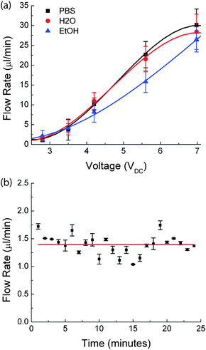 | ||
| Fig. 3 Stainless Steel Electrode EHP Testing. The testing of stainless steel electrode EHPs involved measuring (a) the effect of voltage on the flow rate of various solvents (deionized water, PBS, ethanol); (b) the flow rate of a device powered at 7.0 VDC over an operation time of 25 minutes was monitored to determine long term flow rate variation. The error bars show the variations in flow rate for two experiments. | ||
Since the hydraulic fluid can be assumed to be incompressible, the pressure generated by electrolysis is transferred to the reagent chamber without any loss. Also, the pressure generated is independent of the reagent chamber allowing for flexibility for the pump to be suited for different applications. Figure 4 shows the invariability of the output flow rate at different DC voltages, with increasing EC![[thin space (1/6-em)]](https://www.rsc.org/images/entities/char_2009.gif) :
:![[thin space (1/6-em)]](https://www.rsc.org/images/entities/char_2009.gif) RC area ratios. The volume flow rates for different area ratios at a given DC voltage fall within the error bars on the graph, indicating no significant variation.
RC area ratios. The volume flow rates for different area ratios at a given DC voltage fall within the error bars on the graph, indicating no significant variation.
 | ||
Fig. 4
Conservation of Flow Rate. The effect of chamber area ratio (EC![[thin space (1/6-em)]](https://www.rsc.org/images/entities/char_2009.gif) : :![[thin space (1/6-em)]](https://www.rsc.org/images/entities/char_2009.gif) RC) on pump output flow rate is investigated for DI water at different applied DC voltages. This shows that for different area ratios, the effective flow rate is constant, at a given applied voltage for electrolysis. RC) on pump output flow rate is investigated for DI water at different applied DC voltages. This shows that for different area ratios, the effective flow rate is constant, at a given applied voltage for electrolysis. | ||
A flow rate standard deviation in ±0.5 µL/min was observed over time. Notably, pumping at lower flow rates (1–5 µL/min) resulted in more stable flow rate profiles when compared to higher flow rates, which can be attributed to more uniform bubble production within the electrolyte chamber. This fluctuation is in part due to the irregular bubble formation and lack of feedback control. Long-term testing demonstrated that EHPs could be operated for 30 min per day for up to 5 weeks (using large volume reagent reservoirs). Although these tests showed that pumps continued to be operational for extended periods of time, it was noted that the electrolysis chamber lost pressure between subsequent tests. Therefore, re-pressurization was required during each test, resulting in a short (1–2 min) delay before fluid was expelled from the pump. This further demonstrates the need for a feedback control system to monitor fluid expulsion and resulting flow rate.
Gold electrodes
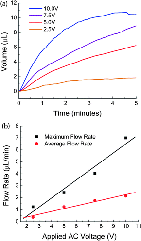 | ||
| Fig. 5 Gold Electrode EHP Flow Rate Testing. The flow rate testing on gold electrode EHPs involved measuring (a) the fluid volume expelled from the device at each applied AC voltage (b) the effect of varying voltage on the flow rate. | ||
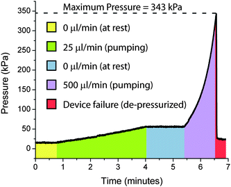 | ||
| Fig. 7 Gold Electrode EHP Pressure Testing. The maximum pressure testing involved pressurizing with an external pump and monitoring using a pressure sensor hooked to the pump outlet, to the point of device failure at 343 kPa. | ||
Apart from the miniaturization advantage and the low power consumption, precise pumping rates with low variability are important for many microfluidic devices and it is clear that opportunities exist to establish a feed back control to regulate the voltage applied to the system. Therefore, future designs will focus on the design and integration of a feedback control system to measure the flow rate and use this information for operational feedback.
Conclusion
In summary, we have demonstrated that EHPs can provide the necessary fluid flow rates and pressures for microfluidic analytical systems. The proposed technology is low-cost and disposable with a high level of reproducibility. The polymer-based fabrication methods are compatible with standard microfabrication technologies, making it possible to directly integrate these pumps with lab-on-a-chip systems. The work resulted in an improved EHP design that could deliver a wide range of flow rates (1.25 µl/min to 30 µl/min) and was compatible with aqueous buffers and organic solvents (water, PBS, and ethanol). We note that improvements could be made to increase longevity of gold electrodes with improved designs and materials, as well as investigations into pulsed device operation. In addition, feedback control could be implemented to improve the flow rate variance in sustained long-term pumping.Pumps were fabricated entirely from polymeric materials (polystyrene and PDMS), suggesting the feasibility of low-cost, high throughput manufacturing. In addition, an electronic module was developed to deliver precise pumping voltages under software control. Fluid flow rates were proportional to the applied voltage, making it possible to roughly predict control pumping parameters. While the stainless steel electrodes were effective, the integration of the gold electrodes represented a challenge in developing a more integrated manufacturing approach to the system. The deposition of the electrodes by processes compatible with standard silicon processing allows us to move forward with a more integrated, scalable manufacturing process. Our approach holds great potential for the miniaturization of pressure-driven microfluidic applications in which fluid must be delivered quickly and efficiently.
Acknowledgements
The authors would like to thank the staff at the Cornell NanoScale Science & Technology Facility (CNF) for the use of the facilities and technical advice. This work was supported by the Department of Justice and the United States Department of Agriculture.Note and references
- N. C. Cady, S. Stelick, M. V. Kunnavakkam and C. A Batt, Sens. Actuators, B, 2005, 107, 332–341 CrossRef.
- D. J. Beebe, G. A. Mensing and G. M. Walker, Annu. Rev. Biomed. Eng., 2002, 4, 261–286 CrossRef CAS.
- T. M. Squires, Rev. Mod. Phys., 2005, 77, 977–1026 CrossRef CAS.
- G. M. Whitesides, Nature, 2006, 442, 368–373 CrossRef CAS.
- D. R. Reyes, D. Iossifidis, P. A. Auroux and A. Manz, Anal. Chem., 2002, 74, 2623–2636 CrossRef CAS.
- P. A. Auroux, D. Iossifidis, D. R. Reyes and A. Manz, Anal. Chem., 2002, 74, 2637–2652 CrossRef CAS.
- D. Erickson and D. Li, Anal. Chim. Acta, 2004, 507, 11–26 CrossRef CAS.
- S. Haeberle and R. Zengerle, Lab Chip, 2007, 7, 1094–1110 RSC.
- P. S. Dittrich, K. Tachikawa and A. Manz, Anal. Chem., 2006, 78, 3887–3908 CrossRef CAS.
- R. G. Blazej, P. Kumaresan and R. A. Mathies, Proc. Natl. Acad. Sci. U. S. A., 2006, 103, 7240–7245 CrossRef CAS.
- C. P. Fredlake, D. G. Hert, E. R. Mardis and A. E. Barron, Electrophoresis, 2006, 27, 3689–3702 CrossRef CAS.
- L. Chen, A. Manz and P. J. R. Day, Anal. Biochem., 2008, 372, 128–130 CrossRef CAS.
- A. H. Dewald, B. L. Poe and J. P. Landers, Expert Opin. Med. Diagn., 2008, 2, 963–977 Search PubMed.
- J. Pihl, M. Karlsson and D. T. Chiu, Drug Discovery Today, 2005, 10, 1377–1383 CrossRef CAS.
- P. S. Dittrich and A. Manz, Nat. Rev. Drug Discovery, 2006, 5, 210–218 CrossRef CAS.
- J. El-Ali, P. K. Sorger and K. F. Jensen, Nature, 2006, 442, 403–411 CrossRef CAS.
- L. Kang, B. G. Chung, R. Langer and A. Khademhosseini, Drug Discovery Today, 2008, 13, 1–13 CrossRef CAS.
- H. Andersson and A. Van den Berg, Curr. Opin. Biotechnol., 2004, 15, 44–49 CrossRef CAS.
- J. Gao, X. F. Yin and Z. L. Fang, Lab Chip, 2004, 4, 47–52 RSC.
- L. M. Borland, S. Kottegoda, K. Scott Phillips and N. L. Allbritton, Annu. Rev. Anal. Chem., 2008, 1, 191–227 Search PubMed.
- D. Cohen, J. A. Dickerson, C. D. Whitmore, E. H. Turner, M. M. Palcic, O. Hindsgaul and N. J. Dovichi, Annu. Rev. Anal. Chem., 2008, 1, 165–190 Search PubMed.
- K. Sato, K. Mawatari and T. Kitamori, Lab Chip, 2008, 8, 1992–1998 RSC.
- N. M. Toriello, E. S. Douglas, N. Thaitrong, S. C. Hsiao, M. B. Francis, C. R. Bertozzi and R. A. Mathies, Proc. Natl. Acad. Sci. U. S. A., 2008, 105, 20173–20178 CrossRef CAS.
- P. Belgrader, W. Benett, D. Hadley, G. Long, R. Mariella, Jr., F. Milanovich, S. Nasarabadi, W. Nelson, J. Richards and P. Stratton, Clinical Chemistry, 1998, 44, 2191–2194 Search PubMed.
- N. V. Zaytseva, V. N. Goral, R. A. Montagna and A. J. Baeumner, Lab Chip, 2005, 5, 805–811 RSC.
- T. M.-N. Lee and I.-M. Hsing, Anal. Chim. Acta, 2006, 556, 26–37 CrossRef CAS.
- C. Zhang, J. Xu, W. Ma and W. Zheng, Biotechnol. Adv., 2006, 24, 243–284 CrossRef CAS.
- W. H. Grover, A. M. Skelley, C. N. Liu, E. T. Lagally and R. A. Mathies, Sens. Actuators, B, 2003, 89, 315–323 CrossRef.
- D. J. Laser and J. G. Santiago, J. Micromech. Microeng., 2004, 14, R35–R64 CrossRef.
- P. Woias, Sens. Actuators, B, 2005, 105, 28–38 CrossRef.
- B. D. Iverson and S. V. Garimella, Microfluid. Nanofluid., 2008, 5, 145–174 CrossRef CAS.
- F. Amirouche, Y. Zhou and T. Johnson, Microsyst. Technol., 2009, 15, 647–666 CrossRef CAS.
- C. G. Cooney and B. C. Towe, Sens. Actuators, A, 2004, 116, 519–524 CrossRef.
- N. Roxhed, S. Rydholm, B. Samel, W. van der Wijngaart, P. Griss and G. Stemme, J. Micromech. Microeng., 2006, 16, 2740–2746 CrossRef.
- S. Zeng, C.-H. Chen, J. C. Mikkelsen, Jr. and J. G. Santiago, Sens. Actuators, B, 2001, 79, 107–114 CrossRef.
- A. Machauf, Y. Nemirovsky and U. Dinnar, J. Micromech. Microeng., 2005, 15, 2309–2316 CrossRef.
- T. L. Sounart, T. A. Michalske and K. R. Zavadil, J. Microelectromech. Syst., 2005, 14, 125–133 CrossRef.
- M. Koch, N. Harris, A. G. R. Evans, N. M. White and A. Brunnschweiler, Sens. Actuators, A, 1998, 70, 98–103 CrossRef.
- Z. Yang, S. Matsumoto, H. Goto, M. Matsumoto and R. Maeda, Sens. Actuators, A, 2001, 93, 266–272 CrossRef.
- N. J. Graf and M. T. Bowser, Lab Chip, 2008, 8, 1664–1670 RSC.
- A. V. Lemoff and A. P. Lee, Sens. Actuators, B, 2000, 63, 178–185 CrossRef.
- D. Rinderknecht, A. I. Hickerson and M. Gharib, J. Micromech. Microeng., 2005, 15, 861–866 CrossRef.
- C. Yamahata, C. Lotto, E. Al-Assaf and M. A. M. Gijs, Microfluid. Nanofluid., 2005, 1, 197–207 CrossRef.
- M. E. Harmon, M. Tang and C. W. Frank, Polymer, 2003, 44, 4547–4556 CrossRef CAS.
- M. J. Bassetti, A. N. Chatterjee, N. R. Aluru and D. J. Beebe, J. Microelectromech. Syst., 2005, 14, 1198–1207 CrossRef.
- S. T. Bohm, W. W. Olthius and P. Bergveld, J. Micromech. Microeng., 2000, 10, 498–504 CrossRef CAS.
- L. Metref, F. Herrera, D. Berdat and M. A. M. Gijs, J. Microelectromech. Syst., 2007, 16, 885–892 CrossRef CAS.
- C. R. Neagu, J. G. E. Gardeniers, M. Elwenspoek and J. J. Kelly, J. Microelectromech. Syst., 1996, 5, 2–9 CrossRef CAS.
- S. Z. Hua, F. Sachs, D. X. Yang and H. D. Chopra, Anal. Chem., 2002, 74, 6392–6396 CrossRef CAS.
- J. W. Munyan, H. V. Fuentes, M. Draper, R. T. Kelly and A. T. Woolley, Lab Chip, 2003, 3, 217–220 RSC.
- D. A. Ateya, A. A. Shah and S. Z. Hua, Rev. Sci. Instrum., 2004, 75, 915–920 CrossRef CAS.
- H. V. Fuentes and A. T. Woolley, Lab Chip, 2007, 7, 1524–1531 RSC.
- W. Sotoh, Y. Shimizu, T. Kaneto and H. Suzuki, Sens. Actuators, B, 2007, 123, 1153–1160 CrossRef.
| This journal is © The Royal Society of Chemistry 2010 |

