Graphene oxide with covalently linked porphyrin antennae: Synthesis, characterization and photophysical properties†
Nikolaos
Karousis
a,
Atula S. D.
Sandanayaka
b,
Taku
Hasobe
*cd,
Solon P.
Economopoulos
a,
Evangelia
Sarantopoulou
a and
Nikos
Tagmatarchis
*a
aTheoretical and Physical Chemistry Institute, National Hellenic Research Foundation, 48 Vassileos Constantinou Avenue, Athens, 116 35, Hellas. E-mail: tagmatar@eie.gr; Fax: + 30 210 7273794; Tel: + 30 210 7273835
bSchool of Materials Science, Japan Advanced Institute of Science and Technology (JAIST), Nomi, Ishikawa 923-1292, Japan
cDepartment of Chemistry, Faculty of Science and Technology, Keio University, Yokohama, 223-8522, Japan
dPRESTO, Japan Science and Technology Agency (JST), 4-1-8 Honcho, Kawaguchi, Saitama 332-0012, Japan. E-mail: hasobe@chem.keio.ac.jp
First published on 4th October 2010
Abstract
The successful covalent functionalization of graphene oxide (GO) with 5-(4-aminophenyl)-10,15,20-triphenyl-21,23H-porphyrin (H2P) has been reported. The resulting GO–H2P hybrid material forms stable dispersions in DMF and has been thoroughly characterized by spectroscopic (UV-vis, ATR-IR, Raman) and thermal (TGA) tools. Microscopy techniques (AFM and TEM) have been employed to probe the morphological characteristics as well as to investigate the exfoliation of graphene sheets. Steady-state and time-resolved fluorescence emission studies have shown efficient fluorescence quenching, suggesting that electron transfer occurs from the singlet excited state of the H2P moiety to the GO sheet. Photoexcitation resulted in the one-electron oxidation of the H2P with the simultaneous one-electron reduction of GO, yielding (GO)˙−–(H2P)˙+, as revealed by transient absorption measurements. The electrochemical redox potentials of the graphene–H2P material were studied by cyclic voltammetry (CV) and differential pulsed voltammetry (DPV) and the energy gap for the charge-separated state of (GO)˙−–(H2P)˙+ has been calculated as 0.87 eV, while, the negative free-energy change for the photoinduced charge-separation of GO–H2P has been evaluated to be −1.00 eV, which confirms the thermodynamically favorable formation of (GO)˙−–(H2P)˙+. Eventually, the GO–H2P hybrid material was deposited by electrophoretic deposition onto SnO2 electrodes, and the OTE/SnO2/GO–H2P electrode exhibited an incident photon-to-photocurrent-efficiency IPCE of 1.3% in a standard photoelectrochemical cell.
Introduction
Nowadays, research on graphene is a hot topic because of its novel and unique properties.1Graphene-based materials hold strong potential for practical applications in nanoelectronics,2 energy-storage,3polymer composites,4 liquid crystal devices,5 and biosensors.6 However, a major obstacle towards the realization of these applications is the preparation of single-layer graphene and its insolubility, with the latter being responsible for poor handling and manipulation during processing. Newly developed methodologies, based on chemical routes, to modify and subsequently exfoliate single and/or few graphene layers from bulk graphite,7 enhanced the interest in the preparation of graphene-based hybrid materials.The major route towards the preparation of bulk quantities of graphene is viaoxidation of the completely insoluble graphite to graphene oxide (GO), followed by reduction which can be done in several different ways, namely, chemically with the aid of hydrazine8 or ascorbic acid,9 electrochemically,10 thermally11 and others.12 It is the presence of numerous oxygenated species, carboxylic acids located at the peripheral edges as well as epoxy and hydroxy groups at the basal planes of GO sheets, which is responsible for the formation of stable aqueous dispersions of GO.13
Porphyrins as planar, electron-rich, aromatic materials, characterized by remarkably high extinction coefficients in the visible region, have been widely used as chromophores to decorate carbon nanotubes14 and nanohorns15 for the development of artificial photosynthetic devices.16 Additionally, transparent, conductive graphene electrodes for dye-sensitized solar cells have been reported, thus highlighting another potential utility of graphene in future nanotechnological applications.17 Therefore, it is timely and important to prepare hybrid materials consisting of graphene and a covalently bound photoactive unit, such as a porphyrin moiety, and study their behaviour in the context of photoinduced electron transfer.18 Actually, during the course of the current study, the preparation of a graphene–porphyrin hybrid material and its optical limiting properties appeared in the literature,19 while an imidiazolium modified graphene-based material incorporating a porphyrin as a counter anion was also reported.20
In this work, we describe the synthesis and characterization, with the aid of different but complementary analytical, thermal and microscopy techniques, of a graphene–porphyrin hybrid material. Moreover, we apply a gamut of steady-state and time-resolved spectroscopy, absorption and emission, to evaluate the photophysical properties and the dynamics of the hybrid material, and eventually we demonstrate the preparation of a photoelectrochemical cell, based on graphene–porphyrin hybrid, followed by the evaluation of the incident photon-to-photocurrent-efficiency IPCE. Overall, it is our aim that the current study will pave the way to applications of graphene-based hybrid materials for nano- and opto-electronics.
Experimental
General
All chemicals, graphite flakes, 5-(4-aminophenyl)-10,15,20-triphenyl-21,23H-porphyrin (H2P) and solvents were commercially available and used without further purification unless otherwise stated. Mid-infrared spectra in the region 550–4000 cm−1 were obtained on a Fourier transform infra-red (FT-IR) spectrometer (Equinox 55 from Bruker Optics) equipped with a single reflection diamond attenuated-total-reflectance (ATR) accessory (DuraSamp1IR II by SensIR Technologies). Thermogravimetric analysis was performed using a TGA Q500 V20.2 Build 27 instrument by TA in a nitrogen inert atmosphere. Steady state UV-vis electronic absorption spectra were recorded on a Perkin-Elmer (Lambda 19) UV-vis-NIR spectrophotometer. Steady-state emission spectra were recorded on a Fluorolog-3 Jobin Yvon-Spex spectrofluorometer (model GL3-21). Micro-Raman scattering measurements were performed at room temperature in the backscattering geometry using a RENISHAW inVia Raman microscope equipped with a CCD camera and a Leica microscope. A 2400 lines mm−1 grating was used for all measurements, providing a spectral resolution of ± 1 cm−1. As an excitation source the Ar+ laser (514 nm with less than 0.5 mW laser power) was used. Measurements were taken with 60 s of exposure times at varying numbers of accumulations. The laser spot was focused on the sample surface using a long working distance 50× objective. Raman spectra were collected on numerous spots on the sample and recorded with a Peltier cooled CCD camera. The intensity ratio ID/IG was obtained by taking the peak intensities following any baseline corrections. The data were collected and analyzed with Renishaw Wire and Origin software. Electrochemical studies were performed using a standard three-electrode cell. Platinum wires were used as counter and working electrodes. Silver/silver nitrate (Ag/AgNO3 0.1 M in acetonitrile) was used as a reference electrode. Tetrabutylammonium hexafluorophosphate (TBAPF6; 98%) was used as electrolyte and was recrystallized three times from acetone and was dried in a vacuum at 100 °C. Before each experiment the cell was purged with high purity N2 for 5 min. Before the start of the measurement the inert gas was turned to “blanket mode”. Measurements were recorded using an EG&G Princeton Applied Research potensiostat/galvanostat Model 2273A connected to a personal computer running PowerSuite software. The working electrode was cleaned before each experiment through polishing using a cloth and 6, 3 and 1 μm diamond pastes. The scan rate was kept constant for all CV and DPV runs at 100 mV s−1. The Ag/AgNO3 electrode was calibrated before each experiment by running cyclic voltammetry on ferrocene. Transmission electron microscopy images were collected with a Philips TEM 208 instrument at an accelerating voltage of 100 kV. AFM measurements were performed in tapping mode with a Quesant Q-Scope 250 atomic force microscope (Quesant Instrument Co., USA) equipped with a 40 μm Dual PZT scanner. The images were obtained in ambient conditions with an NSC16 (W2C Si3N4) silicon cantilever. Imaging was performed on different scanning areas at a maximum scanning rate of 6 Hz and with image resolution 600 × 600 pixels in broadband mode. The microscope was enclosed in an acoustic/thermal isolation unit. Samples were prepared by placing one drop of a methanol suspension of the graphene–H2P material onto a hollow carbon grid (3 mm, 200 mesh).Photoelectrochemical measurements
Photoelectrochemical measurements were carried out in a two-compartment cell using a potentiostat, employing a working electrode and a Pt wire gauze counter electrode. This configuration allowed us to carry out photocurrent measurements under electrochemical bias. An IviumStat (potentiostat) or KEITHLEY 2400 was used for recording I–V characteristics and photocurrent generation density under an AM1.5 simulated light source (OTENTO-SUN II, Bunkoh-Keiki Co., LTD.). The electrolyte was 0.1 M aqueous Na2S. In the case of IPCE measurement, a monochromator (SM-25, Bunkoh-Keiki Co., LTD.) was introduced into the path of the excitation beam (300 W xenon lamp, Bunkoh-Keiki Co., LTD.) for the selected wavelength. The lamp intensity at each wavelength was determined using a Si photodiode (Hamamatsu Photonics S1337-1010BQ) and corrected.Fluorescence lifetime measurements
Time-resolved fluorescence spectra were measured by a single-photon counting method using the second harmonic generation (SHG, 400 nm) of a Ti:sapphire laser (Spectra-physics, Tsunami 3950-L2S, 1.5 ps full width at half-maximum) and a streak scope (Hamamatsu Photonics, C4334-01) equipped with a polychromator (Action Research, SpectraPro 150) as an excitation source and a detector, respectively.Nanosecond transient absorption spectroscopy
Nanosecond transient absorption spectra in the visible and NIR regions were measured by laser flash photolysis; 355 nm light, from a Nd:YAG laser, was used as the excitation source and Si- and Ge-avalanchephotodiode modules were used for detecting the light from a pulsed Xe lamp.Preparation of GO
Graphite (5 g) was added to a vigorously stirring, ice-cooled mixture of sulfuric acid (88 mL) and nitric acid (44 mL). After the graphite was well dispersed, potassium chlorate (55 g) was added slowly, in portions, over 15 min, with simultaneous purging with nitrogen gas, to avoid a rapid increase of the temperature and to reduce the concentration of the generated chlorine dioxide gas. Then, the reaction mixture was allowed to stir for 96 h at room temperature. On completion of the reaction, the mixture was poured into 4 L of ice water and filtered through a 0.45 μm PTFE membrane filter. The graphite oxide was redispersed and washed with 5 L of a 5% HCl solution and then washed repeatedly with deionized water until the pH of the filtrate was neutral. The filter cake was then redispersed in methanol and after filtration was dried in a vacuum oven at 60 °C overnight and then under atmospheric pressure at 120 °C for 8 h to give GO as a brown-gray powder (3.9 g).Preparation of GO–H2P
GO (15 mg) was stirred in 20 mL of oxalyl chloride at 80 °C for 24 h to activate the carboxylic units by forming the corresponding acyl chlorides. Then, the reaction mixture was evaporated to remove the excess oxalyl chloride and the brownish remaining solid (GO–COCl) was washed with anhydrous tetrahydrofuran (THF). After centrifugation, the resulting solid material was dried at room temperature under vacuum. For the covalent coupling between the free amino function of H2P and the acyl chloride of GO, 15 mg of GO–COCl was treated under anaerobic, dry conditions with 7 mg of H2P dissolved in 6 ml of dry THF at room temperature for 72 h. The hybrid material, namely GO–H2P, was obtained as a brown-gray solid by filtration of the reaction mixture through 0.2 μm PTFE filter and the filtrate was sufficiently washed with methylene chloride (4 × 20 ml) to remove non-reacted free H2P and then with diethyl ether (2 × 20 mL) before being dried under vacuum.Results and discussion
Synthesis
Carboxylic acid moieties, located at the periphery of GO sheets, utilized to covalently graft 5-(4-aminophenyl)-10,15,20-triphenyl-21,23H-porphyrin. Graphite flakes (75+ mesh, Sigma-Aldrich), were firstly oxidized by a modified Staudenmaier method.21 Then, the GO, activated upon treatment with oxalyl chloride, was reacted with an excess of H2P (Scheme 1). The GO–H2P hybrid material was eventually obtained after filtration (PTFE, pore size 0.2 μm) and washed thoroughly with DMF and CH2Cl2 in order to remove the excess of any unbound H2P.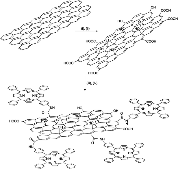 | ||
Scheme 1 A schematic illustration for the preparation of GO with covalently linked H2P. (i) H2SO4/HNO3 (2![[thin space (1/6-em)]](https://www.rsc.org/images/entities/char_2009.gif) :1 v/v), (ii) KClO3, 96 h, (iii) (COCl)2, 80 °C, 24 h, (iv) 5-(4-aminophenyl)-10,15,20-triphenyl-21,23H-porphyrin, THF, r.t., 72 h. :1 v/v), (ii) KClO3, 96 h, (iii) (COCl)2, 80 °C, 24 h, (iv) 5-(4-aminophenyl)-10,15,20-triphenyl-21,23H-porphyrin, THF, r.t., 72 h. | ||
Morphology
Initially, the GO-based hybrid material was studied by AFM and TEM. Tapping mode AFM was applied to identify the morphology of the GO–H2P material (Fig. 1a and Fig. SI, ESI†). Analysis of numerous AFM images revealed the presence of graphene sheets with heights ranging between 1.5–3.5 nm and average lateral dimension of 150 nm. Considering the height of a single GO sheet as 0.8–1.0 nm22 and the added contribution from the grafted porphyrin moiety, the obtained images are representative of single and/or bilayers of exfoliated modified GO sheets. Moreover, TEM images of GO–H2P were obtained and compared with images of intact graphite, thus allowing the observation of multiple-layered GO sheets with various dimensions, most likely overlapped on the peripheral edges (Fig. 1b).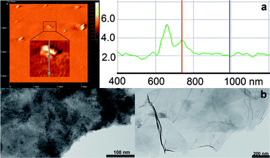 | ||
| Fig. 1 (a) Representative AFM image of GO–H2P and profile analysis showing a height of 1.77 nm for the enlarged region. Section analysis of other regions of the image show height ranges of 1.5–3.5 nm. (b) TEM images of the intact graphite (left panel) and GO–H2P hybrid material (right panel). | ||
Characterization
The formation of GO–H2P was followed by ATR-IR spectroscopy. Initially, in the spectrum of GO, the carbonyl vibration appears at 1716 cm−1, while there are fingerprints at 3616 cm−1 and 3490 cm−1 due to the presence of hydroxyl species at the basal plane of graphene. The covalent linkage of H2P with the acyl chloride activated GO is evident from the presence of a band at 1630 cm−1, which is characteristic for the carbonyl groups of the amide units23 (see Fig. S2, ESI†).Raman spectroscopy was applied to follow the chemical modification of graphite to GO and subsequently to GO–H2P. In a typical Raman spectrum of graphite, the G-band located at 1580 cm−1, related to the vibrations of the sp2 hybridized carbons in the 2-D lattice of graphite24 and the G′-band as a sharp and symmetric band at 2725 cm−1, related to the two phonon double resonance Raman process, are observed (Fig. 2). In the Raman spectrum of GO, the evolution of the D-band at 1345 cm−1, assigned to defects introduced upon the oxidation process is characteristic. Moreover, the G′-band in GO, appears broader and blueshifted, as compared with that of graphite, manifesting indeed the presence of single and/or bilayers of GO sheets25 (cf. AFM image, Fig. 1a and Fig. S1, ESI†). The Raman spectrum of GO–H2P is almost identical to that of GO, thus implying that no further structural perturbation of the graphene skeleton occurred upon treatment of GO with H2P.
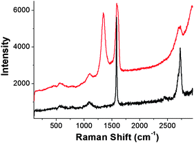 | ||
| Fig. 2 Raman spectra of graphite (black) and GO (red), obtained at 514 nm. | ||
The amount of porphyrin attached onto the graphene sheet was evaluated by thermogravimetric analysis. As compared with the TGA results of pure graphite, which is thermally stable up to 900 °C under nitrogen, and GO which decomposes above 600 °C, after having lost the oxygenated species at 240 °C (i.e. 14.7% weight loss), the 6% weight loss occurred in the temperature range 250–550 °C for the GO–H2P material, is attributed to the decomposition of H2P (Fig. 3).
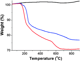 | ||
| Fig. 3 The TGA graphs of graphite (black), GO (blue) and GO–H2P (red), obtained under an inert atmosphere. | ||
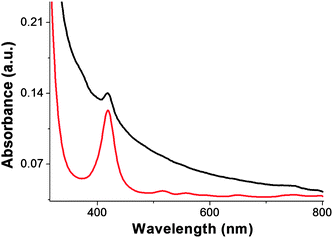
The GO–H2P material forms a stable dispersion in DMF at a concentration not exceeding 1 mg mL−1. The electronic absorption spectrum of GO–H2P in DMF (Fig. 4), shows (i) a broad signal monotonically decreasing from the UV to the visible region, which is attributed to GO and (ii) a characteristic band at 420 nm (Soret-band) corresponding to the covalently grafted H2P units (the Q-bands at 516, 557, 589 and 648 nm were flattened to the base line in the GO–H2P material). Interestingly, the absorption of porphyrin in the GO–H2P material is broadened, shortened and bathochromically shifted (ca. 2 nm) as compared to that of the free H2P, a result that corroborates not only the linkage of porphyrin with the GO sheets but also electronic interactions between the two species (i.e. GO and H2P) in the ground state. These results are in agreement with studies based on other hybrid systems consisting of porphyrins covalently grafted to carbon nanotubes and nanohorns.14,15,26
Photophysics and electrochemistry
Photoluminescence spectroscopy was applied as meaningful means of extending the investigation of electronic interactions of the H2P units with the GO sheets in the excited state. Upon excitation at 418 nm, the characteristic fluorescence emission of H2P at 660 nm and 716 nm in DMF, is significantly quenched in GO–H2P (i.e. measurements performed with matching absorbencies at the excitation wavelength). Moreover, the emission at 660 nm is also blue shifted by ca. 10 nm, mirroring the bathochromic shift observed in the electronic absorption spectra, which appears broadened (Fig. 5). It should be pointed out that, due to interference from the absorption of GO at the excitation wavelength, it is rather difficult to quantify the quenching of the porphyrin emission in the graphene-based hybrid material. Nevertheless, the effective emission quenching of porphyrin in GO–H2P hybrid is indicative of electronic interactions between the singlet excited state of the porphyrin (1H2P*) and GO. Therefore, covalently linked H2P with GO can act as an energy absorbing and electron transporting antennae, while GO acts as an electron acceptor unit, in a hybrid system where the porphyrin moiety resides near to the surface of the GO framework.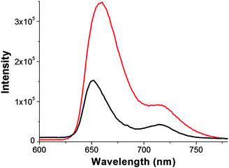 | ||
| Fig. 5 The fluorescence emission spectra of GO–H2P (black) and free H2P (red), obtained in DMF (λexc. = 418 nm). | ||
In the following step, in order to further support the electronic communication between the two species, the photoinduced dynamics of the GO–H2P hybrid excited state were examined by time-resolved spectroscopic techniques. From the fluorescence time-profiles presented in Fig. 6, the fluorescence lifetimes of the photoexcited porphyrin in the GO–H2P were curve-fitted using biexponential decay kinetics, from which lifetimes of 675 ps (50%) and 1600 ps (50%), were evaluated. These values are significantly shorter than the lifetime of the intact porphyrin (2900 ps), thus it is reasonable to assume a charge-separation and/or energy transfer scenario in the GO–H2Pvia (1H2P*).19 Additionally, the above mentioned results also support and corroborate the efficient emission quenching of H2P by the graphene sheets in the GO–H2P hybrids, as observed in the fluorescence intensity quenching and the appreciable blue-shift of the fluorescence peak in the steady-state spectra (cf. Fig. 5). The fluorescence lifetimes (τf), quenching rate constants (kSq) and quantum yields (ΦSq) for charge-separation for the GO–H2P hybrid material are summarized in Table 1. The kSq and ΦSq for GO–H2P were evaluated in DMF as 1.14 × 10⁹s−1 and 0.77, respectively.
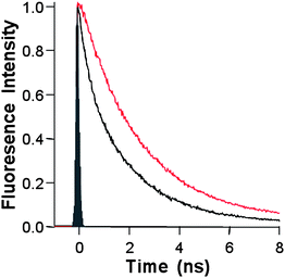 | ||
| Fig. 6 The fluorescence decay profiles of GO–H2P (black) and the free H2P (red), in DMF (λexc. = 408 nm). | ||
| Material | τ f/ps | k S q/s−1 | ΦSq |
|---|---|---|---|
| GO–H2P | 675 (50%) 1600 (50%) | 1.14 × 10⁹ | 0.77 |
| H2P | 2900 (100%) |
The electrochemical redox potentials of the GO–H2P material were studied by cyclic voltammetry (CV) and differential pulsed voltammetry (DPV). From the CV, the oxidation potential of H2P in GO–H2P was found at 0.68 V vs.SCE, cathodically shifted by approximately 100 mV as compared with the free H2P (Fig. 7a). This cathodic shift is attributed to the intra-hybrid GO–H2P electronic interactions that render it considerably easier to oxidise the porphyrin units. From the DPV—which removes the effect of the electrode capacitive charging, resulting in only Faradaic processes and hence much higher signals than other conventional voltammetry methods27—on the reduction site in the negative potentials (Fig. 7b—for the oxidation site, see Fig. S3, ESI†), a weak and broad signal was observed at −0.19 V vs.SCE, which is reasonably attributed to the reduction potential of GO in the GO–H2P material10,28 (i.e. no appreciable reduction of H2P is expected in that potential region, a clearly visible reduction potential of H2P was observed at 0.55 V vs.SCE). The difference between the oxidation potential of H2P and the reduction potential of GO, ca. 0.87 eV, yields the energy gap for the charge-separation state of (GO)˙−–(H2P)˙+. Therefore, the negative free-energy change for the photoinduced charge-separation of GO–H2Pvia the singlet excited state of H2P (1.87 eV), was evaluated to be −1.00 eV, which confirms the thermodynamically favorable formation process of (GO)˙−–(H2P)˙+.
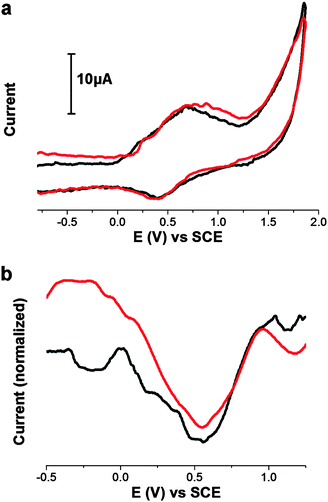 | ||
| Fig. 7 (a) Cyclic voltammogram and (b) differential pulsed voltammogram of reductions, of GO–H2P (black) and free H2P (red). All measurements are obtained in 0.1 M TBAPF6 in DMF, using Ag/AgNO3, as the reference electrode at room temperature and calibrated using Fc/Fc+. | ||
To complement our studies and to follow the outcome of H2P fluorescence quenching and the generation of the new photoproducts in G –H2P, transient absorption measurements were conducted. In this context, by photoexciting the Q-band of H2P with 532 nm short laser light pulses, the population of H2P is directed in the singlet exited states. In the transient absorption spectrum of the GO–H2P hybrid material (Fig. 8), the band absorption in the visible region at 610 nm, is attributed to the one-electron oxidized porphyrin species (H2P)+, albeit depleted due to the scattering of the 532 nm laser light by the dispersed particles overlapping, while the characteristic feature at 450 nm is the triplet–triplet absorption of the porphyrin, which is almost identical to the one observed in the transient absorption spectrum of intact H2P (Fig. S4, ESI†).15,29 Additionally, the bands that appeared in the NIR region are attributed to electrons trapped within the reduced modified graphene sheets, namely (GO)− species30 (depletion was observed near 1100 nm due to the fundamental YAG laser). Further evidence for the latter comes from the absorption spectrum obtained for the electrochemically reduced GO material, showing absorbencies in the NIR region due to the formation of (GO)− species (Fig. S5, ESI†). Therefore, the transient absorption spectrum provides evidence to support the formation of the charge-separated radical ion pair (GO)˙−–(H2P)˙+. Moreover, after light excitation, the decline with time of these transient absorption features signifies the charge-recombination development with return of the radical ion pair back to the electronic ground state.
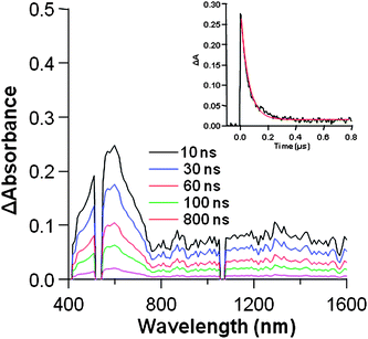 | ||
| Fig. 8 The nanosecond transient absorption spectra of GO–H2P observed at 532 nm (ca. 1 mJ/pulse) laser irradiation in DMF. Inset: absorption-time profiles at 610 nm. | ||
Eventually, the decay profiles for these transient species (inset of Fig. 8 for absorption time-profiles at 610 nm, and Fig. S6, ESI† for absorption time-profiles at 1300 nm) gave a charge-recombination rate constant (kCR) of 1.8 × 10⁷s−1, from which the lifetime of the radical ion pair (τrip) of (GO)−˙–(H2P)+˙ is evaluated to be 56 ns, in DMF. From these nanosecond transient absorption measurements, it is confirmed that the fluorescence quenching of H2P is attributed to the charge-separation generating (GO)−–(H2P)+via1H2P*. In this frame, the kSq and ΦSq values in Table 1 can be put equal to the charge-separation rate constant (kSCS) and charge-separation quantum yield (ΦSCS), respectively. As the kSCS value is larger than kCR, it is feasible to extract the separated charges, electron and hole, for the construction of devices suitable for photovoltaic applications. On the other hand, a reason the kSCS value is larger than for kCR, is that it is difficult to assume the Marcus reorganization energy as it may be rather similar to the ΔGCS value.31
Photoelectrochemical behavior
The emission and transient absorption measurements presented indicate that GO can effectively capture electrons transported from the photoexcited porphyrins. Thus, this ability of GO sheets to capture electrons from porphyrins can be exploited for photovoltaic-based applications. Electrophoretic deposition was applied to fabricate films of graphite onto nanostructured SnO2 films cast onto an optically transparent electrode (OTE/SnO2) and to use them as photoanodes in photoelectrochemical cells with OTE/SnO2/GO–H2P and OTE/SnO2/graphite as the working electrode, platinum wire as the counter electrode and acetonitrile containing 0.5 M LiI and 0.01 M I2 as the redox electrolyte.32 A suspension of the graphite in DMF (2 mL) was transferred to a 1 cm cuvette. For the fabrication of the electrodes, two OTE cut from conducting glass were inserted, and a dc electric field (100 V cm−1) was applied. The graphite from the suspension was driven to the positive electrode surface, and a robust thin film (abbreviated as OTE/SnO2/graphite) was deposited within 2 min. An analogous process was adopted to deposit the GO–H2P nano-assemblies onto OTE/SnO2 (abbreviated as OTE/SnO2/GO–H2P).The steady-state electron absorption spectra of the OTE/SnO2/GO–H2P electrode absorbs incident light effectively in the visible region, and the absorption band extends into the NIR region (see Fig. S7, ESI†). The characteristic Soret-band of the porphyrin unit in the OTE/SnO2/GO–H2P film is identified, however, broadened, as compared with the corresponding Soret-band of the GO–H2P hybrid material in DMF solution (cf. Fig. 4). At this point, it should be mentioned that the broader absorption of the electrode is likely to arise from the clustering effects of porphyrin moieties or electronic interaction between GO and H2P.32
The OTE/SnO2/GO–H2P electrode performance was evaluated by recording the photocurrent density at different incident photon energies. An illustration of the system is depicted on Scheme 2, where the electron is collected at the OTE/SnO2 electrode surface and the hole generated is scavenged by the electrolyte in solution.
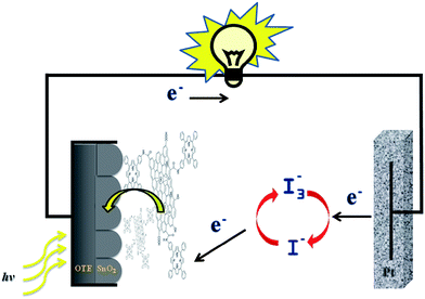 | ||
| Scheme 2 The photoelectrochemical cell based on the GO–H2P hybrid material. | ||
In this context, a net anodic current is generated. In the photoaction spectrum of GO–H2P, the porphyrin is clearly identified as the major photoactive component in the hybrid material and Fig. 9 shows the incident-photo-conversion-efficiency (IPCE) as a function of the excitation wavelength. The IPCE values are calculated by normalizing the photocurrent densities for incident light energy and intensity and by the use of the following expression:33
| IPCE(%) = 100 × 1240 × i/(Win × λ) |
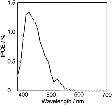 | ||
| Fig. 9 The photocurrent action spectrum of OTE/SnO2/GO–H2P. | ||
Conclusions
In summary, we have presented the synthesis of a new GO–H2P hybrid material following the oxidation of graphite and subsequent condensation reaction with aminoporphyrin. In this manner, porphyrin units have been covalently grafted through robust amide bonds at the periphery of GO sheets and the hybrid material has been fully characterized through spectroscopy, electrochemistry, thermal analysis and microscopy. Moreover, steady-state and time-resolved absorption and emission studies together with electrochemistry have allowed the evaluation of photophysical properties for the hybrid material in terms of charge separation and charge recombination lifetimes, quantum yields and radical ion pairs. In addition, photoelectrochemical cells with GO–H2P electrodes have also been constructed and the IPCE value has been measured. Overall, this is a promising and leading beginning for graphene-based hybrid materials possessing covalently linked photoactive moieties towards the development of novel optoelectronic devices.Acknowledgements
Partial financial support from the EU FP7, Capacities Program, NANOHOST project (GA 201729) and COST network MP0901 NanoTP to N.T. is acknowledged. This work was partially supported by Grant-in-Aids for Scientific Research (No. 21710104 to T.H.).References
- K. S. Novoselov, A. K. Geim, S. V. Morozov, D. Jiang, Y. Zhang, S. V. Dubonos, I. V. Grigorieva and A. A. Firsov, Science, 2004, 306, 666 CrossRef CAS; A. K. Geim and K. S. Novoselov, Nat. Mater., 2007, 6, 183 CrossRef CAS.
- X. Li, X. Wang, L. Zhang, S. Lee and H. Dai, Science, 2008, 319, 1229 CrossRef CAS.
- M. D. Stoller, S. Park, Y. Zhu, J. An and R. S. Ruoff, Nano Lett., 2008, 8, 3498 CrossRef CAS.
- S. Stankovich, D. A. Dikin, G. H. B. Dommett, K. M. Kohlhaas, E. J. Zimney, E. A. Stach, R. D. Piner, S. T. Nguyen and R. S. Ruoff, Nature, 2006, 442, 282 CrossRef CAS; T. Ramanathan, A. A. Abdala, S. Stankovich, D. A. Dikin, M. Herrera Alonso, R. D. Piner, D. H. Adamson, H. C. Schniepp, X. Chen, R. S. Ruoff, S. T. Nguyen, I. A. Aksay, R. K. Prud'Homme and L. C. Brinson, Nat. Nanotechnol., 2008, 3, 327 CrossRef CAS.
- P. Blake, P. D. Brimicombe, R. R. Nair, T. J. Booth, D. Jiang, F. Schedin, L. A. Ponomarenko, S. V. Morozov, H. F. Gleeson, E. W. Hill, A. K. Geim and K. S. Novoselov, Nano Lett., 2008, 8, 1704 CrossRef.
- J. T. Robinson, F. K. Perkins, E. S. Snow, Z. Wei and P. E. Sheehan, Nano Lett., 2008, 8, 3137 CrossRef CAS; C. Shan, H. Yang, J. Song, D. Han, A. Ivaska and L. Niu, Anal. Chem., 2009, 81, 2378 CrossRef CAS.
- S. Park and R. S. Ruoff, Nat. Nanotechnol., 2009, 4, 217 CrossRef CAS; K. P. Loh, Q. Bao, P. K. Ang and J. Yang, J. Mater. Chem., 2010, 20, 2277 RSC.
- S. Stankovich, R. D. Piner, X. Chen, N. Wu, S. T. Nguyen and R. S. Ruoff, J. Mater. Chem., 2006, 16, 155 RSC; S. Niyogi, E. Bekyarova, M. E. Itkis, J. L. McWilliams, M. A. Hamon and R. C. Haddon, J. Am. Chem. Soc., 2006, 128, 7720 CrossRef CAS; S. Stankovich, D. A. Dikin, R. D. Piner, K. A. Kohlhaas, A. Kleinhammes, Y. Jia, Y. Wu, S. T. Nguyen and R. S. Ruoff, Carbon, 2007, 45, 1558 CrossRef CAS; Y. Xu, H. Bai, G. Lu, C. Li and G. Shi, J. Am. Chem. Soc., 2008, 130, 5856 CrossRef CAS; S. Park, J. An, R. D. Piner, I. Jung, D. Yang, A. Velamakanni, S. T. Nguyen and R. S. Ruoff, Chem. Mater., 2008, 20, 6592 CrossRef CAS; D. Li, M. B. Muller, S. Gilje, R. B. Kaner and G. G. Wallace, Nat. Nanotechnol., 2008, 3, 101 CrossRef CAS; G. Eda, G. Fanchini and M. Chhowalla, Nat. Nanotechnol., 2008, 3, 270 CrossRef CAS; Y. Si and E. T. Samulski, Nano Lett., 2008, 8, 1679 CrossRef CAS; V. C. Tung, M. J. Allen, Y. Yang and R. B. Kaner, Nat. Nanotechnol., 2009, 4, 25 CrossRef CAS; S. Park, J. An, I. Jung, R. D. Piner, S. J. An, X. Li, A. Velamakanni and R. S. Ruoff, Nano Lett., 2009, 9, 1593 CrossRef CAS; Y. Zhu, A. L. Higginbotham and J. M. Tour, Chem. Mater., 2009, 21, 5284 CrossRef CAS.
- J. Zhang, H. Yang, G. Shen, P. Cheng, J. Zhang and S. Guo, Chem. Commun., 2010, 46, 1112 RSC; J. Gao, F. Liu, Y. Liu, N. Ma, Z. Wang and X. Zhang, Chem. Mater., 2010, 22, 2213 CrossRef CAS; M. J. Fernandez-Merino, L. Guardia, J. I. Paredes, S. Villar-Rodil, P. Solis-Fernandez, A. Martinez-Alonso and J. M. D. Tascon, J. Phys. Chem. C, 2010, 114, 6426 CrossRef CAS.
- Y. Shao, J. Wang, M. Engelhard, C. Wang and Y. Lin, J. Mater. Chem., 2010, 20, 743 RSC.
- M. J. McAllister, J.-L. Li, D. H. Adamson, H. C. Schniepp, A. A. Abdala, J. Liu, M. Herrera-Alonso, D. L. Milius, R. Car, R. K. Prud'homme and I. A. Aksay, Chem. Mater., 2007, 19, 4396 CrossRef CAS; X. Li, G. Zhang, X. Bai, X. Sun, X. Wang, E. Wang and H. Dai, Nat. Nanotechnol., 2008, 3, 538 CrossRef CAS.
- A. Vadivel Murugan, T. Muraliganth and A. Manthiram, Chem. Mater., 2009, 21, 5004 CrossRef CAS; J. Che, L. Shen and Y. Xiao, J. Mater. Chem., 2010, 20, 1722 RSC.
- J. I. Paredes, S. Villar-Rodil, A. Martićnez-Alonso and J. M. D. Tascoćn, Langmuir, 2008, 24, 10560 CrossRef CAS.
- M. Alvaro, P. Atienzar, P. de la Cruz, J. L. Delgado, V. Troiani, H. Garcia, F. Langa, A. Palkar and L. Echegoyen, J. Am. Chem. Soc., 2006, 128, 6626 CrossRef CAS; F. Cheng and A. Adronov, Chem. Mater., 2006, 18, 5389 CrossRef CAS; S. Campidelli, C. Sooambar, E. Lozano Diz, C. Ehli, D. M. Guldi and M. Prato, J. Am. Chem. Soc., 2006, 128, 12544 CrossRef CAS.
- G. Pagona, A. S. D. Sandanayaka, Y. Araki, J. Fan, N. Tagmatarchis, G. Charalambidis, A. G. Coutsolelos, B. Boitrel, M. Yudasaka, S. Iijima and O. Ito, Adv. Funct. Mater., 2007, 17, 1705 CrossRef CAS; C. Cioffi, S. Campidelli, C. Sooambar, M. Marcaccio, G. Marcolongo, M. Meneghetti, D. Paolucci, F. Paolucci, C. Ehli, G. M. A. Rahman, V. Sgobba, D. M. Guldi and M. Prato, J. Am. Chem. Soc., 2007, 129, 3938 CrossRef.
- D. M. Guldi, Phys. Chem. Chem. Phys., 2007, 9, 1400 RSC; V. Sgobba and D. M. Guldi, J. Mater. Chem., 2008, 18, 153 RSC; V. Sgobba and D. M. Guldi, Chem. Soc. Rev., 2009, 38, 165 RSC.
- X. Wang, L. Zhi and K. Mullen, Nano Lett., 2008, 8, 323 CrossRef CAS.
- Z. Liu, Q. Liu, Y. Huang, Y. Ma, S. Yin, X. Zhang, W. Sun and Y. Chen, Adv. Mater., 2008, 20, 3924 CrossRef CAS.
- Z.-B. Liu, Y.-F. Xu, X.-Y. Zhang, X.-L. Zhang, Y.-S. Chen and J.-G. Tian, J. Phys. Chem. B, 2009, 113, 9681 CrossRef CAS; Y. Xu, Z. Liu, X. Zhang, Y. Wang, J. Tian, Y. Huang, Y. Ma, X. Zhang and Y. Chen, Adv. Mater., 2009, 21, 1275 CrossRef CAS.
- N. Karousis, S. P. Economopoulos, E. Sarantopoulou and N. Tagmatarchis, Carbon, 2010, 48, 854 CrossRef CAS.
- J. R. Lomeda, C. D. Doyle, D. V. Kosynkin, W.-F. Hwang and J. M. Tour, J. Am. Chem. Soc., 2008, 130, 16201 CrossRef CAS.
- C. Gómez-Navarro, R. T. Weitz, A. M. Bittner, M. Scolari, A. Mews, M. Burghard and K. Kern, Nano Lett., 2007, 7, 3499 CrossRef CAS; H. A. Becerril, J. Mao, Z. Liu, R. M. Stoltenberg, Z. Bao and Y. Chen, ACS Nano, 2008, 2, 463 CrossRef CAS.
- C. Tang, A. Tracz, M. Kruk, R. Zhang, D.-M. Smilgies, K. Matyjaszewski and T. Kowalewski, J. Am. Chem. Soc., 2005, 127, 6918 CrossRef CAS.
- L. Ballester, A. M. Gil, A. Gutierrez, M. F. Perpinan, M. T. Azcondo, A. E. Sanchez, E. Coronado and C. J. Gomez-Garcia, Inorg. Chem., 2000, 39, 2837 CrossRef CAS.
- Z. Ni, Y. Wang, T. Yu and Z. Shen, Nano Res., 2008, 1, 273 CrossRef CAS.
- Z.-B. Liu, J.-G. Tian, Z. Guo, D.-M. Ren, F. Du, J.-Y. Zheng and Y.-S. Chen, Adv. Mater., 2008, 20, 511 CrossRef CAS; G. Pagona, A. S. D. Sandanayaka, T. Hasobe, G. Charalambidis, A. G. Coutsolelos, M. Yudasaka, S. Iijima and N. Tagmatarchis, J. Phys. Chem. C, 2008, 112, 15735 CrossRef CAS.
- A. Bard and L. Faulkner, Electrochemical Methods: Fundamentals and Applications, 2nd edn, John Wiley and Sons: New York, 2001 Search PubMed.
- R. S. Sundaram, C. Gómez-Navarro, K. Balasubramanian, M. Burghard and K. Kern, Adv. Mater., 2008, 20, 3050 CrossRef CAS; G. K. Ramesha and S. Sampath, J. Phys. Chem. C, 2009, 113, 7985 CrossRef CAS; M. Zhou, Y. Wang, Y. Zhai, J. Zhai, W. Ren, F. Wang and S. Dong, Chem.–Eur. J., 2009, 15, 6116 CrossRef CAS.
- D. Kuciauskas, S. Lin, G. R. Seely, A. L. Moore, T. A. Moore, D. Gust, T. Drovetskaya, C. A. Reed and P. D. W. Boyd, J. Phys. Chem., 1996, 100, 15926 CrossRef CAS; L. R. Sutton, M. Scheloske, K. S. Pirner, A. Hirsch, D. M. Guldi and J.-P. Gisselbrecht, J. Am. Chem. Soc., 2004, 126, 10370 CrossRef CAS; F. Oswald, D.-M. S. Islam, Y. Araki, V. Troiani, R. Caballero, P.d. l. Cruz, O. Ito and F. Langa, Chem. Commun., 2007, 4498 RSC; A. L. Schumacher, A. S. D. Sandanayaka, J. P. Hill, K. Ariga, P. A. Karr, Y. Araki, O. Ito and F. D'Souza, Chem.–Eur. J., 2007, 13, 4628 CrossRef CAS; A. S. D. Sandanayaka, O. Ito, T. Tanaka, H. Isobe, E. Nakamura, M. Yudasaka and S. Iijima, New J. Chem., 2009, 33, 2261 RSC; A. S. D. Sandanayaka and O. Ito, J. Porphyrins Phthalocyanines, 2009, 13, 1017 CrossRef CAS.
- S. Kumar, M. Anija, N. Kamaraju, K. S. Vasu, K. S. Subrahmanyam, A. K. Sood and C. N. R. Rao, Appl. Phys. Lett., 2009, 95, 191911 CrossRef.
- K. Saito, V. Troiani, H. Qiu, N. Solladié, T. Sakata, H. Mori, M. Ohama and S. Fukuzumi, J. Phys. Chem. C, 2007, 111, 1194 CrossRef CAS; R. Chitta, A. S. D. Sandanayaka, A. L. Schumacher, L. D'Souza, Y. Araki, O. Ito and F. D'Souza, J. Phys. Chem. C, 2007, 111, 6947 CrossRef CAS; F. D'Souza, R. Chitta, A. S. D. Sandanayaka, N. K. Subbaiyan, L. D'Souza, Y. Araki and O. Ito, Chem.–Eur. J., 2007, 13, 8277 CrossRef CAS.
- S. Barazzouk, S. Hotchandani, K. Vinodgopal and P. V. Kamat, J. Phys. Chem. B, 2004, 108, 17015 CrossRef CAS; T. Hasobe, H. Imahori, S. Fukuzumi and P. V. Kamat, J. Phys. Chem. B, 2003, 107, 12105 CrossRef CAS.
- T. Hasobe, Y. Kashiwagi, M. A. Absalom, J. Sly, K. Hosomizu, M. J. Crossley, H. Imahori, P. V. Kamat and S. Fukuzumi, Adv. Mater., 2004, 16, 975 CrossRef CAS; T. Hasobe, P. V. Kamat, M. A. Absalom, Y. Kashiwagi, J. Sly, M. J. Crossley, K. Hosomizu, H. Imahori and S. Fukuzumi, J. Phys. Chem. B, 2004, 108, 12865 CrossRef CAS.
- The main reason for the difference between IPCE (Fig. 9) and absorption (Fig. S7) spectra is due to the measurement setup in the electrolyte system (I −/I3−redox couple in acetonitrile) since the incident light is absorbed by the electrolyte solution. In the long wavelength region, the large scattering effect may have an effect on the low IPCE value. See the following related papers: T. Hasobe, S. Fukuzumi and P. V. Kamat, J. Phys. Chem. B, 2006, 110, 25477 Search PubMed; T. Hasobe, S. Fukuzumi and P. V. Kamat, Angew. Chem., Int. Ed., 2006, 45, 755 CrossRef CAS.
Footnote |
| † Electronic supplementary information (ESI) available: Additional microscopy and spectroscopy data. See DOI: 10.1039/c0jm00991a |
| This journal is © The Royal Society of Chemistry 2011 |