 Open Access Article
DOI:
10.1039/B901606F
(Paper)
Faraday Discuss., 2010,
144, 71-92
Kinetic Monte Carlo simulations of flow-induced nucleation in polymer melts
Received
26th January 2009
, Accepted 27th February 2009
First published on
15th August 2009
Abstract
We derive a kinetic Monte Carlo algorithm to simulate flow-induced nucleation in polymer melts. The crystallisation kinetics are modified by both stretching and orientation of the amorphous chains under flow, which is modelled by a recent non-linear tube theory. Rotation of the crystallites under flow is modelled by a simultaneous Brownian dynamics simulation. Our kinetic Monte Carlo approach is highly efficient at simulating nucleation and is tractable even at low under-cooling. The simulations predict enhanced nucleation under both transient and steady state shear. Furthermore the model predicts the growth of shish-like elongated nuclei for sufficiently fast flows, which grow by a purely kinetic mechanism.
1 Introduction
Semi-crystalline polymers make up a very significant fraction of the world's production of synthetic polymers. Unlike simple molecules, the connectivity of polymer molecules causes them to crystallise into a composite structure of crystalline and amorphous regions. The proportion of amorphous and crystalline material, along with the arrangement and orientation of the crystals, is collectively known as the morphology. The crystal morphology strongly influences strength, toughness, permeability, surface texture, transparency and almost any other property of practical interest. Furthermore, polymer crystallisation is radically influenced by the types of flow that are ubiquitous in polymer processing. Such flows drastically enhance the rate at which polymers crystallise and have a profound effect on their morphology. Flow distorts the configuration of polymer chains and, it is believed, this distortion breaks down the kinetic barriers to crystallisation and directs the resulting morphology. However, the molecular mechanisms underlying these processes have yet to be established. As a result, there is no predictive molecular model of flow-induced crystallisation (FIC). The impact of such a model on the polymer industry would be considerable since it would allow control over the crystalline properties of polymer products by simply tailoring their processing conditions.
It has long been known that flow can radically enhance the rate of polymer nucleation and can cause the formation of highly aligned, elongated crystals, known as shish-kebabs.1 There have been numerous recent experimental studies, focusing mainly on entangled polymers. These have quantified the effect of flow on nucleation,2 have illuminated details of shish-kebab formation3–5 and have highlighted the role of blend concentration,6 molecular architecture7 and molecular relaxation time.8 Almost all of these experiments have been performed at low undercooling, where crystallisation in the absence of flow is too slow to be measured, as often the most pronounced flow-induced effects are seen in this temperature regime.
Existing theoretical approaches for FIC fall broadly into two extremes of coarse-graining, highly simplified semi-empirical models9–13 and detailed simulations at the level of molecular dynamics14,15 or simulations with slightly higher coarse-graining.16–19 Simplified coarse-grained models follow a semi-empirical approach,9–13 containing some molecular elements but also requiring ad hoc arguments to describe experimental phenomena. Such approaches also require numerous pre-averaging or closure approximations, which neglect the delicate coupling between the underlying stochastic processes. Finally, these models invariably use oversimplified flow models that cannot predict the full range of molecular deformation in a melt. The accuracy of the constitutive model is tacitly assumed to be ensured by simple parameter fitting to rheological measurements. However, this approach cannot accurately model the melt's high molecular weight tail, which is known to dominate the FIC behaviour.6–8 At the opposite extreme of coarse-graining, molecular dynamics (MD) simulations14,15 provide a more rigorous approach to crystallisation. While these MD simulations have provided much useful information on the growth phase, they can only access a limited range of timescales and so are not well-suited to model nucleation. Faster alternatives, with higher coarse-graining, include kinetic Monte Carlo16–18 and Langevin dynamics simulations.19 Nevertheless, these simulations still have difficulty modelling primary nucleation, forcing them to focus on high degrees of undercooling. In contrast, recent experiments show that insight into low undercooling is essential to both a fundamental and practical understanding of FIC,3,5,7,8 as the most pronounced flow-induced effects occur at these temperatures. Finally, the algorithms for predicting the effect of flow on the non-crystalline chain configurations used in these simulations has not been verified against relevant measurements such as mechanical stresses20 and neutron scattering.21 It appears that, to progress, an intermediate level of coarse-graining, between semi-empirical approaches and detailed simulations, is required.
In this paper we develop a coarse-grained simulation algorithm for flow-induced nucleation in polymers. The algorithm is intended to capture the dominant physical processes while remaining tractable at all relevant temperatures, including low undercooling. Simulating nucleation is problematic, especially at low undercooling, because it is a rare event. Much simulation time can be spent resolving the evolution of small nuclei, far from the critical size. In contrast to previous Monte Carlo approaches16–18 we address this issue by using a kinetic Monte Carlo algorithm with variable step size,22 known in some fields as the Gillespie algorithm.23 Although, this method has successfully been applied to quiescent crystal growth in dilute polymers,24 its intrinsically adaptive nature is especially suited to nucleation; large timesteps are automatically taken when the nucleus is small whereas larger nuclei receive more time resolution. In addition we use a recently derived molecular flow model,25 which has been extensively validated against data from non-crystalline polymer fluids under strong flow for both mechanical stress20,25–27 and small angle neutron scattering.21,28–30
2 Simulation algorithm
Our coarse-grained simulation for flow induced crystal nucleation in polymer melts aims to describe how bulk flow affects nucleation density, nucleus aspect ratio and nucleus orientation. The algorithm tracks the time evolution of three processes. The first is stretching and orientation of the amorphous chains due to flow. This is calculated using the Graham-Likhtman and Milner-McLeish (GLaMM) model.25 The second part is the attachment and detachment of chain segments to the nucleus, which were modelled by a kinetic Monte Carlo simulation. The final part is rotation of the crystal nucleus by the bulk flow, and this is tracked by Brownian dynamics simulation.
The amorphous chain stretching is computed first for the whole simulation time, through a single deterministic run of the GLaMM model, the results of which are stored to provide modified kinetics in the subsequent nucleation simulations. The Monte Carlo simulations and the Brownian dynamics rotation simulations are then run concurrently, with multiple runs being used to resolve the statistics. The effect of crystallisation on the amorphous chain dynamics is neglected and, thus, information from the nucleation process is not fed-back into the model for the amorphous chain dynamics. While this may seem to be a crude approximation, experiments on entangled star polymers are beginning to indicate that star arm relaxation is quite similar to linears under non-linear flow,31,32 justifying somewhat this assumption for chains participating in a single crystallite. Also essential to the model derivation is the separation of timescales between the local crystallisation dynamics τ0 and chain dynamics at the entanglement lengthscale τe. We denote this ratio of the flow and crystallisation timescales ![[scr S, script letter S]](https://www.rsc.org/images/entities/char_e532.gif) = τe/τ0. Local crystallisation is taken to be fast compared to the Rouse time of an entanglement segment (τ0 << τe). Also, although the flow rate
= τe/τ0. Local crystallisation is taken to be fast compared to the Rouse time of an entanglement segment (τ0 << τe). Also, although the flow rate ![[small gamma, Greek, dot above]](https://www.rsc.org/images/entities/i_char_e0a2.gif) is non-linear, it will be small compared to the entanglement relaxation time (τe < 1).
is non-linear, it will be small compared to the entanglement relaxation time (τe < 1).
2.1 The GLaMM model
In the GLaMM model a linear chain is divided into Z entanglement segments, each containing Ne Kuhn steps (“monomers”) of length b. The GLaMM model computes the following tube tangent correlation function,| |  | (1) |
where R(s) is the space-curve describing the tube shape, s = 0…Z is a continuous variable, labelling tube segments and all lengths are measured in terms of  , which is the tube diameter. The numerical solution of the GLaMM model provides f(s,s) for each entanglement segment. This tangent vector correlation f(s,s) is effectively the local end-to-end vector correlation of each tube segment
  since r = ΔR and Δs = 1. By this method the GLaMM model provides a set of microscopic strains for each subchain through fi, where i labels the tube segment number, running from 0 to Z (see Fig. 1). Finite chain extensibility is included by replacing the Gaussian spring force with Cohen's approximation33 for the non-linear spring force. We use Ne = 100 throughout this paper.
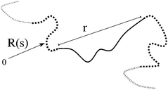 |
| | Fig. 1 The end-to-end vector of a tube segment, which defines the microscopic strain  . . | |
2.1.1 Segment free energy and orientation.
The deformation of the amorphous chains, contained in f, modifies the nucleation kinetics in two ways: the increase in monomer free energy upon stretching reduces the entropic penalty for crystallisation; and monomer alignment modifies the probability of compatible alignment with the nucleus. In appendix A we show that the change in elastic free energy, ΔFel, and the distribution of monomer orientations, w(θ), for a chain subjected to the ensemble average constraint f = 〈rr〉 can be accurately approximated by essentially the expressions for a fixed end-to-end vector with |r| replaced by  ,
,| | 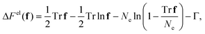 | (2) |
| |  | (3) |
where ![[script L]](https://www.rsc.org/images/entities/char_e144.gif) −1 is the inverse Langevin function, Γ is a constant chosen such that ΔFel = 0 for an equilibrium coil and θ is the angle between the monomer and the principle axis of f. We use Cohen's approximation for the inverse Langevin function,33
−1 is the inverse Langevin function, Γ is a constant chosen such that ΔFel = 0 for an equilibrium coil and θ is the angle between the monomer and the principle axis of f. We use Cohen's approximation for the inverse Langevin function,33| |  | (4) |
2.2 Description of the nucleus
In our coarse-grained simulations we take the minimal nucleus description required to model anisotropic nucleation. The nucleus comprises of a collection of crystallised “monomers” (Kuhn steps) arranged in stems. Each stem is formed from a single chain and the simulation tracks the monomer number of the top and bottom crystallised monomer in each stem (ntop, nbot). This defines the total number of stems Ns and the total number of monomers NT. We assume the nucleus to be spheroidal and use NT and Ns to provide the two radii. We take the crystallised Kuhn segments dimensions to be bl × bw × bw, with the bl length always parallel to the spheroid polar radius L (see Fig. 2). Thus equatorial radius W is given by| |  | (5) |
since the cross sectional area about W is πW2 and this area contains Ns stems. The volume is determined by the total number of monomersThe polar radius L is obtained from the total volume (V = 4/3πLW2), leading to| |  | (7) |
Later on we will require the crystal aspect ratio ρ = L/W,| |  | (8) |
where  is a dimensionless prefactor that controls the aspect ratio for a given Ns and NT. We also simulate the nucleus orientation through
 ![[v with combining circumflex]](https://www.rsc.org/images/entities/b_char_0076_0302.gif) , a unit vector parallel to the nucleus polar radius.
, a unit vector parallel to the nucleus polar radius.
 |
| | Fig. 2 Definition of the spheroid nucleus, along with the dimensions of a single Kuhn segment. | |
2.2.1 Surface area.
The surface area for a spheroid is computed as follows. The ellipticity ε for prolate and oblate spheroids in terms of ar is| |  | (9) |
For a prolate spheroid the surface area, S is then given by| |  | (10) |
and for an oblate spheroid| |  | (11) |
2.2.2 Nucleus free energy.
As in classical nucleation theory the nucleus free energy is a balance of the free energy of crystallisation proportional to the nucleus volume with a free energy penalty proportional to the spheroid surface area, ![[scr F, script letter F]](https://www.rsc.org/images/entities/char_e141.gif) *nuc(NT,Ns) = −ε*BV + µ*SS, where ε*B and µ*S are the dimensional bulk free energy per unit volume and surface free energies per unit area, respectively. This can be rewritten as
*nuc(NT,Ns) = −ε*BV + µ*SS, where ε*B and µ*S are the dimensional bulk free energy per unit volume and surface free energies per unit area, respectively. This can be rewritten as| | nuc(NT,Ns) = −εBNT + µS![[S with combining tilde]](https://www.rsc.org/images/entities/i_char_0053_0303.gif) , , | (12) |
where  ,
,  ,
,  and S = b2w. These dimensionless parameters control the free energy landscape of the nucleation process. For the remainder of this paper all free energies will be expressed in units of kBT. Note that, from the definitions above, the free energy is determined by just the number of stems, total number of monomers and the aspect ratio parameter ar.
2.3 Kinetic Monte Carlo moves
In the kinetic Monte Carlo simulations two types of basic moves are possible, stem addition and stem lengthening, both of which add a single monomer (see Fig. 3) and have a corresponding reverse move.
 |
| | Fig. 3 The basic Monte Carlo moves of stem addition and stem lengthening. | |
2.3.1 Stem lengthening.
Stem lengthening involves attaching a new monomer to the top or bottom of the crystal and so increasing the length of an existing stem. The number of monomers increases, but the number of stems remains fixed. Thus, the change in free energy upon adding (+) and removing (−) a monomer from an existing stem is| | | Δ+length = (NT + 1,Ns) − (NT,Ns), | (13) |
| | | Δ−length = (NT,Ns) − (NT − 1,Ns). | (14) |
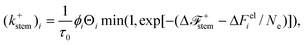
The corresponding move rates k are| |  | (15) |
| |  | (16) |
where τ0 is the timescale of a basic crystallisation step, which can be thought of as an activation energy barrier for hopping between crystal states. This timescale is assumed to be constant, regardless of the shape or size of the nucleus. Each stem contributes four moves to the total rate sum, addition and removal at both the top and bottom of the stem. Thus the contribution from stem lengthening, per stem, to the total sum over rates is| |  | (17) |
If a stem contains only one monomer then the removal move is counted as stem removal and so klength−top and klength−bot are both set to zero. On a successful lengthening move the added monomer is always the next monomer along the chain that forms the stem as the stem “zips-up” the chain. Thus after a lengthening move the appropriate monomer number at the top or bottom of the stem (ntop or nbot) is incremented up or down.
2.3.2 Stem addition.
Stem addition involves attaching a new stem to the side of the nucleus. Both the number of stems and the number of monomers increase by one, so the change in free energy is| | | Δ+stem = (NT + 1,Ns + 1) − (NT,Ns), | (18) |
| | | Δ−stem = (NT,Ns) − (NT − 1,Ns − 1). | (19) |
Similarly to stem lengthening the basic move rates are| |  | (20) |
| |  | (21) |
For quiescent simulations the monomer number of the newly attached monomer can be chosen randomly from any point along the attached chain.
The rate of stem addition will be proportional to the nucleus surface area available to attach new stems. As shown in Fig. 4 there will be substantial excluded volume from the dangling amorphous chains around the nucleus, which prevents stem addition across much of the nucleus. We assume that stem addition is restricted to a band around the spheroid equator, thus the area available for stem addition fadd depends on the equatorial circumference, and is given by
| |  | (22) |
where
a is a constant of proportionality. A value of
a = 0.4 gives spherical nuclei in the quiescent limit. The stem removal rate is set to obey detailed balance. Therefore only stems containing a single monomer are candidates for a stem removal move and these have a basic removal rate,
k−stem. This rate is multiplied by a factor of
fadd(
Ns − 1)/
Ns, which is the probability that the given stem is at the surface of the
nucleus.
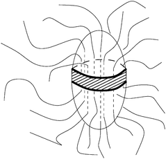 |
| | Fig. 4 Available surface area for stem addition. | |
2.3.3 Effect of flow.
As discussed above, flow modifies the crystallisation kinetics because chain stretching reduces the entropic penalty for crystallisation and chain orientation changes the probability of compatible alignment between the nucleus and any attaching monomers. To account for chain stretching, the change in chain free energy per monomer on stretching is subtracted from the free energy change of a Monte Carlo move. We deal with orientation with a similar approach to ref. 12. We assume that, in order to attach to the nucleus, the candidate monomer must be oriented within a solid tolerance angle Ω of the nucleus orientation. All monomers outside this angle are unable to attach. If Ω is small then the fraction of monomers within this angle is w(θ)Ω, where θ is the angle between the nucleus polar radius and the sub-chain principle strain axis.
Flow causes a linear chain to stretch and align by different amounts at different points along its contour. Thus, even for a monodisperse melt we must deal with a distribution of segment types, with varying degrees of stretch. We take a melt containing S different species, with species i having volume fraction ϕi. For a monodisperse polymer of Z entanglements there are Z species, each with concentration ϕi = 1/Z. The GLaMM model provides f = 〈rr〉 for each species, from which we compute the change in elastic free energy ΔFeli and the fraction of monomers in species i that are compatibly aligned with the nucleus Θi, using eqn (2) and (3) for each species i.
With these modifications the rate of stem attachment for species i becomes
| |  | (23) |
where Δ
Feli is the elastic energy of species
i, Θ
i = 4π
w(
θi) to give agreement with
eqn (20) in the quiescent limit, and a constant of ln(
Ω/4π) has been added to ε
B.
Similarly, the rate of removing stem j becomes
| |  | (24) |
where Δ
Felj is the elastic energy of the monomer species in stem
j. Note that there are no concentration terms for the removal rate.
The rate of lengthening moves at the top of stem j is given by
| | 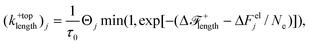 | (25) |
where Δ
Felj and Θ
j are calculated for the species of the next monomer to be added along the chain at the top of stem
k, which is
ntop + 1. Note that for stem lengthening only the next monomer along the chain forming the stem can crystallise. The concentration of this monomer at the
nucleus surface where the lengthening event occurs is taken to be unity, hence the species concentration
ϕj does not appear in
eqn (25). The effective concentration due to relative alignment between the crystal and the chain is included since correct alignment with of the monomer still required. The lengthening rate from the bottom of the stem is calculated similarly. The removal rate from the top of stem
j is given by
| |  | (26) |
where Δ
Fel is calculated for the monomer at the top of stem
j. Note that, as before, the concentrations,
ϕj and Θ
j play no part in the detachment moves. Also, if the stem has only one remaining monomer then the move becomes a stem removal move and is accounted for in
eqn (24). The removal rate from the bottom of the stem is calculated similarly.
2.3.4 Sum over all move rates.
The variable time step kinetic Monte Carlo algorithm requires a sum over all possible moves.22,23 This sum can be written as| |  | (27) |
The first term is a sum over all species and corresponds to stem addition; the second is a sum over all stems and accounts for stem removal; the final sum is over all stems and accounts for lengthening and shortening of each stem.
2.4 Kinetic Monte Carlo time-stepping
With the sum over all possible moves KTotal computed from eqn (27), a kinetic Monte Carlo timestep can be taken. A single move is performed at random, with the probability of each move being picked being weighted by its rate. That is, the probability of move i is,| |  | (28) |
If the move is a stem attachment move, the species and entanglement segment number are known, but the exact monomer to be attached is not and the attached monomer is chosen randomly and uniformly from all monomers in the given entanglement segment. Finally, time is incremented by a stochastically determined interval given by| |  | (29) |
where ζ is chosen uniformly on 0, 1.23 As time proceeds the amorphous chain configuration changes, as pre-calculated by the GLaMM model. For a timestep of Δt, the GLaMM configuration is incremented forward an interval of Δt/S. Then the values of ΔFiel and Θi are updated, and the change in free energy of the moves recalculated.
2.4.1 Dummy Monte Carlo move.
For particularly small nuclei with high energy barriers the sum over possible moves can be very small. In this case the chain deformation may be evolving faster than the Monte Carlo time step and so will need to be updated more frequently. Although kinetic Monte Carlo algorithms are available for time-dependent barriers22 we use a simple solution at this stage. We allow a dummy Monte Carlo move with rate k0. If this dummy move is selected the crystal configuration is not changed, but time is still incremented and then the tube configuration can be updated. We choose k0 to be similar to the rate at which the tube configuration evolves, namely 1/τe, to ensure that the tube configuration is updated sufficiently often. For large enough k0 the simulation results are independent of k0 and all results presented herein are converged with respect to increases in k0.
2.5 Brownian dynamics rotation algorithm
After the kinetic Monte Carlo timestep, the rotational dynamics of the nucleus under flow are iterated over Δt, using a Brownian dynamics algorithm.
2.5.1 Convection term.
The rotation rate of a dilute rigid spheroid in a Newtonian liquid is given by Leal and Hinch34 using the Jeffery algorithm.35 A volume conserving deformation, with a velocity gradient tensor κ, can be split into a symmetric and antisymmetric part| | | κ = E + Ω, ET = E, ΩT = −Ω. | (30) |
The bulk flow causes , a unit vector parallel to the nucleus polar radius, to evolve according to| |  | (31) |
where G is the shape factor. For a spheroid of aspect ratio ρ this is given by| |  | (32) |
Thus for a timestep Δt the convection term is computed first from  .
.
2.5.2 Brownian rotation step.
For the Brownian diffusion step, an axis of rotation is chosen by generating a random unit vector, û. Then a random angle ϕ is generated from a Gaussian distribution with the following moments,| |  | (33) |
where τrot is the crystal rotation relaxation time, related to the rotational diffusion constant by Drot = 1/τrot. The crystal vector is then rotated through an angle ϕ around the axis û, using the rotation formula| | | (t + Δt) = cosϕ + û(û·)(1 − cosϕ) + ( × û)sinϕ. | (34) |
The rotation relaxation time will increase with both the size and the aspect ratio of the spheroid. Leal and Hinch36 use a result from the Jeffery algorithm,35| |  | (35) |
where ηs is the solvent viscosity, V is the spheroid volume, ρ is the spheroid aspect ratio and| |  | (36) |
The integrals in eqn (36) can both be performed analytically for the two cases ρ > 1 and 0 < ρ < 1. Defining τrot = 1/Drot and using our expression for the nucleus volume (eqn (6)) we obtain| |  | (37) |
There is some uncertainty in the pre-factor in this expression when used in our modelling since the solvent is non-Newtonian, the nucleus is not a perfect spheroid and the dangling amorphous chains attached to the nucleus will contribute some drag. Therefore we replace this pre-factor with an unknown dimensionless parameter α, such thatwhich maintains Jeffery's scaling of the rotational diffusion with volume and aspect ratio and ensures τrot ∼ τ0 when NT = 1.
3 Results
In our kinetic MC simulations we follow a single nucleus beginning with a single monomer. The algorithm is especially effective at simulating nucleation at low undercooling since for small nuclei the sum of rates is small, meaning that large time steps are automatically taken.
3.1 Quiescent results
The simulated quiescent nucleation time can be accurately described by an analytical calculation of the free energy landscape. Without flow the amorphous chains of all species have the same equilibrium configuration and therefore the same move rates. In effect a single species of concentration ϕ = 1 is available to attach to the nucleus. This simplification allows the nucleus free energy to be calculated by the following method. The crystal nucleus is defined by the number of stems, Ns, and the total number of monomers, NT, in the crystal. For each NT and Ns, there will be several ways of distributing the NT monomers amongst the Ns strands, subject to the constraint that each stem must contain at least one monomer. Thus after one monomer has been placed in each stem, the number of ways of distributing the remaining NT − Ns monomers is,| |  | (39) |
Thus the free energy of all possible nuclei with NT monomers and Ns stems is given by f(NT,Ns) = (NT,Ns) − ln(ω(NT,Ns)). In principle, this can be used in a two-dimensional diffusion calculation of the first passage of time for a particle over this two-dimensional barrier. However, below we will show that the simulated nucleation times can be accurately approximated by projecting this landscape onto one degree of freedom, the total number of monomers NT. The partition function ZN for a nucleus of NT monomers is obtained by summing over all possible strand numbers,| |  | (40) |
where nuc(NT,Ns) is given by eqn (12). The total free energy Δf for a nucleus of NT monomers is| | | Δf(NT) = − ln ZN + ln Z1, | (41) |
where the free energy is set to zero for a crystal of one monomer. This free energy can also be extracted from a single long simulation by logging the fractional amount of time spent with each number of total monomers. The fraction of time spent with NT monomers tNT/ttotal is proportional to the Boltzmann factor of Δf,| |  | (42) |
from which Δf(NT) can be obtained. The constant A is set so that Δf(1) = 0. Fig. 5 shows the agreement between the calculated and simulated free energies and illustrates how the critical nucleus size n* and the nucleation barrier Δf* can be extracted from these calculations. In these simulations, moves that grow the nucleus beyond some maximum number of monomers Nmax > n* are prevented to allow good resolution of the landscape around n*.
 |
| | Fig. 5 Comparison of calculated and simulated quiescent free energy landscape for two sets of parameters. εB = 0.3 in both cases and µS = 0.25, 0.22 for a and b, respectively. | |
A series of simulations provides the nucleation time τN, which is taken as the first time the polar and equatorial radii simultaneously exceed the critical radius  . The average simulated nucleation time is well described by the Boltzmann factor of the nucleation barrier, 〈τN〉 = τ0exp(Δf*), over a wide range of free energy parameters, as shown in Fig. 6. Fig. 6 also illustrates the efficiency of the algorithm at simulating nucleation even for very large nucleation barriers. We obtained good statistics for nucleation over a barrier of ∼25kBT in ∼50 h on a single processor, giving a nucleation time of ∼1011τ0. Finally, the distribution of nucleation times is Poissonian, meaning that a well-defined quiescent nucleation rate is given by Ṅ0 = 1/〈τN〉.
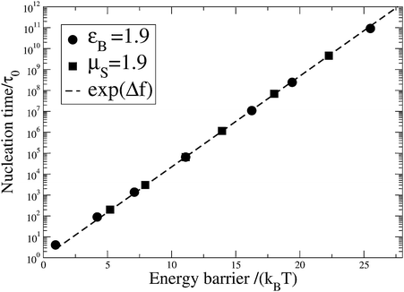 |
| | Fig. 6 Quiescent nucleation rate against nucleation barrier. | |
3.2 Flow results
3.2.1 Enhanced nucleation.
We examine first shear that is slow compared to the nucleus angular relaxation time. By setting α sufficiently small that τn*rot ≪ 1, where τn*rot = αn*H(1)τ0 is the angular relaxation time of a critical nucleus, no significant nucleus alignment occurs before the nucleus reaches the critical size and so alignment effects make no contribution to the nucleation time. We simulate the effect of steady shear by holding the amorphous chains fixed at the steady state GLaMM model predictions for a given shear rate throughout the whole simulation and simulating the average nucleation time. Fig. 7(a) shows the average nucleation time against shear rate for a range of free energy parameters, with the surface energy fixed at µS = 1.9 and the bulk free energy varied to simulate the effect of varying undercooling. Values of εB = 1.9, 1.7 and 1.5 were used, leading to nucleation barriers of Δf* = 11.1, 13.9 and 18.0, respectively. The results as plotted are independent of the separation of shear and crystallisation timescale S. Fig. 7(b) shows the Δf* = 13.9 data on a shorter y-axis, which shows the double exponential behaviour of the nucleation time. All of the data in Fig. 7 have this double exponential shape and can be fitted by the following semi-empirical expression| |  | (43) |
The fitting parameters W*d and W*R are characteristic Weissenberg numbers with respect to the chain reptation and Rouse times, respectively, which define the Weissenberg numbers for the onset of enhanced nucleation due to tube orientation and chain stretch, respectively. The two exponentials correspond to the effect of tube orientation and chain stretching on the nucleation time. The former is controlled by the chain reptation time τd, which was calculated using the Likhtman and McLeish model,37 and the latter is the chain Rouse time τR = Z2τe. The balance of these two contributions is controlled by ΦZ, which is the fractional reduction in the nucleation time due to orientation. ΦZ is also fitted to the simulation data. Tables 1 and 2 contain the parameters obtained by fitting the data in Fig. 7. The Weissenberg numbers depend only on Δf* and not Z, indicating that the contributions from tube orientation and chain stretching scale with Z in the same way as the appropriate relaxation time. Table 1 shows that, while the reptation Weissenberg number has a weak dependence of Δf*, the Rouse Weissenberg number reduces significantly as Δf* rises, indicating that the nucleation becomes more sensitive to chain stretching as the degree of undercooling is reduced. Table 2 shows that ΦZ depends weakly on both Δf*, increasing slightly with both increasing Z and Δf*.
Table 1 Weissenberg numbers used to fit the steady state nucleation results
| Δf |
W
*
d
|
W
*
R
|
| 11.1 |
6.7 |
41.5 |
| 13.9 |
6.9 |
31.1 |
| 18.0 |
8.0 |
23.3 |
Table 2 Values of ΦZ obtained by fitting to the steady state nucleation data. ΦZ is the fractional reduction of the nucleation time due to tube alignment for a range of degrees of undercooling and molecular weights
|
Z
|
ΦZ[Δf* = 11.1] |
ΦZ[Δf* = 13.9] |
ΦZ[Δf* = 18.0] |
| 10 |
0.055 |
0.08 |
0.08 |
| 25 |
0.09 |
0.12 |
0.15 |
| 50 |
0.105 |
0.13 |
0.15 |
 |
| | Fig. 7 (a) The steady shear nucleation time against shear rate for a range of chain lengths (Z) and free energy parameters: εB = 1.9 (solid symbols) εB = 1.7 (striped symbols) εB = 1.5 (open symbols). (b) A closer view of the εB = 1.7 data, showing the double exponential behaviour. In both cases the lines are from fitting eqn (43). | |
Fig. 8 shows the effect of nucleus rotation on the nucleation time. The data for Δf = 11.1 with α = 0 is compared with data where α = 110. For the larger value of α the critical nucleus Weissenberg number exceeds 1 for shear rates τe > 0.03, as shown in Fig. 8. Beyond this shear rate the α = 110 data show a progressive departure from the α = 0 data as nucleus alignment now occurs below the critical nucleus size and so contributes to accelerating the nucleation. When nucleus rotation is included the decay of the nucleation time with shear rate is faster than exponential.
 |
| | Fig. 8 Steady state nucleation time with and without the effect of nucleus rotation,  in both cases. in both cases. | |
The simulations can also compute the nucleation time during a transient flow, by updating the chain configuration during the simulations as detailed in section 2.4. A nucleation rate Ṅ can be obtained from these data via
| |  | (44) |
where
n(
t) is the cumulative fraction of successful nucleation events at time
t.
Fig. 9 shows this transient nucleation rate for a 25 entanglement monodisperse linear melt under start-up shear at
τe = 0.1, both with and without
nucleus rotation. The nucleation rate rises from the quiescent value up to a maximum occurring at around the same time as the overshoot in the shear stress, indicating the strong correlation between nucleation rate and chain configuration. When
nucleus alignment is included (
α = 5.0), the overshoot in the nucleation rate is increased as monomer alignment also makes a substantial contribution at this high shear rate. In both cases the transient maximum nucleation rate is a factor of ∼10 higher than the steady state value.
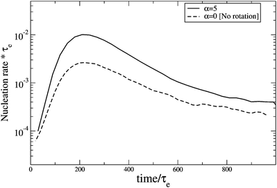 |
| | Fig. 9 Transient nucleation rate for a 25 entanglement monodisperse linear melt with εB = 1.9 and µS = 1.9 under start-up shear at  ; ;  for both curves. for both curves. | |
3.2.2 Shish nuclei.
Our model predicts strongly anisotropic growth under certain conditions. In our simulations shish-like nuclei are especially prevalent in melts of short chains blended with a small amount of very long chains, a system widely used in experiments to enhance shish formation.4–8 We simulated a melt of 15 entanglement chains blended with 2wt% of 52 entanglement chains, with the flow predictions provided by a recent generalisation of the GLaMM model to bimodal blends.30 A surface energy of µS = 2.5 was used as we found that rare nucleation enhances the anisotropy. Fig. 10 shows the average nucleus aspect ratio (L/W) at the point of nucleation, against shear rate. High shear rates produce very elongated nuclei, due to a purely kinetic mechanism where the shish length grows faster than the width. The shish widen by adding new stems for which any monomer from the melt can attach. In contrast, the shish length increases by adding monomers along an existing stem. Therefore the concentration of monomers from stretched segments at the growth surface is greater for lengthening than for widening, provided the nucleus contains a disproportionate number of stretched segments. Fast flow conditions are required for this disparity to overcome the significant surface area cost of elongated nuclei.
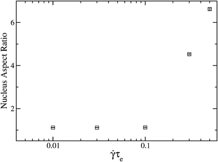 |
| | Fig. 10 Nucleus aspect ratio at the point of nucleation against shear rate for a 2% high molecular weight blend, with α = 5.0 and εB = 3.0 µS = 2.5 and a fixed shear time of 120τe. | |
4 Conclusions
We present an efficient kinetic Monte Carlo algorithm suitable for modelling polymer nucleation even at low undercooling. The configuration of the non-crystalline chains under flow is computed using the deterministic GLaMM model, the nucleation is modelled by a kinetic Monte Carlo algorithm and the nucleus rotation is followed by a Brownian dynamics simulation. Flow modifies the basic Monte Carlo move rates in two ways: the entropic penalty for crystallisation is reduced by the flow induced change in chain free energy and the probability of compatible alignment between the nucleus and an attaching monomer is modified by flow induced molecular alignment.
The model confirms that the changes in chain free energy produced by non-linear flow are sufficiently large to produce a drastic enhancement of the nucleation rate. Our simulations of steady shear show that the reduction in nucleation time can be separated into two contributions; from tube orientation and chain stretching, with chain stretching being the dominant effect. The characteristic shear rate for the onset of these two processes have the same scaling with molecular weight as the appropriate relaxation times from the tube model. Furthermore, the free energy changes are also sufficient to induce a purely kinetic mechanisms of shish growth, in which the lengthening of existing stems is sufficiently faster than the rate of attachment of new stems to produce highly elongated nuclei, despite the high surface energy cost of this morphology.
While the model has many of the qualitative features of experiments on FIC, a direct quantitative comparison is not possible since virtually all literature measurements are on polydisperse materials and many of the features seen in the simulations will be smoothed out by this polydispersity. Generalising the crystallisation algorithm to polydisperse systems is straightforward as a range of effective species, with separate degrees of stretching, is already required for monodisperse melts. The limiting factor is in flow modelling of polydisperse melts. There is currently no sufficiently detailed model for non-linear flows of polydisperse melts at the level of the GLaMM model, although this is an area of intensive work and such models are nascent. This step would make possible an extensive comparison with literature data, allow the effect of molecular weight distribution on FIC to be modelled and would lead to a model of FIC suitable for industrial polymer resins.
A Constrained average
The flow-induced deformation of the non-crystalline chains modified the kinetic Monte Carlo moves through both the increase in monomer free energy upon stretching and changes in the monomer orientation. To calculate the change in elastic free energy, ΔFel, for a chain subjected to the ensemble average constraint  , Olmsted and Milner introduced a field conjugate to f to the Gaussian chain partition function and made a Legendre transform.38 Although this calculation is not possible analytically for finitely extensible chains, we expect
  to converge towards ΔFel(r2) at large stretching since fluctuations are suppressed in highly stretched chains by the steep gradients in the free energy. Thus we expect an expression that crosses over from the Olmsted and Milner result for small Tr f to Cohen's33 approximation with r2 = Tr f at high stretching, to describe the free energy's dependence on f,
| |  | (45) |
where Γ is a constant chosen such that ΔFel = 0 for an equilibrium coil f = 1/3I. We refer to this expression as the modified Cohen formula. We expect a similar result to hold for the monomer orientation.
A.1 Numerical free energy change.
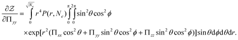
To test this idea we perform the required Legendre transform numerically and compare the results to eqn (45). We show that the result holds for a uniaxial deformation and then assume that it will also be true for biaxial deformations such as shear. Introducing the tensorial field Π conjugate to the end-to-end vector r into the finitely extensible chain partition function gives| |  | (46) |
where P(r, Ne) is the probability of end-to-end vector r for a finitely extensible chain of Ne steps. From here the chain free energy can be defined| |  | (47) |
Differentiating eqn (47) and using eqn (46) leads to| |  | (48) |
where  . Thus Π and W are a conjugate pair and the free energy can be expressed as a function of W by a Legendre transform. The transformed free energy, Fel, can be written as
| |  | (49) |
We will perform this transform numerically for a uniaxial deformation, which W is diagonal and Wyy = Wzz. The final part implies that Πyy = Πzz so we must numerically find the solution of the following coupled system of non-linear equations
| |  | (50) |
| |  | (51) |
to obtain Π
xx and Π
yy from a given
Wxx and
Wyy. We first seek an expression for

. Switching the integral in
eqn (47) into spherical polar co-ordinates, with the axis in the
x-direction gives
| |  | (52) |
Using Π
yy = Π
zz significantly simplifies the exponential and allows the integral over
ϕ to be performed
| |  | (53) |
where the substitution
u = cos
θ has been made. The inner integral can now be performed.
| |  | (54) |
which uses the imaginary error function

, where
D(
x) is Dawson's integral.
39 This leaves a one dimensional integral over
r which can be evaluated numerically. Differentiation of
eqn (54) leads to
| |  | (55) |
which can be evaluated numerically, to give
Wxx since
| |  | (56) |
The differentiation required to produce
Wyy (
eqn (51)) must be performed before the Π
xx = Π
yy result is used. Therefore differentiating
eqn (52) gives
| |  | (57) |
Similarly to above, using Π
yy = Π
zz, performing the integral over
ϕ and substituting
u = cos
θ gives
| |  | (58) |
Again, despite appearances, the integral over
u can be performed to give
| |  | (59) |
In order to evaluate the integrals for
Z and ∂
Z/∂Π
xx and ∂
Z/∂Π
yy we require the probability distribution for a finitely extensible chain
P(
r,
Ne).
Ref. 40 gives this as
| |  | (60) |
where we use Cohen's approximation to the inverse Langevin function

(
eqn (4)) and
A is a normalisation constant whose value is not needed since it merely adds a constant to the free energy. To perform the Legendre transform,
eqn (50) and
(51) are solved numerically using Broyden's method
41 with numerical evaluations of
eqn (54),
(55) and
(59). This provides Π
xx and Π
yy corresponding to a prescribed

and

pair, which can then be used to calculate
Fel with
eqn (49). The numerical results shown in
Fig. 11 were generated by incrementally increasing

, using the previous value of Π
xx and Π
yy to provide a good initial guess for the subsequent calculation. Our results depend only on

not the individual values of

and

.
 |
| | Fig. 11 Comparison between numerical computations of the free energy of a uniaxially deformed finitely extensible chain of constrained average end-to-end vector, with Ne = 100, and the modified Cohen formula (eqn (45)). Also shown is the exact result for Gaussian chains.38 | |
A.2 Monomer orientation.
Similarly, we expect that the distribution of monomer orientations, w(θ), can be approximated by modifying the expression for w(θ)12 with a direct constraint on r. That is, we expect to accurately approximate the monomer orientation distribution for a chain with a constrained average end-to-end vector, f by| |  | (61) |
where  is the inverse Langevin function and θ is the angle with the principle axis of f. To check this we numerically calculate the true values of w(θ) by extending the methods above and compare this to eqn (61). We begin by constraining the partition function so that one of the monomers uj has vector w (with |w| = 1|)
| |  | (62) |
where W0(u) = δ(|u| − 1)/4π is the probability distribution of a freely rotating monomer.38 Carrying out the integral over uj and substituting r′ = r − w gives| |  | (63) |
We switch to spherical polar co-ordinates along the x-axis. However, because of the uniaxial symmetry of Π we can choose the azimuthal angle ϕ so that ϕw = 0. In this co-ordinate system  and
and| | 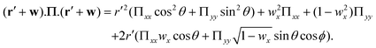 | (64) |
Substituting in eqn (64) gives| |  | (65) |
Carrying out the integral over ϕ and substituting u = cosθ gives| |  | (66) |
where I0 is the modified Bessel function of the first kind.39 The probability of a monomer making an angle θ with the x-axis is given by| |  | (67) |
where the factor of 2π arises by integrating eqn (66) over all possible azimuthal angles of wx. For a given  and
and  pair, the corresponding Πxx and Πyy are already known from the Legendre transform and this allows eqn (66) to be evaluated by numerical computation of the remaining double integral, leading to w(θ). Eqn (61) agrees closely with numerical evaluations, as expected.
Acknowledgements
We acknowledge the EPSRC for funding through the Micro Polymer Processing 2 grant (GR/T11807/01). We thank the members of the Micro Polymer Processing 2 project for useful discussions, especially Luigi Balzano, Rudi Steenbakkers, Gerrit Peters, Oleksandr Mykhaylyk, Tony Ryan and Tom McLeish. RSG acknowledges a travel award from the Royal Society.
References
-
A. Keller and H. Kolnaar, in Processing of Polymers, ed. H. Meijer, Wiley-VCH, Weinheim, 1997, vol. 18, p. 189 Search PubMed.
- I. Coccorullo, R. Pantani and G. Titomanlio, Macromolecules, 2008, 41(23), 9214–9223 CrossRef CAS.
- S. Kimata, T. Sakurai, Y. Nozue, T. Kasahara, N. Yamaguchi, T. Karino, M. Shibayama and J. A. Kornfield, Science, 2007, 316, 1014–1017 CrossRef CAS.
- B. S. Hsiao, L. Yang, R. H. Somani, C. A. Avila-Orta and L. Zhu, Phys. Rev. Lett., 2005, 94, 117802 CrossRef.
- L. Balzano, N. Kukalyekar, S. Rastogi, G. W. M. Peters and J. C. Chadwick, Phys. Rev. Lett., 2008, 100, 048302 CrossRef.
- M. Seki, D. W. Thurman, J. P. Oberhauser and J. A. Kornfield, Macromolecules, 2002, 35, 2583–2594 CrossRef CAS.
- E. L. Heeley, C. M. Fernyhough, R. S. Graham, P. D. Olmsted, N. J. Inkson, J. Embery, D. J. Groves, T. C. B. McLeish, A. C. Morgovan, F. Meneau, W. Bras and A. J. Ryan, Macromolecules, 2006, 39(15), 5058–5071 CrossRef CAS.
- O. O. Mykhaylyk, P. Chambon, R. S. Graham, J. P. A. Fairclough, P. D. Olmsted and A. J. Ryan, Macromolecules, 2008, 41(6), 1901–1904 CrossRef CAS.
- H. Zuidema, G. W. M. Peters and H. E. H. Meijer, Macromol. Theory Simul., 2001, 10, 447–460 CrossRef CAS.
- S. Coppola, N. Grizzuti and P. L. Maffettone, Macromolecules, 2001, 34, 5030–5036 CrossRef CAS.
- R. Zheng and P. Kennedy, J. Rheol., 2004, 48(4), 823–842 CrossRef CAS.
-
L. Jarecki, in Progress in Understanding of Polymer Crystallization, ed. G. Reiter and G. R. Strobl, Springer, Berlin, 2007, vol. 714 of Lecture Notes in Physics, pp. 65–86 Search PubMed.
- J. van Meerveld, M. Hütter and G. Peters, J. Non-Newtonian Fluid Mech., 2007, 150, 177–196.
- N. Waheed, M. J. Ko and G. C. Rutledge, Polymer, 2005, 46, 8689–8702 CAS.
- M. J. Ko, N. Waheed, M. S. Lavine and G. C. Rutledge, J. Chem. Phys., 2004, 121, 2823–2832 CrossRef CAS.
- W. Hu, D. Frenkel and V. Mathot, Macromolecules, 2002, 35, 7172–7174 CrossRef CAS.
- W. Hu and D. Frenkel, Adv. Polym. Sci., 2005, 191, 1–35 CAS.
- J. Zhang and M. Muthukumar, J. Chem. Phys., 2007, 126, 234904 CrossRef.
- I. Dukovski and M. Muthukumar, J. Chem. Phys., 2003, 118, 6648–6655 CrossRef CAS.
- D. Auhl, J. Ramirez, A. E. Likhtman, P. Chambon and C. Fernyhough, J. Rheol., 2008, 52(3), 801 CrossRef CAS.
- J. Bent, L. R. Hutchings, R. W. Richards, T. Gough, R. Spares, P. D. Coates, I. Grillo, O. G. Harlen, D. J. Read, R. S. Graham, A. E. Likhtman, D. J. Groves, T. M. Nicholson and T. C. B. McLeish, Science, 2003, 301, 1691–1695 CrossRef CAS.
- J. Lukkien, J. Segers, P. Hilbers, R. Gelten and A. Jansen, Phys. Rev. E, 1998, 58, 2598–2610 Search PubMed.
- D. T. Gillespie, J. Phys. Chem., 1977, 81(25), 2340–2361 CrossRef CAS.
- J. P. K. Doye and D. Frenkel, Phys. Rev. Lett., 1998, 81, 2160–2163 CrossRef CAS.
- R. S. Graham, A. E. Likhtman, T. C. B. McLeish and S. T. Milner, J. Rheol., 2003, 47(5), 1171–1200 CrossRef CAS.
- M. W. Collis, A. K. Lele, M. R. Mackley, R. S. Graham, D. J. Groves, A. E. Likhtman, T. M. Nicholson, O. G. Harlen, T. C. B. McLeish, L. R. Hutchings, C. M. Fernyhough and R. N. Young, J. Rheol., 2005, 49, 501–522 CrossRef CAS.
- R. S. Graham and T. C. B. McLeish, J. Non-Newtonian Fluid Mech., 2008, 150(1), 11–18 CrossRef CAS.
- A. Blanchard, R. S. Graham, M. Heinrich, W. Pyckhout-Hintzen, D. Richter, A. E. Likhtman, T. C. B. McLeish, D. J. Read, E. Straube and J. Kohlbrecher, Phys. Rev. Lett., 2005, 95, 166001 CrossRef CAS.
- R. S. Graham, J. Bent, L. R. Hutchings, R. W. Richards, D. J. Groves, J. Embery, T. M. Nicholson, T. C. B. McLeish, A. E. Likhtman, O. G. Harlen, D. J. Read, T. Gough, R. Spares, P. D. Coates and I. Grillo, Macromolecules, 2006, 39(7), 2700–2709 CrossRef CAS.
- R. S. Graham, J. Bent, N. Clarke, L. R. Hutchings, R. W. Richards, T. Gough, D. M. Hoyle, O. G. Harlen, I. Grillo, D. Auhl and T. C. B. McLeish, Soft Matter, 2009, 5, 2383–2389 RSC.
- A. Tezel, L. G. Leal and T. C. B. McLeish, Macromolecules, 2005, 38, 1451–1455 CrossRef CAS.
- A. K. Tezel, J. P. Oberhauser, R. S. Graham, K. Jagannathan, T. C. B. McLeish and L. G. Leal, J. Rheol., 2009, in press Search PubMed.
- A. Cohen, Rheol. Acta, 1991, 30, 270 CrossRef CAS.
- L. G. Leal and E. J. Hinch, J. Fluid Mech., 1972, 55, 745 CrossRef.
- G. B. Jeffery, Proc. R. Soc. London, Ser. A, 1922, 102, 161–179 CrossRef.
- L. G. Leal and E. J. Hinch, J. Fluid Mech., 1971, 46(27), 685–703 CrossRef.
- A. E. Likhtman and T. C. B. McLeish, Macromolecules, 2002, 35(16), 6332–6343 CrossRef CAS.
- P. D. Olmsted and S. T. Milner, Macromolecules, 1994, 27, 6648–6660 CrossRef CAS.
-
M. Abramowitz and I. A. Stegun, Handbook of Mathematical Functions, Dover Publications, 1965 Search PubMed.
-
L. R. G. Treloar, The Physics of Rubber Elasticity, Oxford University Press, Oxford, 1975 Search PubMed.
-
W. H. Press, B. P. Flannery, S. A. Teukolsky, and W. T. Vetterling, Numerical Recipes in C: The Art of Scientific Computing, Cambridge University Press, Cambridge, 1992 Search PubMed.
|
| This journal is © The Royal Society of Chemistry 2010 |
Click here to see how this site uses Cookies. View our privacy policy here.