Smart molecules at work—mimicking advanced logic operations
Joakim
Andréasson
*a and
Uwe
Pischel
*b
aDepartment of Chemical and Biological Engineering, Physical Chemistry, Chalmers University of Technology, SE-412 96 Göteborg, Sweden. E-mail: a-son@chalmers.se; Fax: +46-31 772 38 58; Tel: +46-31 772 28 38
bFaculty of Experimental Sciences, Department of Chemical Engineering, Physical Chemistry, and Organic Chemistry, University of Huelva, Campus de El Carmen s/n, E-21071 Huelva, Spain. E-mail: uwe.pischel@diq.uhu.es; Fax: +34-959 99 83; Tel: +34-959 99 82
First published on 16th October 2009
Abstract
Molecular logic is an interdisciplinary research field, which has captured worldwide interest. This tutorial review gives a brief introduction into molecular logic and Boolean algebra. This serves as the basis for a discussion of the state-of-the-art and future challenges in the field. Representative examples from the most recent literature including adders/subtractors, multiplexers/demultiplexers, encoders/decoders, and sequential logic devices (keypad locks) are highlighted. Other horizons, such as the utility of molecular logic in bio-related applications, are discussed as well.
 Uwe Pischel and Joakim Andréasson | Joakim Andréasson (right, born 1973) obtained his PhD degree from Chalmers University of Technology in 2002. After a two-year postdoctoral stay at Arizona State University he returned to Chalmers to start up his own research laboratory. He was appointed Assistant Professor in 2006 and Associate Professor in 2008. His research is focusing on photochromic molecules and their potential application in the fields of molecular logic devices and light-activated anticancer drugs. Uwe Pischel (left, born 1973) studied Chemistry at the Technical University Dresden and Humboldt University Berlin. In 2001 he obtained his PhD degree from the University of Basel, Switzerland. After a short postdoctoral stay at the Polytechnical University of Valencia (2002), Spain, he started his independent career, holding presently a tenure-track Ramón y Cajal position at the University of Huelva. His major research interests include fluorescent molecular switches for the purpose of logic decisions and sensing as well as supramolecular (photo)chemistry with macrocyclic hosts. Both enjoy sports (football, tennis), cooking, and a good glass of red wine. |
Molecular logic
Logic [logikos (λoγικóς), greek = possessed of reason] is surrounding us steadily, for example in verbal communication or when we try to find likely explanations for at first glance unusual or odd situations. Who of us has not already used the phrase: “Let’s be logical.”? We know several forms and application fields of logic, such as philosophical logic or mathematical logic. While these are doubtlessly of high importance, they might not enter in our everyday routines as does logics at the heart of modern information technology and computer science. In our modern and information-based society, computers are for many people an almost indispensable tool to communicate, share information or process data. These operations require computing, with the concept of logic being in the focal point. For this purpose information is coded numerically in form of bits, i.e., binary digits (digita, latin = fingers). That means that a bit can be presented by one of two different values, either 0 or 1. The analog values linked to 0 and 1 are continuous; therefore a threshold limit is defined. In positive logic convention any continuous value above the threshold is considered a 1 and every other as 0. Negative logic convention defines this assignment exactly in the opposite way.In a conventional computer, based on silicon-circuitry, electrical signals are used as in- and outputs. However, the general nature of a bit allows in principle any physical system and related signal, which is able to produce one of two clearly distinguished states, to be used. Applying the laws of Boolean algebra, this supposition opens the door to use molecular entities for the purpose of mimicking the function of logic gates, which constitute the basis of digital information processing. It was the pioneering work of de Silva and co-workers from Queen’s University Belfast, which started the field of molecular logic in 1993.1 As we will show in this tutorial review, clever approaches are still coming up and seem to lead the field to new challenges and approaches. It may be debatable, whether the herein described systems will mount one day in the creation of a molecular computer. However, one does not have to think in such speculative manners to identify ready-to-use implications of molecular logic. The close relation between logic and switching paves in principle the way for applications in multi-parameter sensing,2 encoding of micro-objects such as resin-pearls with applications for combinatorial chemistry,3 and drug release/activity control by means of Boolean operations,4,5 just to name a few examples. Some of these points will be covered in this tutorial review.
It should be noted here, that the use of molecules for mimicking operations common to silicon circuitry has been considered in two related but conceptually different fields: molecular electronics and molecular switching with chemical, photonic or electrochemical inputs and outputs. Molecular electronics focuses principally on the realisation of current-driven functions (transistors, rectifiers, single molecule wires, etc.), involving molecule–metal heterojunctions. In 1988, Aviram suggested the use of “molecules for memory, logic and amplification” in the context of molecular electronics.6 These efforts have been intensified since then and the fruits of this labour have been reviewed in several comprehensive reports.7–9 However, in our discussion we will focus on molecular switches, which show distinct signalling output behaviour as a function of chemical or photonic inputs.
Molecular switches and their basic mechanisms
As briefly mentioned above, molecular switching and logic are two tightly interwoven concepts. In order to illustrate this, it is instructive to discuss one of the simplest examples of a logic operation: the YES function, also known as IDENTITY function. Among the various molecular architectures, which one could imagine for this purpose, systems which show optical output signals enjoy strong preference. This is mainly motivated by the ease with which changes in the absorption spectrum (i.e., colour changes) or alterations of fluorescence properties (change of intensity or band shifts) can be detected and influenced by a quite small but extremely versatile toolbox of excited state processes. These include most commonly photoinduced electron transfer (PET) and internal charge transfer (ICT), electronic energy transfer (EET), proton transfer (PT), and photochromic processes (PC). As will be shown below for some representative examples, photophysical and -chemical engineering is a powerful approach for the tailored design of molecular logic systems.Returning to the YES logic operation, its translation to the scenario of fluorescence switching is quite intuitive: considering positive logic convention, the presence of an input (e.g., a chemical species above the threshold concentration; coded as binary 1) should result in an emission output above a pre-defined threshold level (binary 1). On the other hand, input values below the threshold level (binary 0) yield the observation of low fluorescence (binary 0). Thus, the binary value of the input information is conserved in the fluorescence output, i.e., a YES operation is demonstrated. In terms of molecular design, such a comparably simple situation can be implemented with fluorophore–spacer–receptor conjugates, where the spacer decouples a PET-active fluorescent signalling unit from an electron-donating receptor part. As a precondition, the free receptor should be redox-active and cause PET-induced fluorescence quenching. Upon chemical input recognition and blocking of PET by lowering the electron donor capability of the receptor, the quenching efficiency is diminished. This is accompanied by appearance of increased fluorophore emission as output signal. Classical molecular systems, which integrate such behaviour are fluorophores linked to amines, crown ethers or polyammonium receptors, which can interact with protons, metal cations, and anions, respectively. Scheme 1 shows a small collection of such molecular architectures (compounds 1–7). In this naturally very incomplete set of structures, we have concentrated on anthracene as a common signalling unit, because this fluorophore has enjoyed quite outstanding preference for the conception of many prototypal (and nowadays classical) molecular photoionic switches.10
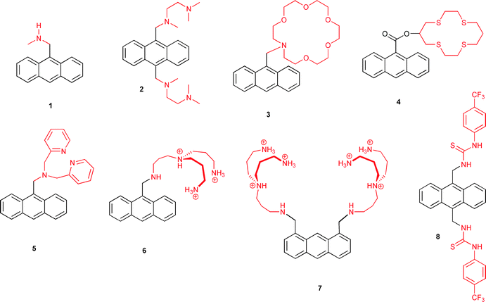 | ||
| Scheme 1 Fluorescent molecular switches based on anthracene chromophores. | ||
Noteworthy, and also quite intuitively, the molecular logic NOT operation requires enhanced PET fluorescence quenching upon recognition of a chemical input by the receptor. This condition is for instance fulfilled by conjugates containing a urea-based receptor (compound 8 in Scheme 1) for basic anions such as fluoride or acetate. The anion binding leads to increased electron density of the receptor, which triggers PET-induced fluorescence quenching.11
The first example of a molecular logic gate, described by de Silva in 1993, mimics an AND function.1 Such behaviour can be understood as the combination of two YES receptors (blocking of PET upon input recognition), which influence in parallel the fluorophore output. In detail, the molecular system 9, designed for this purpose, is composed of an anthracene chromophore linked to two receptor units (cf. Scheme 2). The latter can be addressed specifically by protons and sodium ions in an orthogonal manner, i.e., the chemical inputs only intercept with the corresponding receptor. Both receptor units, in their unoccupied state, give rise to PET, which quenches efficiently the blue fluorescence of the anthracene. The electron donor properties of both electron donors, i.e., amine and dialkoxybenzene, can be influenced by protonation of the amine (receptor1) or sodium ion complexation by the benzo-15-crown-5 (receptor2). However, only when both receptors are occupied simultaneously, all possible PET pathways are blocked efficiently and consequently the brightest fluorescence output of the system is detected. In other words, protons and sodium ions (both binary 1) are needed to obtain strong fluorescence emission (binary 1). On the other hand, blocking of PET by occupation of only one receptor (one input set to binary 0, the other to binary 1) has just a minor effect on the initially (both inputs in the binary 0 state) low fluorescence output (binary 0), because the receptor left unoccupied is still is able to act as efficient electron donor, inducing PET fluorescence quenching. The resulting overall logic operation is AND.
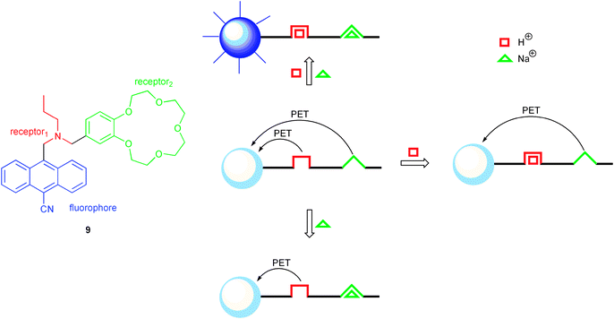 | ||
| Scheme 2 First molecular logic gate (9), mimicking an AND operation, and its photomechanistic working principle. | ||
Since this early report, the two-input AND logic operation has been mimicked by switching PET processes with other systems, based on a comparable molecular design. Further advance was made, with the conceptually related receptor1–spacer1–fluorophore–spacer2–receptor2–spacer3–receptor3 system 10 (Scheme 3), introduced by de Silva and co-workers.2 This molecule delivers the highest fluorescence output, when all three receptors (receptor1 to receptor3, Scheme 3) are occupied with their respective inputs, i.e., sodium ions, protons and zinc ions. The particular value of this arrangement lies in the translation of a complex analytical situation into a single optical output signal. This approach might indeed lead to a “lab-on-a-molecule” with interesting future implications for multi-parameter sensing.
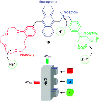 | ||
| Scheme 3 Three-input molecular logic AND gate. | ||
The above introduced molecular systems for mimicking YES and AND logic functions serve herein as illustrative examples to emphasise the relationship between molecular switching and logics. Many more molecular systems were reported for the purpose of mimicking in principle all logic gates, which are nowadays used for silicon circuitry in conventional computing. However, it is not the objective of this tutorial review to summarise all these examples, because a series of excellent and recent reviews on this topic is available in the literature.12–14
The commodity of using PET fluorescence switching is based on the rather straightforward prediction of redox activity trends of receptors in their free and occupied states. This statement applies in a similar way for the control of ICT fluorescence. Some of the most popular examples use fluorophores modified with amino electron donor groups integrated in conjugated π-systems. Such systems have been introduced for the realisation of a series of reconfigurable Boolean logic gates and make also part of more complex logic circuits such as half-adders and half-subtractors (vide infra). For example, McClenaghan and de Silva discussed in a quite comprehensive work a series of ICT fluorophores (11, Scheme 4(a)), whose global fluorescence behaviour lead to multiple logic operations, including one-input YES, NOT and two-input INHIBIT (INH), XOR and NOR logic gates.15 Another example, which combines ICT and PET receptors, was reported by Akkaya and co-workers (Scheme 4(b)).16 Protonation of the N,N-dimethylamino group leads to disturbance of the ICT state, which is accompanied by typical blue-shifts of the fluorescence spectrum. Alkoxide as base input generates a phenolate ion, which yields activation of PET fluorescence quenching. The simultaneous presence of both antagonistic inputs (acid and base) results in chemical neutralisation, leading to the same situation such as in the absence of inputs. The overall switching behaviour of 12 can be interpreted as a combination of INH and XOR logic gates, which mimics the function of a half-subtractor. As a general observation, the use of molecules which show changes of their optical properties (absorption, fluorescence) upon changes of pH has been a preferential choice of many researchers in the field. Some more of these so-called acidochromic switches will be discussed below, in relation to some of the latest advances in combinational logic, such as the already mentioned adders/subtractors or multiplexers/demultiplexers.
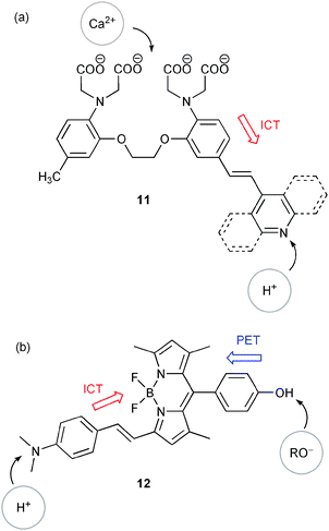 | ||
| Scheme 4 Switches with ICT character as (a) reconfigurable multiple logic gates and (b) half-subtractor. | ||
Alternatively, ICT chromophores, which are based on direct conjugative substitution of an aromatic chromophore with electron-donating amino groups, have been used for switching purposes as well. To illustrate this, we limit ourselves to a very recent example, which is also meant to link the field of molecular fluorescence switching with truly supramolecular interactions based on host–guest complexes (Scheme 5). Compound 13, a carbazole derivative with amino substitution in 3-position, was used by Nau and co-workers to form host–guest complexes with cucurbit[6]uril (CB6) via efficient complexation of the 1,4-diaminobutane-related anchor.17 The host–guest phenomena are accompanied by host-assisted protonation of the 3-amino group through shifts of involved acid–base equilibria. In essence, complex formation with CB6 promotes protonation at pH values, at which free 13 is not affected. Thus, it is possible to change fluorescence through host addition at constant pH from red-shifted ICT-related emission (458 nm) to locally-excited state emission (375 nm) for the protonated form. The mentioned examples demonstrate that ICT systems enable the observation of several optical output channels. This opens interesting possibilities for the design of complex molecular logic operations (vide infra).
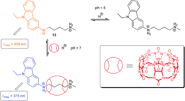 | ||
| Scheme 5 Fluorescence switching through host-assisted guest protonation. | ||
Another mechanism, which has been widely used for the conception of molecular switches, is electronic energy transfer (EET). Given that sufficient spectral overlap between the energy donor emission and acceptor absorption spectrum is observed, EET offers similar commodities such as PET and ICT for straightforward photophysical engineering of molecular switch performance. Hence, it is no surprise that many examples for EET switches are nowadays known. An early example of an optoelectronic molecular gate switch, albeit not discussed in the framework of binary logic, was reported in 1996 by Lindsey and co-workers.18 Their tetrad 14 is composed of three fluorophores (a BODIPY dye, a Zn-porphyrin and the corresponding free-base porphyrin) and a redox-active Mg-porphyrin (Scheme 6). Downhill EET involving the three fluorophores converts the optical input of the BODIPY dye into an emission output of the free-base porphyrin. The excited state level of the Mg-porphyrin is too high-lying to interfere in the EET cascade. However, oxidation with Fe(ClO4)3 generates the Mg-porphyrin radical cation, which possesses a lower energy state and thereby deactivates the output fluorophore in a non-radiative manner. The result is a reduced fluorescence of the free-base porphyrin. The system can be reset by addition of triethylamine as reducing reagent. Similar results have been obtained for electrochemical switching of the oxidation state of the Mg-porphyrin unit.
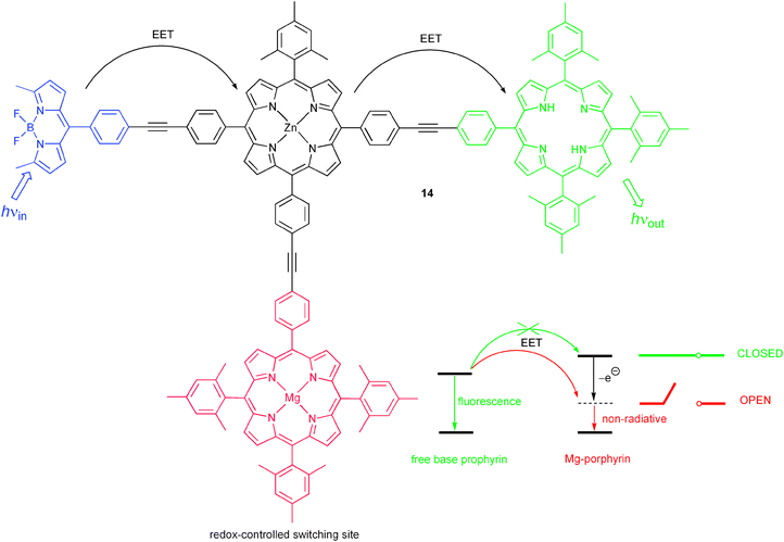 | ||
| Scheme 6 Molecular triad for switching of energy transfer by a redox-controlled energy sink. | ||
Recently, many efforts have concentrated on the design of molecular switches containing photochromic units coupled to fluorophores.19 Photochromic molecules offer by themselves multi-channel optical output possibilities through often dramatic changes in their absorption spectra upon photonic stimulus. On the other hand, it has been demonstrated that changes of electronic and spectral properties, which accompany the photochromic processes, can be favourably used for the modulation of EET, involving a photochrome-appended fluorophore. Scheme 7 shows a representative example reported by Irie and co-workers, which furthermore has been explored as a switch at the single molecule level.20 For the presented dyad 15, fluorescence of the 9,10-bis(phenylethynyl)anthracene derivative shows considerable spectral overlap with the absorption spectrum of the photochromic unit in its closed form. This triggers EET involving the fluorophore as energy donor and the photochrome as acceptor. However, irradiation with visible light changes the photochrome to its open form and consequently its spectral and electronic properties, such that EET becomes much less favourable. Under this circumstance the fluorophore can deliver its unquenched optical output. Examples for molecular logic switches, which incorporate photochromic units, will be given below, including their utility for all-photonic logic operations (vide infra).
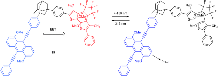 | ||
| Scheme 7 Energy transfer switching modulated by the state of a photochromic dithienylethene unit. | ||
Finally, photoinduced proton transfer has been applied as well for the realisation of molecular switching. One very recent example (Scheme 8) by the groups of Raymo, Constable and Credi, explored the proton-release/capture involved in photochromic processes of a spiropyran/merocyanine system 16.21 The photochrome is operated in presence of an acid–base addressable luminescent Ru(II) complex (17). Depending on the protonation state of the Ru(II) switch, variations of luminescence output signal are obtained and can be interpreted in the framework of molecular logic. The chemical reversibility of all involved processes allows repeated cycling of the system. Of note, the system constitutes an elegant example for chemical communication between molecular switches, which will be briefly discussed below.
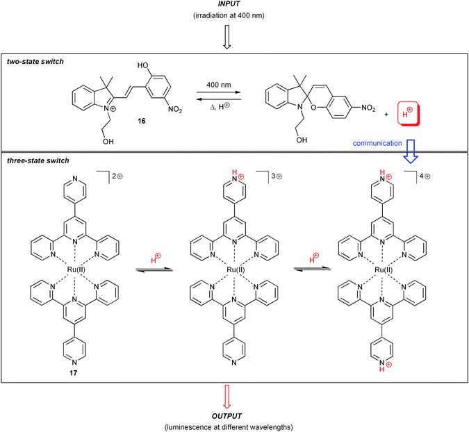 | ||
| Scheme 8 Communication between molecular switches through proton transfer, involving a spiropyran photochrome and a Ru(II) polypyridyl complex with pH-dependent luminescence output. | ||
Silicon circuitry vs. molecular logic
Molecular logic is a quite recent concept and in many respects still in its experimental phase. Thus, at the moment no serious competition with well-established and economy-driven silicon-based computing applies. Many well-implemented issues of the “silicon world” still have to be taught to molecules and alternative chemical approaches have to be validated. For example, in order to achieve functional complexity in conventional electronics, several logic gates are physically integrated through wiring in combinational circuits. Input/output inhomogeneity, characteristic for many molecular systems, limits such straightforward practice. However, chemists came up with the idea of functional integration of complex logic circuits in unimolecular systems. In other words, the global output signal behaviour, depending on input signals, can be interpreted with complex logic patterns without the need to imitate each logic gate by a separate molecular entity.22Many groups have worked on this approach and considerable progress has been made after an early report in 1999,23 where the functional integration of two-input NOR (combination of OR and NOT) and three-input INH (combination of NOT and AND) operations was discussed. Albeit systems are known, where up to 20 (!) logic gates can be functionally integrated in one molecular system,24 it may be foreseen that this approach surely has its limitations in terms of complexity. However, it would certainly be interesting to explore the possibility of linking several multi-performing molecules, i.e., concatenation of molecular switches. Raymo and co-workers have made several promising steps in this direction25 and the above discussed system 16/17 is the most recent on this path.21 This system uses optical inputs and outputs and protons as mediator between both switches 16 and 17. Further, this and other molecular logic devices, which rely on optical inputs and outputs, so-called all-photonic devices, overcome at least formally the input/output inhomogeneity problem. This should in principle allow optical concatenation. However, the multidirectional nature of light makes the directed feeding into another all-photonic switch quite a challenging task at the molecular level. As an alternative to using radiative processes (emission/re-absorption cycles) as concatenation element, non-radiative energy transfer can be directed and may be a path to follow as discussed by Levine, Remacle and Speiser.26 An interesting example for concatenation of enzymatic logic gates has been published recently by the Willner group.27
As mentioned, molecules need to be taught the basic concepts of silicon-based circuitry. On the other hand, there exist also concepts, which lend a touch of exclusivity to the molecular variation. The physical integration of logic elements, such as in silicon-based devices, defines the corresponding logic operation in an unchangeable manner. Any attempt for reconfiguration would inevitably require the destruction of the hardware, because wiring would have to be rearranged. On the other hand, molecular “hardware” opens the possibility for reconfiguration of logic functions through flexible changing of input information, re-definition of output signals or flexible setting of initial situations. An early example for logic reconfiguration by variation of monitoring output wavelength was introduced by Akkaya and co-workers.28 They used the DNA binding DAPI dye together with A–T base pairing to demonstrate the flexible implementation of NAND and YES gates. Others have been using variable input sets and/or different initial states to achieve similar logic variability (see for example fluorescein and its moleculator function in the discussion below).29,30 In this regard, optical molecular logic switches are in the pole position, because in most cases a simple change of the optical input/output may lead to a completely different logic operation. This has enabled the parallel functional integration of logic operations, which lead to complex molecular devices (see discussion below of multiplexers/demultiplexers or adders/subtractors).
Another important aspect from the viewpoint of application of molecular logic devices is their reset capability, i.e., the return to the initial situation for the repetition of the operation cycle. For systems, which are stimulated by acid or base inputs (acidochromic switches) this has been demonstrated by taking advantage of neutralisation reactions. The downside of this approach is that chemical waste products accumulate, which might compromise the accurate function of the logic device from a certain number of switching cycles on. A cleaner method to achieve chemical reversibility of the switching is the use of photochromic systems, which can be switched back by light irradiation or thermal reactions. Two very constructive examples for this possibility are the molecular keypad lock and the encoder/decoder reported by the groups of Andréasson and Gust, discussed below in detail.
It has to be emphasised that molecular logic has up to now taken much inspiration from the aim to imitate functions of silicon-circuitry. This is absolutely legitimate, because the main objective is to increase the functional unit density per specific area (bottom-up approach) and not the total re-definition of existing electronic applications. On the other hand, Richard Feynman’s famous statement “There’s plenty of room at the bottom.” is worth citing here to reinforce that new paths also open possibilities for alternatives and maybe unconventional concepts.31 One of those is logical reversibility, which has found recently attention in quantum computing or DNA computing. All 16 Boolean logic operations, which are based on two input vectors, are characterised by logic irreversibility. This means that the same output is repeated for different input combinations. For instance the XOR gate repeats the output value 1 for the input combinations (0,1) and (1,0) and the output value 0 for the input vectors (0,0) and (1,1). In other words, information is lost during the process. For the example of an irreversible XOR gate, it would be sufficient to add a second output in form of a YES gate to distinguish each input vector by exactly one unique output combination, i.e., to achieve a one-to-one mapping of input and output vectors. Pischel, Pérez-Inestrosa, and co-workers have recently realised a molecular system, which imitates such XOR/YES combination, also known as the Feynman gate.32 For this purpose a “cocktail” of PET-active 1 and the ICT fluorophore 18 is applied (Scheme 9). The two independently operating fluorescent molecular switches deliver well-differentiated optical outputs, which can be addressed by proton and anion inputs.
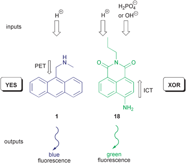 | ||
| Scheme 9 Reversible molecular logic with an anthracene PET switch and an ICT-based 4-aminonaphthalimide. | ||
Sticking to Feynman’s statement, one could go even one step further and challenge the dominance of binary logic. The information content of a signal, i.e., number of distinguishable states, is a key element for potentiality in computing. In principle all efforts in conventional computing with silicon-based microprocessors are focussed on the binary system, i.e., 0 or 1 values. However, by assigning more than two possible states to input and output signals, and thus, implementing multi-valued logic, the density of information can be increased. Taking this as starting point, the Pischel group has reported recently a tri-stable molecular fluorescent switch of the fluorophore1–spacer1–receptor–spacer2–fluorophore2 format.33 In detail, two electronically different 1,8-naphthalimide fluorophores (one of them related to 18) and a proton-accepting and redox-active amino receptor are used (Scheme 10). A delicate fine-tuning of the competition of the PET process between amine and unsubstituted 1,8-naphthalimide (Scheme 10) and, on the other hand, EET between both fluorophores leads to the desired multi-valued logic behaviour. As initial state the protonated form of 19 is set and fluoride ions are applied as degenerate base inputs, corresponding to low (0), medium (1), or high (2) concentrations. Depending on the total fluoride ion concentration (the sum of two degenerate inputs) different levels of deprotonation are reached (Scheme 10), which result in three stable and clearly distinguished fluorescence outputs. These are assigned to 0 (low), 1 (medium) and 2 (high). A careful assignment of the logic operation yields the ternary pendant of a NOR gate.
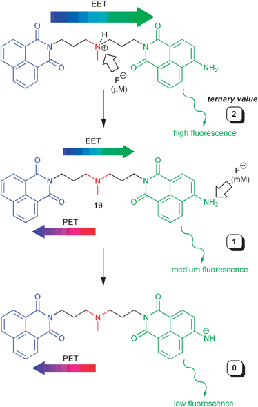 | ||
| Scheme 10 Ternary molecular logic with a naphthalimide-based dyad. | ||
Many of the keywords mentioned above (e.g., reconfiguration, resetting, functional integration, logic decisions for other utility than computing, etc.) can be found in the systems, which we have chosen to discuss below in more detail. They have been selected to illustrate the most recent progress in advanced molecular logic.
Half-adders and half-subtractors
A half-adder (HA) and a half-subtractor (HS) perform addition and subtraction, respectively, of two binary digits. Addition of two binary digits is the most trivial arithmetic operation, and in the 10-base world it corresponds to the following four elementary operations: 0 + 0 = 0, 0 + 1 = 1, 1 + 0 = 1, and 1 + 1 = 2. Translated into binary numbers, the operations are 0 + 0 = 0, 0 + 1 = 1, 1 + 0 = 1, and 1 + 1 = 10. From the latter operation, it is seen that the HA must consist of two binary outputs in addition to the two binary inputs. The inputs represent the two binary digits to be added (augend and addend), and the outputs represent the two least significant bits of the binary sum—the carry digit (C) and the sum digit (S), respectively. The truth table of the HA is shown in Table 1. From this representation it is seen that the HA can be implemented with an XOR gate and an AND gate with shared inputs.

|
The corresponding truth table of the HS is shown in Table 2. The four operations carried out by the HS in 10-base are: 0 − 0 = 0, 1 − 0 = 1, 0 − 1 = −1, and 1 − 1 = 0. This translates into the following operations in the binary system: 0 − 0 = 0, 1 − 0 = 1, 0 − 1 = 11, and 1 − 1 = 0. These results are obtained by letting the borrow digit (B) and the difference digit (D) be represented by the outputs from an INH gate and an XOR gate, respectively.

|
A large number of molecular approaches to the HA and the HS are reported in the literature and several of these have been described in comprehensive reviews.14,34 These systems have developed into more and more complex molecular constructs, and today, the major focus of this line of research is the design and synthesis of systems capable of performing both addition and subtraction—the so-called moleculators (molecular calculators). Noteworthy, it was the pioneering work of Shanzer and co-workers, which introduced the moleculator as such.30 Later on in this tutorial review an elegant example for such advanced device reported by this group will be discussed, enabling rather complex data processing with full-adders and full-subtractors (vide infra).30 However, to start off, we shall first discuss the unimolecular integration of the somewhat simpler HA and HS.35 To illustrate the molecular diversity, which is also a constant driving force of the whole field of molecular logic, we have rather chosen a recent instructive example published by the Liu group, which bases on some ideas originally formulated by Shanzer and co-workers. In detail, a multi-state molecular switch based on 2-phenylimidazo[4,5-f][1,10]phenanthroline (PIPH, 20 in Scheme 11) was reported. The system may exist in four ionisation states (anion: PIP, neutral: PIPH, cation: PIPH2+, and dication: PIPH32+), that are conveniently interconverted using conventional acid/base chemistry and that present characteristic absorption and fluorescence patterns. A HA is implemented by application of degenerate base inputs (3 mM [(Bu)4N]OH) and setting PIPH32+ as initial state. Output emission channels are defined for 423 and 513 nm, which virtually correspond to the fluorescence maxima of PIPH (neutral form) and PIP− (anionic form) states, respectively. Any of these emissions can be interrogated with 335 nm excitation light. The base concentration is chosen sufficiently high, such that addition of the first portion would convert PIPH32+ directly into neutral PIPH, while subsequent addition of a second portion of base would yield PIP− (cf. Scheme 11). This leads straightforward to the observation of strong emission at 423 nm (output O2 = 1, Table 1) for the input strings 10 and 01, while the 513 nm emission channel (output O1, Table 1) is only switched on for the addition of both base portions (input string 11). Only weak emission signals (binary 0) are observed for either channel for the respective other input situations. This defines the 423 nm signal as XOR output and the 513 nm emission as AND output. Hence, according to the general logic definition of the HA function (vide supra) all requirements for such operation are fulfilled by the described system.
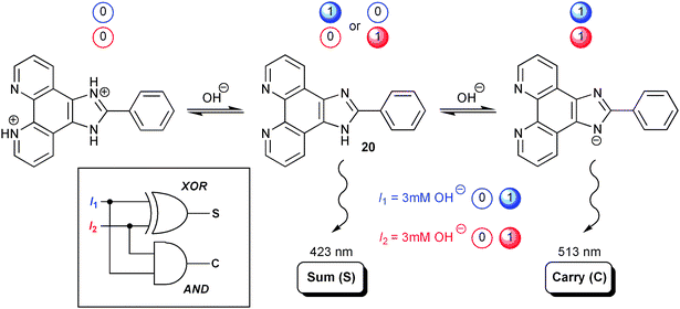 | ||
| Scheme 11 Half-adder based on the phenylimidazophenanthroline 20. Degenerate inputs in form of OH− solutions are used. | ||
Interestingly, the logic performance can be reconfigured for a HS by setting the neutral PIPH form as initial state and monitoring absorbances at 310, 320 and 340 nm as outputs. Because the absorption spectra in this rather narrow spectral range of 30 nm show overlap for the involved ionisation states, the realisation of the HS relies on a comparably less clear-cut assignment of optical properties to a defined chemical species, as discussed above for the HA. However, the intelligent combination of absorbances at these strategically chosen output wavelengths allows the implementation of INH and XOR gates as required for a binary subtraction. PIPH performs simultaneously as two complementary INH gates and one XOR gate when acid and base are used as the two input signals (subtrahend and minuend). With both inputs off, all absorbance values are below the threshold level and all outputs are off. The same applies to the simultaneous presence of both inputs as they annihilate each other by acid–base neutralisation. The addition of only acid yields the dicationic form PIPH32+ with concomitant absorption increase at 310 and 320 nm. On the other hand, sole addition of base results in the PIP− form with its strongest absorption at 320 and 340 nm. Thus, the required XOR gate, providing the difference digit of a HS is implemented by setting the output at 320 nm. The two complementary INH gates with 310 or 340 nm output may each represent the borrow digit. In this style, the order of subtrahend and minuend can be switched simply by switching the monitoring wavelength between 310 and 340 nm. An obvious drawback of the moleculator described above, is that the HA and the HS are operated using different initial states—PIPH32+ and PIPH, respectively. The system must therefore be chemically reconfigured in order to switch between HA- and HS-mode. As a consequence, addition and subtraction cannot be performed in parallel.
Full-adders and full-subtractors
Two HA connected in series together with an OR gate constitute a full-adder (FA) capable of adding three bits, X + Y + Cin, and the corresponding concatenation of n FA elements makes it possible to add two n-bit binary numbers. The FA consists of three inputs and two outputs. Two of the input signals, X and Y, represent the significant bits to be added and the third input, Cin, represents the carry digit from the previous lower significant position.In analogy, the corresponding FS can be implemented by the integration of two HS units. Here, the borrow digit, Bout, is transferred downstream to serve as an input, Bin, together with the higher order bits X and Y allowing for the arithmetic operation X − Y − Bin to be performed. As discussed above, concatenation of several molecular logic units into circuitry of higher complexity is a non-trivial task. Although the abovementioned combination of two HA units to constitute an FA could in principle be realised by integration of two individual HA molecules,26 the most common approach used today is instead to load the complete FA function onto one and the same molecular species through a careful choice of input and output signals (functional integration). After successfully realising an HA/HS moleculator with surprisingly simple acid–base switching between the four different protonation states of fluorescein [F(+1) cation, F(0) neutral, F(−1) anion, and F(−2) dianion],29 the Shanzer group extended their original approach to incorporate the overall function of both an FA and an FS into the same well-known pH indicator.30
As the four forms of fluorescein posses rather well-distinguished UV/vis spectral signatures, optical outputs in form of absorbance or transmittance are defined in a straightforward manner. In brief, at the output wavelength of 447 nm the F(+1) and F(−1) forms have rather strong absorptions, while at 474 nm F(−1) and F(−2) are the main contributors. F(0) is the weakest absorber at these wavelengths. Naturally, the opposite applies to transmittance. Assigning 447 nm as monitoring wavelength to the S and D output and 474 nm to the Cout and Bout, for FA and FS, respectively, leads to the desired logic operations. Degenerate inputs in form of identical portions of OH−, which however are distinguishable to the user (e.g., differently coloured flasks with NaOH solution of same concentration), are used for the FA. On the other hand, the FS is realised with two degenerate OH− inputs and one acid input (HCl). The initial situation of the devices is set to the F(+1) or F(0) state, for FA or FS, respectively.
The in this way realised FA/FS moleculator serves as an elegant example of simplicity-guided approaches toward molecular logic devices. Instead of letting each of the six required input signals be represented by a unique chemical species, the authors introduced degeneracy to allow for the moleculator to be operated using just acid and base as the external stimuli. This drastically lessens the design criteria of the molecular logic platform, as the number of required receptors for input recognition is reduced. Furthermore, the simultaneous addition of acid and base will lead to annihilation of the input signals before even reaching the molecular logic unit, reducing the need for multiple recognition sites even further. On the downside, as follows from defining distinct initial states of FA and FS, the system needs to be chemically reconfigured in order to switch between both operation modes, preventing them to be performed in parallel. This situation is encountered for many multitasking devices, but might be satisfactorily approached by using acid–base neutralisation as a means for easy resetting to any prior state. This cycling and switching of the operation mode could then be repeated for as many cycles as chemical waste products are not challenging the correct functioning of the device. However, depending on the required input concentrations this is very dependent on the chosen molecular design.
Adders constitute the heart of the arithmetic machinery of today’s processors, since all arithmetic functions, including multiplication, division, exponentiation, etc., are implemented by the concatenation of individual adders. Numerical calculations, however, are not the only logic operations needed in data processing. Information transmission and compression are both examples of operations performed by combinational logic circuits, which leads us to data multiplexing and encoding, as discussed below.
Multiplexers and demultiplexers
The function of a multiplexer is to encode the digital state of each of two or more inputs to a single transmission medium, or output, through the use of a selector input, Sel. Thus, a multiplexer can combine several input signals into a single output signal for transmission to a receiver, allowing multiple data streams to be transmitted on a single data line. The receiver must then sort out the entangled data streams from this single signal, directing the data from each of the initial inputs to a separate output. This is the function performed by the demultiplexer, by switching the state of the address input, Ad. The combined action of a 2 : 1 multiplexer and a 1 : 2 demultiplexer is shown in Scheme 12. When Sel is in the off (0) state, the output reports the state of input I1 and ignores the state of input I2. After Sel is switched on (1), the output O reports only the state of I2. The data is then transmitted to reach the demultiplexer. When Ad is set off, then output O1 reports the state of the input I and O2 remains off, whereas when Ad is switched on, O2 reports the state of I. Hence, the function of the combined device is to direct I1 to O1 and I2 to O2 using intermediate data compression.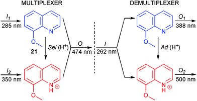 | ||
| Scheme 12 Combined molecular multiplexer/demultiplexer. | ||
Credi and co-workers demonstrated how a plain 8-methoxyquinoline molecule (21 in Scheme 12) in combination with acid/base may be used to constitute a molecular multiplexer/demultiplexer operating in the fluorescent mode.36 Upon addition of acid, 21 is protonated to form 21H+, resulting in substantial spectral shifts in both absorption and emission. In the operation of the multiplexer, I1 and I2 are represented by excitation light at 285 nm and 350 nm, respectively. 285 nm light is mainly absorbed by 21, whereas 350 nm light is exclusively absorbed by 21H+. Acid is employed as the selector input Sel, implying that switching Sel from the off state to the on state will cause protonation of 21 to form 21H+. The output signal is monitored as the fluorescence intensity at 474 nm, where both the protonated and the non-protonated form emit. With Sel in the off state (no H+ added, 21), the output will track the state of I1. After application of Sel (H+ added, 21H+) the output will instead report the state of I2. Thus, the function of the multiplexer is properly described in this setting.
In operation of the demultiplexer, acid is again employed as the address input Ad and excitation at the isosbestic point at 262 nm represents the data input I. O1 is read as the fluorescence intensity at 388 nm where 21 is the stronger emitting fluorophore, whereas O2 is the corresponding emission intensity at 500 nm where 21H+ dominates the fluorescence spectrum. The protonation state of 21 therefore determines to which of the two output channels the data input will be transmitted. Thus, a principle as uncomplicated as acid/base switching of the emission properties of 21 proved to fulfil all requirements for a molecular multiplexer/demultiplexer. However, a drawback for practical applications is that the multiplexer output O emission and the demultiplexer input I absorption are of different wavelengths.
Encoders and decoders
An encoder converts data from one format to another. This is often done to compress information for transmission or storage. An example of an encoder is the single-bit 4 : 2 encoder that converts 0, 1, 2 or 3 in 10-base to the corresponding 2-bit binary number, i.e., 4 bits of data is compressed into 2 bits. The four inputs, I0–13, represent 0 to 3 in 10-base whereas the two outputs, O0 and O1, represent the two least significant bits of a binary number, where O0 is the sum digit and O1 is the carry digit. Following application of any of the four inputs (only one input applied at any given time) the output combination gives the corresponding number in the binary. The truth table of the 4 : 2 encoder is shown in Table 3.

|
A decoder converts the compressed data back to the original form according to the truth table shown in Table 4. The groups of Andréasson and Gust recently reported a molecular photochromic triad (22, Scheme 13) performing as an all-optical 4 : 2 encoder and 2 : 4 decoder.37
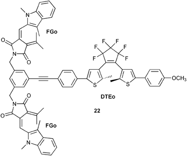 | ||
| Scheme 13 Molecular triad 22, containing three photochromic units. | ||

|
All-photonic devices are operated using light as inputs and outputs, as opposed to the molecular logic devices described so far, where chemical inputs have been used to trigger the molecular responses. Photochromes are molecules that can be isomerised between two different isomeric forms using light. Typically, one of the forms absorbs exclusively in the UV region. Upon UV exposure, this form is isomerised to a visible-light absorbing species, and the reverse reaction is triggered by visible light. Thus, the absorption in the visible region can be described in terms of 0 or 1, respectively, for the two forms. From this trivial example it is obvious that photochromes are strong candidates for all-photonic molecular logic devices. Incorporating several different photochromes into one and the same molecular construct allows for absorption and/or emission readout at multiple wavelengths. Moreover, the photophysical interactions between the photochromic units, e.g., energy- and electron-transfer reactions, may also be tuned by the isomerisation processes, which is an additional means of controlling the fluorescence intensities.
Encoder/decoder triad 22 shown in one of its isomeric forms in Scheme 13 was designed to utilize all the features mentioned above.37 The triad consists of two identical photochromes from the fulgimide (FG) family and one dithienylethene (DTE) photochrome covalently linked around a benzene core. The open forms, FGo and DTEo, absorb mainly in the UV region. Formation of the closed forms, FGc and DTEc, with strong absorption in the visible is triggered by UV exposure, and the reverse reactions are induced by visible light. When triad 22 functions as an encoder, the initial state is FGo–DTEo (no distinction is made between the two individual FG units). The concrete inputs and outputs are summarised in Table 3 (line 2), and Scheme 14 shows the different input-induced isomerisation reactions.
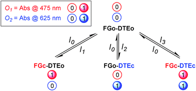 | ||
| Scheme 14 Working principle of the 4 : 2 encoder based on triad 22. | ||
The input wavelengths are chosen so that each photochrome could be selectively isomerised to the closed form by the application of I1 and I2, respectively, while I3 closes both FG and DTE. Hence, all four isomeric states of the triad could be accessed by application of 10–13, and the output wavelengths at 475 and 625 nm reflect the absorbance of the closed forms, FGc and DTEc, respectively. In this way, the absorption in the visible region contains, in encoded form, the information entered into the system by the optical input signals.
FGo–DTEo is also the initial state in operation of the decoder. This means that triad 22 does not have to be chemically reconfigured in the switching between encoder and decoder mode. Moreover, this state is set by exposure to green light, irrespective of the precursor state, i.e., there is a common reset operation that does not depend on the previously applied input combination. This is typically not the case for systems with chemical inputs, where instead each input species must be “neutralised” by a unique chemical species in the reset operation, if resetting is at all possible. The detailed inputs and outputs for the decoder are shown in Table 4 (line 2). Again, all four forms of the triad can be formed by the different input combinations in the truth table, and each isomeric state displays at least one unique spectral feature. These features are chosen to constitute the set of output signals, describing the decoder function.
Incorporating the functions of both the encoder and the decoder into a single molecular entity is logically complex. In the function of the decoder, for example, the output signals must be chosen so that only one of the outputs is switched on for each input combination. This means that I0 must counteract the effect of I1, and vice versa. At the same time, applying both I0 and I1 must give rise to a new, unique output. This implies that the molecule has to perform the functions of one NOR gate, two complementary INH gates, and one AND gate that all share the same inputs and initial state.
Keypad locks
Until this point, the molecular systems described have been able to perform the function of so-called combinational logic devices. These are circuits where the states of the output(s) are only determined by the present input combination. In sequential logic, however, the outputs are not only sensitive to the present input combination, but also to the input history, i.e., to the sequence in which the inputs were applied. Hence, a sequential logic circuit is said to have a memory function whereas a combinational one has not. The logic circuit behind the keypad of a bank machine must be of sequential type, as it has to remember the “three key-strokes history” as well as reading the fourth number in the PIN-code before generating the output response, i.e., authorising the user or not. This is the function of a keypad lock. Given the correct input sequence, the output of the keypad lock is switched to the on state, corresponding to the opening of the lock, to the authorisation of the user, or to the initiation of other processes of interest. Shanzer and co-workers realised the first molecular system mimicking the function of a keypad lock,38 and several groups have since then reported other systems where the function is based on sequential addition of the input signals.The groups of Andréasson and Gust reported the first all-photonic molecular keypad lock.39 The molecular triad used for this purpose consists of a central porphyrin covalently linked to two individual photochromes, which are the same as used for 22: one fulgimide (FG) and one dithienylethene (DTE). As described in the encoder/decoder section above, both photochromes may exist in an open form (FGo and DTEo) and a closed form (FGc and DTEc). The triad may thus assume any of four isomeric structures, and it is possible to prepare solutions that are greatly enriched in each of the four isomers by the use of proper combinations of UV and visible light. In operation of the keypad lock, only three isomers are required. The interconversion pathways between these three isomers are shown in Scheme 15. For the keypad lock function discussed below, the porphyrin emission at 650 nm is monitored upon excitation at 470 nm and used as the output signal. The excitation light at 470 nm is mainly absorbed by FGc, when present, as the absorption coefficient for the porphyrin and the other isomeric forms of the photochromes are low or zero at this wavelength. Although FGc is intrinsically fluorescent, the emission is strongly quenched in the triad due to efficient energy transfer to the porphyrin. The sensitised emission from the porphyrin may in turn be quenched by DTEc through an efficient energy transfer mechanism, whereas the open form DTEo cannot quench the porphyrin due to the zero overlap between the porphyrin emission and the absorption of DTEo. Hence, the pre-requisites for strong emission from the porphyrin to be observed is that the FG photochrome must be in the closed form, FGc, to absorb the 470 nm light and act as a sensitizer for the porphyrin, and also that the DTE photochrome must be in the open form, DTEo, not to quench the porphyrin emission. Therefore, FGc–P–DTEo is the only isomeric form where the porphyrin reporter displays strong emission upon excitation of the triad at 470 nm, as schematically depicted in Scheme 15.
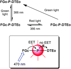 | ||
| Scheme 15 Photochromic processes for the keypad lock based on the FG–P–DTE triad. | ||
When used as a keypad lock, the triad is initially set in the FGo–DTEo form using green light. Input I1 is 366 nm UV light and I2 is red light. The output is porphyrin emission at 650 nm after excitation at 470 nm. As seen in Scheme 15, the only input sequence that isomerizes FGo–DTEo to FGc–DTEo, and thus switches on the output signal, is I1 followed by I2, which accounts for the sequential nature of the input application.
In terms of security, such a system would be of very limited use due to the low number of possible input combinations. This would be overcome by the introduction of an additional input signal, I3, corresponding to the resetting of the triad to the initial FGo–P–DTEo form using green light. As seen in Scheme 15, green light will isomerise the triad to the FGo–P–DTEo form irrespective of the precursor state. Using a ten-key keypad consisting of eight reset keys (I3) together with I1 and I2, would give a total of 100 possible two digit codes where only “1 followed by 2” generates output on, and the lock opens.
Molecular logic with added value outputs
The molecular approach to logic devices is most commonly associated with the mimicry of the functions performed by silicon-based microprocessors. It does not need much imagination to proclaim, that replacing today’s semiconductor components with single molecules (or a small ensemble of molecules) would imply a conceptual change of paradigm when it comes to size reduction, manufacturing process, and increased processing capabilities. Indeed, the appealing topic of molecular computing may be considered something like the holy grail of the field and is therefore often cited in the context of related research activities. However, at the present time it is certainly not easy to predict if the doubtlessly very original approach to molecular logic is the key to the problem. Therefore, one of the most important directions, which molecular logic should follow, is the demonstration of immediate utility. Finding areas of application where there are no pre-potent candidates from the silicon-based world could be of even higher generic value. Merging molecular logic and life sciences may be one path to follow. Besides the fact that biomolecules themselves have attracted a great deal of attention for biocomputing,40 smart and comparably small molecules could function in the broader context as sensors for controlled drug release, etc. In fact, already established pharmaceutical protocols can be described using the Boolean logic language. For example, the enzymatic activation of a pro-drug can be interpreted in terms of a logic YES gate operated with “high enzyme concentration” as the input signal and a “high level of toxicity” as the output signal.Akkaya and co-workers recently showed proof-of-principle for an AND gate-based agent for photodynamic therapy (PDT).5 PDT is typically used as a non-invasive method in the treatment of skin cancer. The method is based on the controlled generation of toxic singlet oxygen upon photo-excitation and subsequent triplet formation of a sensitising chromophore. The generated singlet oxygen will then kill the cells in the skin area exposed to light. Fundamental requirements for the sensitizer chromophore are efficient absorption of the light used for excitation, and a high yield of triplet formation. To increase the generation of singlet oxygen selectively in tumour tissue, it is thus desirable that both the light absorption and the triplet yield of the sensitizer should increase in a cancer cell compared to a healthy cell. Dye 23 was designed for this purpose (Scheme 16). It consists of a benzocrown ether covalently attached to a pyridine appended BODIPY-based chromophore. The charge neutral form shown in Scheme 16 absorbs in the visible region with an absorption maximum at 630 nm. Upon acidification, the pyridine groups are protonated to form the dication with a concomitant red-shift of the absorption maximum to around 660 nm. The crown ether part of dye 23 is a good electron donor. The excited state of BODIPY in dye 23 is therefore rapidly deactivated by PET, which drastically decreases the efficiency of intersystem crossing to the triplet excited state. Upon coordination of Na+ to the crown ether, the electron donating properties are lost which results in an increase in the yield of triplet formation, and thus also more efficient singlet oxygen generation. H+ and Na+, respectively, can thus be used to control the light absorption and the triplet yield of dye 23. The concentrations of these ions are known to be significantly higher in tumour cells compared to normal cells. When used as the AND gate-based PDT agent, dye 23 is excited at 660 nm. At this wavelength the absorption of the neutral, non-protonated form is very low. Addition of H+ will shift the absorption maximum close to the 660 nm excitation wavelength resulting in an increase in the excited state population. However, in the absence of Na+, the triplet yield is still low due to the efficient PET process. Hence, only when the concentrations of both H+ and Na+ are high, the triplet formation is efficient enough to generate singlet oxygen in a concentration above the set threshold level, and the prerequisites for an AND gate are fulfilled.
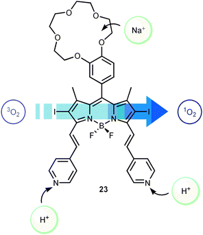 | ||
| Scheme 16 Singlet oxygen generating molecular AND gate based on the BODIPY derivative 23. | ||
Conclusions
Based on the above discussed advanced molecular logic devices, it can be resumed that the field has further developed in the last years. However, for the sake of the credibility of molecular logic much care has to be taken with regard to real and complex molecular computing. Such application might be achievable, but at the moment nothing more than the first fundaments have been laid. Proof-of-principle has been delivered for all basic Boolean logic gates and the most common combinational operations such as the ones discussed herein (adders/subtractors, multiplexers/demultiplexers, encoders/decoders, keypads, etc.). However, from our viewpoint it is also very eminent that important and likely more difficult challenges are waiting ahead. As briefly outlined in this tutorial review, concatenation is one of these barriers. Another milestone would be surely the translation of molecular logic to surfaces and finally solid state devices, not discussed in detail in this tutorial review. If these issues can be resolved, the field will certainly have a promising future. Importantly, logic decisions are not only limited to computing, but have consequences for other areas such as multi-parameter sensing and intelligent drug delivery, which might have even more immediate applications.Acknowledgements
We thank the Spanish Ministry of Science and Innovation (Ramón y Cajal grant and project CTQ2008-06777-C02-02 for U. P.), the Junta de Andalucía (project FQM-3685 for U. P.), the Swedish Research Council (J. A.), the European Research Council (grant ERC FP7/2007-2013 No. 203952 for J. A.), and The Swedish Foundation for International Cooperation in Research and Higher Education (STINT) for generous financial support. Further we would like to thank our colleagues Devens Gust, Gerdenis Kodis, Stephen Straight, and others at Arizona State University, A. Prasanna de Silva (Queens University Belfast), Ezequiel Pérez-Inestrosa (University of Málaga), and Werner M. Nau (Jacobs University Bremen) for helpful discussions and fruitful collaborations on the described research.References
- A. P. de Silva, H. Q. N. Gunaratne and C. P. McCoy, Nature, 1993, 364, 42–44 CrossRef.
- D. C. Magri, G. J. Brown, G. D. McClean and A. P. de Silva, J. Am. Chem. Soc., 2006, 128, 4950–4951 CrossRef CAS.
- A. P. de Silva, M. R. James, B. O. F. McKinney, D. A. Pears and S. M. Weir, Nat. Mater., 2006, 5, 787–790 CrossRef.
- D. M. Kolpashchikov and M. N. Stojanovic, J. Am. Chem. Soc., 2005, 127, 11348–11351 CrossRef CAS.
- S. Ozlem and E. U. Akkaya, J. Am. Chem. Soc., 2009, 131, 48–49 CrossRef CAS.
- A. Aviram, J. Am. Chem. Soc., 1988, 110, 5687–5692 CrossRef CAS.
- J. C. Ellenbogen and J. C. Love, Proc. IEEE, 2000, 88, 386–426 CrossRef CAS.
- J. M. Tour, Acc. Chem. Res., 2000, 33, 791–804 CrossRef CAS.
- R. L. Carroll and C. B. Gorman, Angew. Chem., Int. Ed., 2002, 41, 4378–4400 CrossRef.
- A. P. de Silva, H. Q. N. Gunaratne, T. Gunnlaugsson, A. J. M. Huxley, C. P. McCoy, J. T. Rademacher and T. E. Rice, Chem. Rev., 1997, 97, 1515–1566 CrossRef.
- R. Martínez-Máñez and F. Sancenón, Chem. Rev., 2003, 103, 4419–4476 CrossRef CAS.
- V. Balzani, A. Credi and M. Venturi, ChemPhysChem, 2003, 4, 49–59 CrossRef CAS.
- A. P. de Silva and S. Uchiyama, Nat. Nanotechnol., 2007, 2, 399–410 CrossRef CAS.
- K. Szaciłowski, Chem. Rev., 2008, 108, 3481–3548 CrossRef CAS.
- A. P. de Silva and N. D. McClenaghan, Chem.–Eur. J., 2002, 8, 4935–4945 CrossRef.
- A. Coskun, E. Deniz and E. U. Akkaya, Org. Lett., 2005, 7, 5187–5189 CrossRef CAS.
- A. Praetorius, D. M. Bailey, T. Schwarzlose and W. M. Nau, Org. Lett., 2008, 10, 4089–4092 CrossRef CAS.
- R. W. Wagner, J. S. Lindsey, J. Seth, V. Palaniappan and D. F. Bocian, J. Am. Chem. Soc., 1996, 118, 3996–3997 CrossRef CAS.
- F. M. Raymo and M. Tomasulo, J. Phys. Chem. A, 2005, 109, 7343–7352 CrossRef CAS.
- T. Fukaminato, T. Sasaki, T. Kawai, N. Tamai and M. Irie, J. Am. Chem. Soc., 2004, 126, 14843–14849 CrossRef CAS.
- S. Silvi, E. C. Constable, C. E. Housecroft, J. E. Beves, E. L. Dunphy, M. Tomasulo, F. M. Raymo and A. Credi, Chem.–Eur. J., 2009, 15, 178–185 CrossRef CAS.
- E. Pérez-Inestrosa, J.-M. Montenegro, D. Collado, R. Suau and J. Casado, J. Phys. Chem. C, 2007, 111, 6904–6909 CrossRef CAS.
- A. P. de Silva, I. M. Dixon, H. Q. N. Gunaratne, T. Gunnlaugsson, P. R. S. Maxwell and T. E. Rice, J. Am. Chem. Soc., 1999, 121, 1393–1394 CrossRef CAS.
- K. Szaciłowski, Chem.–Eur. J., 2004, 10, 2520–2528 CrossRef.
- F. M. Raymo and S. Giordani, J. Am. Chem. Soc., 2002, 124, 2004–2007 CrossRef CAS.
- F. Remacle, S. Speiser and R. D. Levine, J. Phys. Chem. B, 2001, 105, 5589–5591 CrossRef CAS.
- T. Niazov, R. Baron, E. Katz, O. Lioubashevski and I. Willner, Proc. Natl. Acad. Sci. U. S. A., 2006, 103, 17160–17163 CrossRef CAS.
- H. T. Baytekin and E. U. Akkaya, Org. Lett., 2000, 2, 1725–1727 CrossRef CAS.
- D. Margulies, G. Melman and A. Shanzer, Nat. Mater., 2005, 4, 768–771 CrossRef CAS.
- D. Margulies, G. Melman and A. Shanzer, J. Am. Chem. Soc., 2006, 128, 4865–4871 CrossRef CAS.
- Title of a talk of Richard P. Feynman at the annual meeting of the American Physical Society at Caltech on 29th December 1959.
- P. Remón, R. Ferreira, J.-M. Montenegro, R. Suau, E. Pérez-Inestrosa and U. Pischel, ChemPhysChem, 2009, 10, 2004–2007 CrossRef CAS.
- R. Ferreira, P. Remón and U. Pischel, J. Phys. Chem. C, 2009, 113, 5805–5811 CrossRef CAS.
- U. Pischel, Angew. Chem., Int. Ed., 2007, 46, 4026–4040 CrossRef CAS.
- Y. Liu, W. Jiang, H.-Y. Zhang and C.-J. Li, J. Phys. Chem. B, 2006, 110, 14231–14235 CrossRef CAS.
- M. Amelia, M. Baroncini and A. Credi, Angew. Chem., Int. Ed., 2008, 47, 6240–6243 CrossRef CAS.
- J. Andréasson, S. D. Straight, T. A. Moore, A. L. Moore and D. Gust, J. Am. Chem. Soc., 2008, 130, 11122–11128 CrossRef CAS.
- D. Margulies, C. E. Felder, G. Melman and A. Shanzer, J. Am. Chem. Soc., 2007, 129, 347–354 CrossRef CAS.
- J. Andréasson, S. D. Straight, T. A. Moore, A. L. Moore and D. Gust, Chem.–Eur. J., 2009, 15, 3936–3939 CrossRef CAS.
- Y. Benenson, Mol. BioSyst., 2009, 5, 675–685 RSC.
| This journal is © The Royal Society of Chemistry 2010 |
