Size-selective separation of micro beads by utilizing secondary flow in a curved rectangular microchannel
Dong Hyun
Yoon
a,
Jin Bong
Ha
a,
Yoen Kyung
Bahk
a,
Takahiro
Arakawa
b,
Shuichi
Shoji
b and
Jeung Sang
Go
*a
aSchool of Mechanical Engineering, Pusan National University, Jangjeon-dong, Geumjeong-Gu, Busan 609-735, South Korea. E-mail: micros@pusan.ac.kr; Fax: +82 51 512 5236; Tel: +82 51 510 3512
bMajor in Nano-science and Nano-engineering, Waseda University, 3-4-1, Ohkubo Shinjuku, Tokyo, 169-8555, Japan
First published on 21st October 2008
Abstract
This paper presents a microscale benefit of a secondary flow obtained in a curved rectangular microchannel, which is generally unfavorable and negligible in conventional fluid flow. We have demonstrated the separation and sorting of micro beads by their size using secondary flow. The physical mechanism occurring in the size-selective separation was explained based on the numerical analysis of the characteristic velocity distribution on the cross-sectional plane normal to the main flow stream. The dynamic trajectories of micro beads of different sizes and materials are visualized and compared for the experimental demonstration. We also discuss the effects of both the shape uniformity of the micro beads and the inlet condition on the size-selective separation.
Introduction
Since the theoretical analysis of flow in a stationary, curved cylindrical pipe was carried out by Dean,1 it is well known that when a fluid flows in a curved pipe with a small radius of curvature, the flow has helical streamlines.2–7 This is called secondary flow, which is a relatively minor flow imposed on the primary flow.8 Secondary flow consists of two symmetric swirling motions being exhibited on both sides of the cross-sectional plane.9This secondary flow can be found in numerous flow situations such as the blade passage in turbomachinery, a bent pipe, aircraft intakes, diffusers, and heat exchangers.10–15 However, they consider the secondary flow as being the loss of momentum and energy.
In this study, the secondary flow is favorably used to separate micro beads by size in the curved rectangular microchannel. Today's microfabrication technology can specifically provide a much smaller radius of curvature for the curved microchannel. This small radius results in increasing the Dean number, so that a strong secondary flow can be induced. We first perform a numerical analysis on the velocity profile of the secondary flow on the cross-sectional plane. The size-selective separation of micro beads of different sizes and materials is visualized.
The working principle size-selective separation
The steady flow of an incompressible viscous fluid containing micro beads of different sizes along the curved rectangular channel of a uniform cross-section is considered. Fig. 1 describes the curved microchannel in the cylindrical coordinate system and the schematic diagram of the velocity distribution that results from the secondary flow. As Dean's works examined, the strength of the secondary flow depends on a dimensionless parameter known as the Dean number, K. It is defined as a function of the Reynolds number, Re, the hydraulic diameter for the rectangular channel, Dh, and the radius of curvature, R, where U denotes the mean velocity in the channel. The radius of curvature denotes the distance from the origin to the center of the channel. The Dean number increases when the radius of curvature decreases and the Reynolds number increases, which allows a stronger secondary flow to be obtained.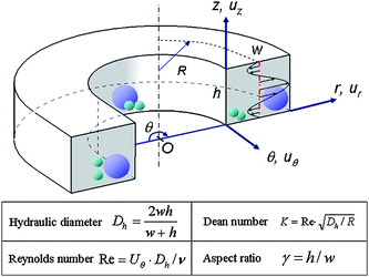 | ||
| Fig. 1 Schematic diagram of the curved microchannel and important design variables for the separation of beads of different sizes. | ||
When the fluid flows along the curved section, the water pressure at the inner wall is slightly greater than that at the outer wall. Thus, the fluid near the center of the channel is pushed outwards due to this pressure gradient and near the top and bottom the wall moves inwards to satisfy the principal of mass conservation. The symmetrically swirling secondary flow is set up on the cross-sectional plane of the microchannel as a result of this.
A numerical analysis of the secondary flow was performed for the various Dean numbers in Fig. 2. The secondary flow was apparent once the Dean number reached about 5. The secondary flow then grew as the Dean number increased. Microchannels with different aspect ratios were also compared. For the same Dean number, a much stronger secondary flow was obtained in the microchannel with a higher aspect ratio. We plotted the velocity profiles for the various Dean numbers on the cross-sectional plane located at θ = 90° of the curved microchannel with an aspect ratio of 1.0, as is shown in Fig. 3. It shows the interesting result that the zero velocities on the plane were always positioned at the same normalized height of 0.27 and 0.72, regardless of the different Dean numbers.
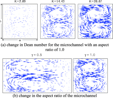 | ||
| Fig. 2 Two dimensional vector fields for various Dean numbers in the curved microchannel and different aspect ratios. (a) Change in Dean number for the microchannel with an aspect ratio of 1.0. (b) Change in the aspect ratio of the microchannel. | ||
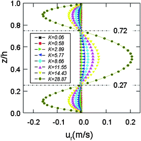 | ||
| Fig. 3 Velocity distributions at θ = 90° and γ = 1 for various Dean numbers. | ||
This characteristic profile of velocity on the cross-sectional plane and the constant positions of zero velocity explain the mechanism of size-selective separation. The travelling micro beads suspended in the water along the curved microchannel are exerted by the fluidic force known as the Stokes force. Its magnitude is proportional to the dynamic viscosity, which is the net fluid velocity distributed on the bead and the bead radius. The direction of movement of these micro beads is in the same direction as the velocity. Therefore, conceptually, a large bead mainly experiences a force from the outward velocity, while a small bead is dominantly forced by the inward velocity, as is depicted in Fig. 4. As a result, the large micro beads move to the outer wall and the small beads move to the inner wall by passing through the curved rectangular microchannel. The opposite movement of the micro beads causes the continuous size-selective separation of beads by means of the secondary flow.
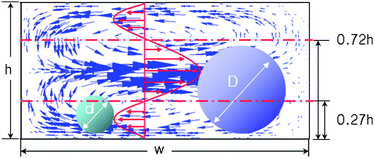 | ||
| Fig. 4 Size-selective separation of micro beads in the direction of the fluidic force exerted by the velocity distribution. | ||
Design of the curved microchannel
Both of the variables of zero velocity and aspect ratio can be used to design the sizes of the microchannel in order to selectively separate the small and large beads. Here, the small bead was considered to be smaller than 27% of the channel height in order to obtain a net velocity in the inward direction, while the maximum diameter of the large bead was obtained by using 72% of the channel height.In the microchannel design, two different glass beads with diameters of 20 µm and 40 µm were considered to be separated. The height of the microchannel was calculated to be 75 µm based on the definition of the small bead. Also, the aspect ratio of 0.5 was taken in order to optically distinguish the separation of the micro beads in the curved microchannel. As a result, the width of the channel was determined to be 150 µm. The minimum radius of curvature of 200 µm was determined by considering the channel width.
Fabrication of the curved microchannel
A high pressure is applied to introduce the situation of a high Dean number in the microchannel. Thus, in order to prevent the delamination and fracture of the bonded dissimilar materials, the curved rectangular microchannel was fabricated by bonding silicon and Pyrex glass instead of using simple polymer machining. First, the 200 µm-thick silicon substrate was etched using the double step deep reactive ion etch. Fig. 5 shows the SEM image of the 75 µm-deep and 150 µm-wide microchannel with the two inlets and two outlets according to the design. The radius of curvature was 200 µm. Then, the 200 µm-thick Pyrex glass (#7740), which was used for optical visualization, was anodically bonded to the etched silicon substrate to form a rectangular microchannel. One inlet was used for introducing beads and the other for controlling inlet flow rate. Two outlets were used for sorting the separated beads by size.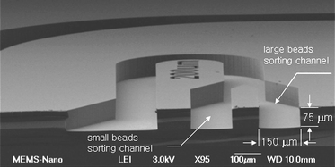 | ||
| Fig. 5 SEM image of the fabricated, curved rectangular microchannel with a radius of curvature of 200 µm. | ||
Visualization of the size-selective separation
The curved rectangular microchannel bonded with transparent glass was placed in a microscope and a high speed CCD camera was installed to visualize the behaviour of the micro beads. This system can record 1000 images per second in the full scale of the CCD sensor. The inlet flow rate was controlled using a syringe pump, while the control inlet was not only designed to control the inlet flow rate but also to push the micro beads to the inner wall. The initial position of the beads can be used as the reference to examine their trajectories. It is also designed that after separation, the beads are sorted to the bifurcated channels according to their size.We examined nickel beads and spherical glass beads of 40 µm diameter. The inlet condition had a Dean number of 28.87. The nickel beadswere 3 times heavier than the glass beads. The sizes of the nickel beads were distributed in the range from 1 µm to 10 µm and their shape was not spherical. The 40 µm glass beads and nickel beads were mixed in the water. The water containing the micro beads was syringe-pumped.
Fig. 6 shows that the nickel beads and glass beads were perfectly separated as expected. The trajectories of all the nickel beads showed an inward movement, while the glass beads moved outwards. This separation became distinct as the Dean number increased. Also, after the separation, the mixed beads were sorted into two different outlet channels according to their size and material, as is shown in Fig. 7.
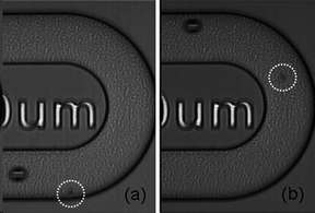 | ||
| Fig. 6 Visualization of size-selective separation for simultaneous size-selective sorting at K = 28.87. | ||
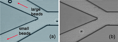 | ||
| Fig. 7 Size-selective sorting of the glass beads and nickel beads in the outlets at K = 28.87. | ||
For the quantitative evaluation, the movement of beads was examined by analyzing the pixels of beads on the images read from the high speed CCD camera. The pixels that contained the streak of the micro bead in each image were marked with a circle in order to display the trajectory of the micro bead movement. Fig. 8 compares the trajectories of the glass bead of 40 µm and the nickel bead of 10 µm in the curved rectangular microchannel. The movement of the micro beads was identically distinguished with successful separation by size.
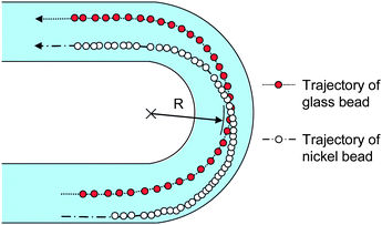 | ||
| Fig. 8 Comparison of the trajectories of the glass and nickel beads at K = 28.87. | ||
Discussions of the size-selective separation
We also compared the 20 µm and 40 µm diameter spherical glass beads. The inlet condition was setup at a Dean number of 14.43. When the beads travelled along the curved microchannel, the 40 µm glass beads showed a radical movement outward and the 20 µm glass beads moved inward. The two different sized micro glass beads were successfully separated.However, as the Dean number increased to 28.87, we found that the small glass beads of 20 µm began to move outwards. It is visualized that this unexpected behavior was resulted from the occurrence of the bead floating in the microchannel. In order to determine the mechanism of the bead float, the velocity field in the direction of the z-axis was obtained numerically. Near the inner wall, the velocity was directed upward, and at the outer wall it showed a downwards direction. In the middle, there is no z-directional flow velocity. Specifically, this upward velocity at the inner wall caused the small glass beads travelling along the inner wall to float. As a result, at the high Dean number flow, this upward velocity became stronger and they were pushed outwards.
To prevent the micro beads from floating, together with using the heavy beads, an alternative is to use flow lamination. In a strong low Reynolds flow regime, three fluid flows are generally laminated. The micro beads suspended in the middle lamination flow may not be influenced by the z-directional flow.
Also, based on the numerical analysis, the downward z-directional flow was obtained along the outerwall in the curved rectangular channel. Thus, if the micro beads are controlled to be positioned in the outerwall, it is also expected to be effective to settle down the micro beads on the bottom surface.
The performance of the size-selective separation using the curved microchannel depends on the specific gravity of the micro beads, size and even shape. There will be a restriction in isolating a specific bead from the fully mixed beads with different sizes, materials, and shape. Specifically, the resolution of size-selectivity seems to be bimodal at this moment. Related with size, it may be possible to end this by putting the curved microchannels with different size and radius of curvature of microchannels in series. In addition, it can also be used to separate the micro polymer beads with a lower specific gravity. The high velocity in the microchannel is required to obtain the secondary flow. By narrowing the microchannel, such as with a nozzle, it is possible to obtain the high velocity locally.
Conclusions
In this work, a new concept of the continuous size-selective separation of mixed micro beads was successfully suggested. The initial vertical position of the micro beads in the microchannel had a distinct effect on the performance of the size-selective separation. Thus, consideration of this is required to introduce the micro beads along a designed location regardless of specific gravity, shape, and the direction of the inlet. The focused stream scheme using lamination flow is a candidate for further study.For a practical use, the resolution of the size-selective separation must be taken into account by comparing the inertia force and the fluidic force to direct the behaviour of the micro beads. The inertia effect is proportional to the cube of the diameter and the fluidic effect is linearly proportional to the diameter. It is expected that the inertia effect is negligible relative to the fluidic effect in the micro scale. However, as the Dean number increases, the experimental results showed that the inertia effect was not negligible. A balance between the inertia effect and the fluidic force must be explained in order to obtain the size-selective resolution of the beads.
By using this separation mechanism, there is the possibility of generating constant micro beads by putting the size-designed curved microchannel in sequence. The various sizes and materials, along with the resolution of the micro beads will be separated size-selectively and linked with biomolecular assemblies in our future works.
Acknowledgements
This work was supported by the Korea Foundation for International Cooperation of Science & Technology (KICOS) through a grant provided by the Korean Ministry of Education, Science & Technology (MEST) in 2007 (No. K20702000013-07E0200-01310).References
- W. R. Dean, Phil. Mag. (7), 1928, 5, 673–695 Search PubMed.
- K. C. Cheng, R. C. Lin and J. W. Ou, J. Fluids Eng., 1976, 3, 41–48.
- S. A. Berger, L. Talbot and L. S. Yao, Annu. Rev. Fluid Mech., 1983, 15, 461–512 CrossRef.
- S. P. Vanka, G. Luo and C. M. Winkler, AIChE J., 2004, 50(10), 2359–2368 CrossRef CAS.
- J. Zhang, B. Zhang and J. Ju, Int. J. Heat and Fluid Flow, 2001, 22, 583–592 Search PubMed.
- J. M. C. van't Westende, et al., Int. Journal of Multiphase Flow, 2007, 33, 67–85 Search PubMed.
- A. Yu. Gelfgat, A. L. Yarin and P. Z. Bar-Yoseph, Phys. Fluids, 2003, 15(2), 330–347 Search PubMed.
- P. Petitjeans, J. L. Aider and J. E. Wesfreid, Exp. in Fluids, 1997, 23, 388–394 Search PubMed.
- K. N. Ghia and J. S. Sokhey, J. Fluids Eng., 1977, 99, 640–648.
- K.-I. Funazaki, S. Nakano, Proceeding of the Third JSME-KSME Fluid Engineering Conference, Japan, 1994, 438–443 Search PubMed.
- J. Moore and R. Y. Adhye, Transactions of the ASME, Journal of Engineering for Gas Turbines and Power, 1985, 107, 961 Search PubMed.
- H. E. Fieldler, Exp. in Fluids, 1997, 23, 262–264 Search PubMed.
- R. K. Sullerey and A. M. Pradeep, J. of Fluid Engineering, 2004, 126(4), 650–657 Search PubMed.
- P. Graves, Ph.D. Thesis, University of Durham, 1985.
- J. Walsh, Ph.D. Thesis, University of Durham, 1987.
| This journal is © The Royal Society of Chemistry 2009 |
