Textural guidance cues for controlling process outgrowth of mammalian neurons†
Jennifer N.
Hanson
b,
Michael J.
Motala
a,
Michael L.
Heien
b,
Martha
Gillette
c,
Jonathan
Sweedler
b and
Ralph G.
Nuzzo
*ab
aDepartment of Chemistry, University of Illinois, Urbana-Champaign, 505 South Mathews Ave., Urbana, IL 61801, USA
bDepartment of Material Science and Engineering, University of Illinois, Urbana-Champaign, 1304 W Green St., Urbana, IL 61801, USA
cDepartment of Cell and Developmental Biology, University of Illinois, Urbana-Champaign, 393 Morrill Hall, MC-119, 505 South Goodwin Ave., Urbana, IL 61801, USA
First published on 21st October 2008
Abstract
We explore textural cues as a mechanism for controlling neuronal process outgrowth in primary cultures of mammalian neurons. The work uses a form of decal transfer lithography to generate arrays of PDMS posts of various dimensions and spacings on glass substrates that are rendered growth-compliant by subsequent treatment with a protein activator. Hippocampal neurons plated on these substrates are used to determine how the posts direct process growth by acting as attachment points or guidance cues. Textural features varying over a large range, even as large as 100 µm in diameter, dramatically affect process growth. Indeed, two growth regimes are observed; at the smaller feature sizes considered, process branching strongly aligns (at right angles) along the post mesh, while neuronal outgrowth on the larger feature sizes elicits process wrapping. The latter behavior most strongly manifests in neurons plated initially at ∼100 cells/mm2, where the cells were able to form networks, while for isolated neurons, the cells exhibit poorer viability and development. Bag cell neurons from Aplysia californica also display regular growth patterns, but in this case are guided by contact avoidance of the posts, a behavior qualitatively different than that of the hippocampal neurons.
Introduction
Creating surfaces with defined topography is a simple way to manipulate the environment that a cell experiences on the micrometer and nanometer scale. As a result, there has been increasing attention given to the study of the impact of these factors on the characteristics of cells maintained in vitro.1–25 More recent work in this area has largely exploited the development of new, more enabling protocols for fabricating substrates that provide attachment points or guidance cues for cellular attachment and growth. Substrates, particularly those presenting more complex forms of three-dimensional texture, are predominantly desirable for many types of studies. The work reported here is addressed to this need and examines responses of primary mammalian neurons to a set of novel design rule structures fabricated by soft lithography.26–29The architectures and design rules that are examined here are ones that are easily accessed by soft lithography or more conventional forms of photolithography.14,15,20,24,30,31 Many of the previously reported studies of cell guidance have used PDMS substrates containing microchannels/grooves, many of which were created by replica molding (a simple technique that allows the fabrication of complex patterns with feature sizes down to the nanometer scale).4,7,19,25 Several previous studies also considered microgrooves/channels fabricated in fused silica or quartz.1–3,5,6,10 Taken together, these studies present a somewhat confusing picture as to the nature and specificities of contact cues as a mechanism for controlling process outgrowth. One of the main conclusions in the majority of past studies using microgrooves/channels is that cells prefer to interact with topography whenever possible, with some lesser affirmation that the design rules that most effectively promote textured outgrowth involve feature sizes that are possibly well below 10 µm.1–12,14–21,24,25
Few studies have considered the behavior of cells on other substrate design form factors, such as the post or pillar arrays considered here. The studies which have, however, examined posts no larger than 2 µm in diameter.11,16 In the present work, we considered a broader range of design rules, ones embracing both small and large feature sizes, (reaching as large as 100 µm in diameter), as cell behavior at this scale with discrete features had not been previously examined. Of the past work, the study that provided the most relevant information to the investigation conducted here was that by Dowell-Mesfinet al.16 who investigated the effects of a pillar device topography (created on a silicon wafer using photolithography) on the development of an approximate 35 cells/mm2 density culture of embryonic hippocampal neurons. Arrays of pillars, fabricated with two different widths (0.5 µm and 2 µm) and various spacings ranging from 1 to 5 µm, were studied and the results compared to growth on smooth silicon surfaces. It was concluded that the 2 µm-wide pillars with the smallest spacing were most important in providing neuron guidance. Above this spacing and dimension range, strong guidance was not evidenced. In contrast, we find here that strong guidance can result from growth of hippocampal neurons on substrates bearing feature sizes that are two orders of magnitude larger than those considered in the earlier study of Dowell-Mesfinet al. In order to determine if these effects depend on the type of neuron, we also investigated Aplysia californica bag cell neurons (BCNs). The BCNs also showed strong guidance on substrates comprised of small pillars with small spacings, but in this case, dictated by contact avoidance of the posts. Finally, we also show that the texture of the substrates strongly impacts how the cell somas attach to the substrate, an effect not previously reported by others.
The substrates used in this study were created using a form of decal transfer lithography32–34 so-called ‘masterless soft lithography’, developed previously.35 With this method, which is schematically represented in Fig. 1, PDMS features of a range of diameters and spacing were transferred to clean glass surfaces. Examples of transferred arrays are given in Fig. 2. The method does not pattern posts, but instead transfers the PDMS in the form of a well defined conical topography, as is highlighted in Fig. 3. The advantage of this system over a microgroove/channel architecture, as we show in the present study, is the potential to direct growth in both two and three-dimensions. This control capacity is design rule sensitive, however, as the bulk of previous studies considered feature height sizes that were too small to fully elicit cell growth in the z-direction. The height of the largest diameter posts considered in this study (50 and 100 µm) was approximately 6 and 14–20 µm (depending on the spacing), respectively. Three-dimensional growth was clearly seen on surfaces bearing features of these sample sizes. The ability to direct cell growth in this third dimension is especially desirable as we believe it will eventually make it possible to create conditions similar to those found in vivo.
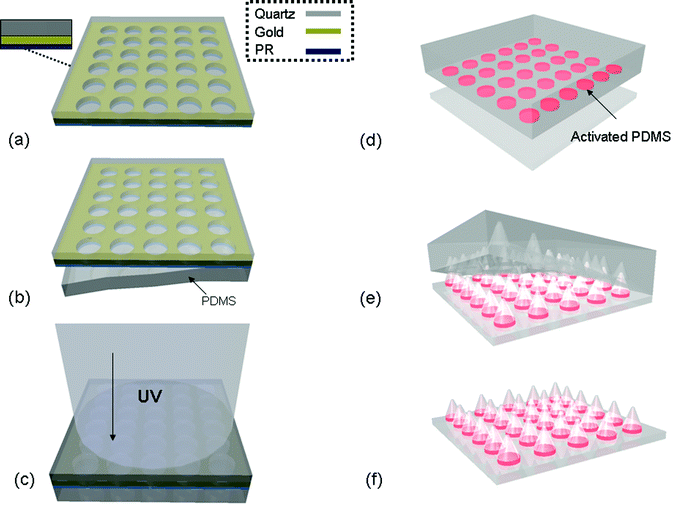 | ||
| Fig. 1 Schematic representing the masterless soft lithography transfer method. (a) Depiction of the UVO photo mask with insert illustrating a cross section of the components of the mask. (b) The patterned side of the UVO photomask is brought into conformal contact with a flat unpatterened PDMS slab and then (c) exposed to UV/Ozone (through the quartz side of the mask) to activate the PDMS in discrete regions. (d) The activated PDMS is then separated from the mask, placed activated side down onto a clean glass substrate, and heated at 70 °C for at least 1 hour. (e) After cooling to room temperature, the bulk PDMS is slowly peeled from the glass surface, creating an array (f) of conical PDMS features on the glass coverslip. | ||
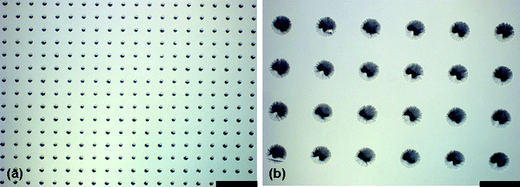 | ||
| Fig. 2 Optical micrographs of PDMS conical features on glass substrates formed using masterless soft lithography. (a) 20 µm diameter with 40 µm spacing (edge to edge) (b) 100 µm diameter with 100 µm spacing. Scale bar is 180 µm. | ||
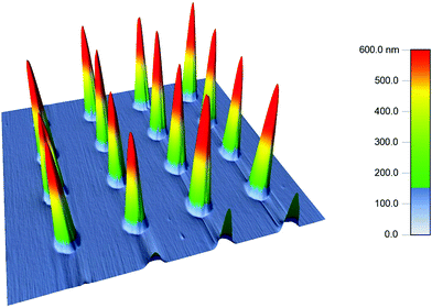 | ||
| Fig. 3 Height profile of 10 µm diameter with 10 µm spacing PDMS conical post array captured using tapping mode AFM. | ||
Both mammalian and non-mammalian animal systems were investigated to determine if the material system and branching characteristics consequently displayed were unique to mammalian neurons. To the best of our knowledge, there is only one other study that considered the growth of non-mammalian neurons on textured substrates, which was that conducted by Merz et al.13 In that study, they created a very specific cell platform for neurons from pedal ganglia of the pond snail Lymnaea stagnalis, a source used for both reasons of their large cell somas (that allowed for ease in manipulation) and their capacity to form strong electrical synapses between neurites. In their study, the cell somas were placed into interconnected ‘pits’ and allowed to navigate their processes through a series of connected microchannels. Here we investigate both mammalian hippocampal neurons, taken from postnatal day two rats, and non-mammalian Aplysianeurons, harvested from mature California sea slugs. The mammalian neurons are more relevant to understanding human health and may aid in the creation of neural biomedical devices. We also included the non-mammalian neurons, as Aplysia are a well-studied model for neuronal outgrowth and repair, and thus links our study to a significant body of prior work.36–46 Consequently, the use of two distinct cell types offers insight into the universality of the material system and the specificity of the conclusions on topographic features.
In the sections that follow, we describe the growth behaviors of hippocampal neurons on substrates bearing discrete, but chemically modified (with poly-lysine) PDMS attachment points. Lateral feature sizes, in the system studied, ranged from 10 to 100 µm, with spacings extending from 10 to 200 µm, edge to edge. At the upper range, these features are significantly larger than those considered in previous cell guidance studies. The behavior of the developing neurons is distinctly tailored in ways that accorded to the feature sizes and spacing presented by a growth-compliant substrate.
Materials and methods
Surface topography
Surface topography was created on glass coverslips using ‘masterless soft lithography’,35 a variant of decal transfer lithography32–34 that was developed previously. A detailed description of this method can be found elsewhere.35 A schematic representation of this method is presented in Fig. 1. Briefly, UVO microreactor masks were first fabricated through a series of standard photolithographic steps, as follows. Quartz slides were cleaned in a piranha solution for at least 30 minutes, rinsed thoroughly with deionized water (Milli-Q, Millipore, Billerica, MA) and dried under flowing nitrogen. A 100 Å adhesion layer of titanium, followed by 1000 Å of gold were evaporated onto the surface of the slides (Temescal FC-1800 electron beam evaporator). The slides were then spin coated with s1805 photoresist (Rohm & Haas Electronic Materials, Philadelphia, PA) at 3000 rpm for 30 s, with a ramping of 500 rpm/sec. The coated slides were pre-baked at 115 °C for 3 minutes and then exposed to UV for 7 seconds (MJB3 Mask Aligner, Suss Microtech, Garching, Germany) through a transparency to define the features. The patterned slides were post-baked for 3 minutes at 115 °C and then developed using MF™-319 developer solution (Rohm & Haas Electronic Materials). After photolithographic patterning, an O2 reactive ion etch (RIE) descum (30 s, 100 W, 20 sccm O2, 50 mTorr, Unaxis, Plasma Therm) was performed. The slides were then placed in a gold etch (gold etch type TFA, Transene Company, Inc., Danvers, MA) for approximately 30 s, rinsed with deionized water and then dried under flowing nitrogen. Photoresist covering the remaining gold was not subsequently removed. In the final structure, the gold acts as a masking element (similar to a photolithography mask) while the photoresist forms the sidewalls of a reusable micro reaction chamber under the gold openings.Patterning using the UVO microreactor masks was carried out by placing the patterned side of the mask on top of an unpatterened PDMS slab and exposing the assembly to UV irradiation (UVOCS; UVOCS Inc., Colmer, PA) through the top of the mask for 5 minutes. The activated face of the PDMS slab was then placed into conformal contact with a glass coverslip, previously cleaned by piranha treatment, rinsed with deionized water and dried with nitrogen. To prevent PDMS delamination, a weight was placed on top of the PDMS. The stack was then heated (glass on the bottom of the stack) for a minimum of one hour at 70 °C (larger feature sizes transferred better with longer cure times). After heating, the weight was removed and the bulk PDMS was then carefully peeled from the substrate, slowly pulling diagonally from one corner, across the coverslip. This procedure creates a pattern transfer of conical PDMS structures on the surface, corresponding to the approximate geometries that were initially present on the UVO microreactor mask. An exact 1:1 transfer of the photomask pattern was not observed; typically the transferred patterns were slightly smaller than the presented mask features (i.e. a 10 µm diameter, 10 µm spacing sample may appear as an array with 8 µm diameter and 12 µm spacing). The patterns generated for this study had a diameter range of 10 to 100 µm, a spacing range (from edge to edge) of 10 to 200 µm, and a height of 1 to approximately 20 µm, depending on post diameter.
Feature height characterization
Atomic force microscopy
Atomic force microscopy (AFM) was used to determine the height and shape of the PDMS conical features. A MFP-3D AFM (Asylum Research, Santa Barbara, CA) system was used in tapping mode, with generic aluminum tips, for this imaging and analysis. The scannable area of the instrument was 90 µm2, so the height of the three largest features could not be properly determined. (See below.) An example of an AFM height profile for the 10 × 10 sample (10 µm diameter with 10 µm spacing) is given in Fig. 3.Profilometry
The height of the three largest feature sizes considered in this study (50 × 100, 100 × 100, and 100 × 200 µm) was determined using a surface profiler (Dektak 3030; Veeco, Woodbury, NY). The heights of all features are summarized in Table 1.| Sample (µm) | Post height (µm) |
|---|---|
| (diameter × spacing) | |
| 10 × 10 | 1.0 ± 0.2 |
| 10 × 15 | 1.4 ± 0.1 |
| 10 × 40 | 0.7 ± 0.1 |
| 15 × 10 | 2.1 ± 0.2 |
| 20 × 10 | 3.4 ± 0.1 |
| 20 × 40 | 2.6 ± 0.5 |
| 50 × 100 | 6.1 ± 0.8 |
| 100 × 100 | 19.0 ± 2.1 |
| 100 × 200 | 13.5 ± 1.5 |
Cell culture of mammalian neurons (P2 Long Evans rats)
The cell plating procedure used is one modified47 from the work done by Brewer48 on adult rat hippocampal neurons. Prior to culture, patterned and PDMS-coated samples were sterilized with 100% ethanol for 30 seconds and then rinsed thoroughly with deionized water. Control samples (glass coverslips) were cleaned in a piranha solution for at least 30 minutes, rinsed with deionized water for at least 30 seconds and then blown dry with nitrogen.Hippocampal neurons were isolated from post-natal day two (P2) Long-Evans rats. The brains were removed, the hemispheres separated and the hippocampi dissected. All experiments were conducted under protocols approved by the UIUC Institutional Animal Care and Use Committee of the Vice Chancellor for Research, and under continuous supervision of the campus veterinarian staff. Dissected tissue was kept in a 35 mm petri dish, surrounded by ice and filled with cold Hibernate A base solution (Brain-Bits, Springfield, IL), supplemented with 2% B-27 (Invitrogen, Carlsbad, CA) and L-glutamine (0.5 mM, Sigma Aldrich, St. Louis, MO). Upon completion of dissection, the tissue was incubated with Papain enzyme (2 mg/ml) (Worthington, Lakewood, New Jersey) at 37 °C for 30 minutes. After incubation, the tissue was rinsed with 2 ml Hibernate A solution. The solution was removed, an additional 2 ml of Hibernate was added and then the tissue was triturated approximately 10 times. After allowing the large pieces of tissue to settle, the cell solution was collected. This step was repeated at least once. The cell solution was centrifuged for 5 min at (3 × g) and then reconstituted with 1 ml of Neurobasal base solution (Gibco, Carlsbad, CA), supplemented with 2% B-27 (Invitrogen), L-glutamine (0.5 mM, Sigma Aldrich), and 1% pen-strep (Sigma Aldrich). Cells were plated onto three different glass substrates, each coated with poly-D-lysine (PDL, Sigma Aldrich) at 100 µg/ml prior to plating: (1) patterned with PDMS cones; (2) thinly coated with PDMS; and (3) controls, at an initial density of approximately 100 cells/mm2. The neurons were maintained in a humidified environment at 37 °C with 5% CO2 and supplemented with Neurobasal media twice weekly for one week. Two samples were considered for each sample type (except for the 100 × 100 sample, which was examined only once).
Cell culture of Aplyisa californicaneurons
Aplysia californica specimens (125–200 g) were supplied by the NIH/University of Miami National Resource for Aplysia Facility (Miami, FL). Single bag cell neurons were isolated manually from dissected Aplysia abdominal ganglion. The ganglion were pretreated with protease (1% type IX and 1% type XIV, Sigma Aldrich) at 36 °C for 60 - 120 minutes. This allowed the removal of the outer sheath and separation of individual bag cell neurons. Cells were isolated with the aid of a dissecting microscope (Leica Microsystems Inc., M3C, Bannockburn, IL) and transferred onto both patterned and unpatterned glass coverslips coated with poly-L-lysine (Sigma Aldrich) and preconditioned overnight with culture media. For the Aplysia experiments, only three feature sizes were tested: the 10 × 10, 10 × 15 and 15 × 10 µm post arrays. Media for cell growth consisted of sterile artificial sea water (460 mM NaCl, 10 mM KCl, 10 mM CaCl2, 22 mM MgCl2, 6 mM MgSO4, 10 mM HEPES, 11 mM glucose and 1% pen-strep (Sigma Aldrich)). Isolated neurons were incubated for 3–5 days at 15 °C to allow for neurite outgrowth.Immunohistochemistry
Brightfield imaging
After 7 days in culture, the neurons were fixed in 4% paraformaldehyde at room temperature for 30 minutes and then rinsed thoroughly with phosphate buffered solution (PBS). Cell membranes were then permeabilized in a PBS solution containing 0.25% Triton-X 100 for 5 minutes and then rinsed again with PBS. Samples were then incubated with 50% Coomasie Blue stain (Sigma Aldrich) for 15–20 minutes, before being rinsed thoroughly with deionized water. Coomasie blue is a basic stain that colors both glial cells and neurons a dark blue.Fluorescent imaging
After 7 days in culture, neurons were rinsed 3 times with PBS, immersed in 4% paraformaldehyde at room temperature for 10 minutes and then rinsed again with PBS. A PBS solution containing 0.25% Triton X-100 was placed on the cells for 3 minutes to permeablize their membranes, before rinsing again with PBS. The cells were then incubated in a 1% Bovine Serum Albumin (BSA, Sigma Aldrich) in PBS for 10 minutes. Cells were then incubated for 20 minutes with a Rhodamine-phalloidin (Invitrogen Molecular Probes) solution diluted in 1:200 ratio in 1% BSA solution. Again the cells were rinsed with PBS. Finally, the samples were incubated with 0.002% DAPI (4′,6-diamidino-2-phenylindole, Invitrogen Molecular Probes) in PBS for 1 minute and then rinsed with deionized water. The Rhodamine-phalloidin stains actin filaments red, while the DAPI stains the DNA in the nucleus blue.Light microscopy
All light microscopy studies of the mammalian neurons was performed on a Zeiss (Thornwood, NY) AxioImager A1 microscope. All light microscopy on the non-mammalian neurons was performed on Zeiss Axiovert 100 inverted microscope.All fluorescent microscopy was carried out using a Zeiss Axiovert 200 M inverted research-grade microscope. A Dapi/Hoechts/AMCA filter (Chroma Technology, Rockingham, VT) was used for the DAPI imaging, while a Special Yellow Rhodamine/Cy3/Texas Red filter (Chroma Technology) was used for the Rhodamine imaging.
Manual neuron tracing in two-dimensions
The brightfield images of both neuronal networks and isolated neurons were traced using Neurolucida software (MBF Bioscience, Williston, VT). Images of all samples were captured at the same magnification and light settings prior to tracing to ensure that conditions were as uniform as possible between samples; traces were performed on captured images only. Cell networks were chosen that had a limited number of glial cells present and contained neurons that were at densities of approximately 60 or 90 cells/mm2 (patterned and controls, respectively, determined through a cell viability test, as discussed in later sections) as the basis for quantitative analysis via tracing. By way of definition, isolated neurons, as described in this study, were those that did not come into visible contact with any other neuron, either through the cell body or neuronal process.Statistical analysis
Data analysis was performed using Neurolucida Explorer (MBF Bioscience), the complementary data analysis software to Neurolucida, along with Minitab statistical software.(Minitab, State College, PA) For the analyses described below, two samples were considered for each feature size (except the 100 × 100 µm design rule, where only one sample was considered) and control. For each sample, at least three cell networks and at least eight isolated neurons were traced, the exception being that of the 100 × 100 sample, where approximately two times as many traces of both isolated and networked neurons were examined.Polar histograms (Neurolucida Explorer) were generated for each cell network tracing. The polar histograms visually represent the percentage of the total process length of the whole network that branches from a node within a specific angle range. The data used to generate the polar histograms was used further to specifically look at the percentage of total process length that branched from a node within the following angle ranges: 345–15°, 75–105°, 165–195°, and 255–285° or approximately within a narrow range of azimuths at the four right angles of the square pattern grid. The percentage of branching length for each of these angle ranges was summed and then an average overall branching percentage in these four regions determined. A 2-sample t-test (α = 0.05, p = 0.05, independent samples, Minitab) was performed to compare the overall average branching of the control versus each patterned sample. For each sample size, data from at least six cell network traces was considered to conduct the statistical test. These data are presented in Table 2 and discussed in further detail in the sections that follow.
| Angle range (degrees) | 10 × 10* | 10 × 15* | 15 × 10* | 20 × 10* | 10 × 40 | 20 × 40 | 50 × 100 | 100 × 100 | 100 × 200 | control |
|---|---|---|---|---|---|---|---|---|---|---|
| 345–15 | 12.7 ± 3.7 | 11.5 ± 1.8 | 9.4 ± 1.5 | 9.6 ± 1.4 | 8.1 ± 1.5 | 10.3 ± 3.0 | 8.2 ± 4.4 | 8.1 ± 1.8 | 8.1 ± 1.2 | 8.2 ± 2.0 |
| 75–105 | 10.2 ± 4.2 | 9.3 ± 3.9 | 9.9 ± 1.7 | 9.5 ± 0.9 | 8.9 ± 2.2 | 8.6 ± 2.0 | 9.8 ± 4.2 | 10.7 ± 2.5 | 8.3 ± 1.1 | 9.0 ± 2.0 |
| 165–195 | 10.1 ± 2.5 | 11.9 ± 4.0 | 10.3 ± 2.8 | 9.2 ± 2.5 | 9.6 ± 3.0 | 8.5 ± 2.3 | 7.9 ± 1.6 | 8.8 ± 2.1 | 7.3 ± 1.4 | 7.6 ± 0.9 |
| 255–285 | 12.5 ± 3.4 | 12.7 ± 1.9 | 14.1 ± 1.8 | 13.1 ± 1.9 | 11.0 ± 2.9 | 10.3 ± 2.2 | 11.4 ± 2.1 | 10.5 ± 1.5 | 12.1 ± 2.9 | 11.4 ± 2.2 |
| Sum | 45.5 ± 6.1 | 45.4 ± 4.9 | 43.8 ± 3.5 | 41.4 ± 3.1 | 37.6 ± 4.7 | 37.7 ± 4.1 | 37.3 ± 5.8 | 38.1 ± 2.3 | 35.8 ± 2.5 | 36.3 ± 1.5 |
A Branched Angle Analysis (Neurolucida Explorer) was performed on both individual neurons and neuron networks. Specifically, data from the Neuron Summary analysis, nested within the Branched Angle Analysis (Neurolucida Explorer) was used to determine whether there was a difference in average process length between these two types of samples. After the data were tabulated, a 2-sample t-test (α = 0.05, p = 0.05, independent samples, Minitab) was performed to determine if there was a difference in average process length for neurons in networks versus isolated neurons. Data from at least fifteen isolated neuron traces and at least six network traces for each patterned sample type were used in this statistical comparison. These data are given in the ESI† and discussed in detail in the sections that follow.
PDMS coated control samples
Samples with a thin layer of PDMS, created through spin-coating uncured PDMS at 5000 rpm for 2 minutes onto previously cleaned glass coverslips, were also plated with hippocampal neurons following the procedure described earlier. To quantify the growth on these samples, five unbiased images were taken (central, upper left/right, lower left/right) using the same objective. Cell counts on captured images were performed using Image J49Cell Counter plugin. Cell growth was quantified on both the controls and patterned samples in the same way. At least five different samples of each type (control, PDMS-coated, and patterned) were considered. As before, 2-sample t-tests (α = 0.05, p = 0.05, independent samples, Minitab) were performed on these cell counts to determine if there was a difference in cell viability on the three substrate types considered in this study. These data are presented in the ESI.†Results
Cell viability
The viability of the hippocampal neurons was determined for all three substrates types considered in this study and then compared using standard statistical techniques, as outlined above. The viability on the control samples was highest, at approximately 90 cells/mm2, while the viability on the PDMS-coated substrates was lowest, at approximately 30 cells/mm2 (ESI†). Viability on each sample type was determined to be statistically different (ESI†). Interestingly, the viability of neurons on the PDMS patterned samples, approximately 60 cells/mm2, fell between the two extremes. This suggests that PDMS, when present even in small amounts, has some negative effects on cell viability.Both ‘small’ and ‘large’ feature sizes can provide guidance cues
As can be seen from the images presented in Fig. 4, feature sizes as small as 10 µm and as large as 100 µm strongly affect the process outgrowth of hippocampal neurons. Process outgrowth on the smallest pattern (10 × 10 or 10 µm diameter with 10 µm spacing), shown in Fig. 4(a), displays significantly aligned branching patterns. On the smallest feature sizes, the processes appear to migrate directly to the posts as they follow the pattern; the guidance in this case maximized direct contact interactions. As the neuronal processes navigated the topography of the substrate, growth continued towards the next nearest post. As the feature size increased, however, the fidelity of the alignment of the processes declined. At this point, process wrapping or looping started to occur. We find, as shown in the representative image(s) of Fig. 4 that processes prefer to remain attached to the specific features and do not frequently span gaps to neighboring posts, when the spacing is increased beyond 40 µm. This looping behavior is first observed as a weak bias on the 15 × 10 sample (ESI†), but does not become prevalent until the feature size is increased to 20 × 40, Fig. 4(b). Neuronal outgrowth on this sample shows a combination of semi-aligned branching and process wrapping around the posts, as the surface interactions with the posts are maximized. As the feature size is increased further, process wrapping dominates the outgrowth behavior, Fig. 4(c). The largest feature size/spacing combination considered in this study (100 × 200, Fig. 4(d)) promoted both process wrapping and random outgrowth. Neuronal processes on this sample had the hardest time spanning to the next nearest post, as would be expected intuitively.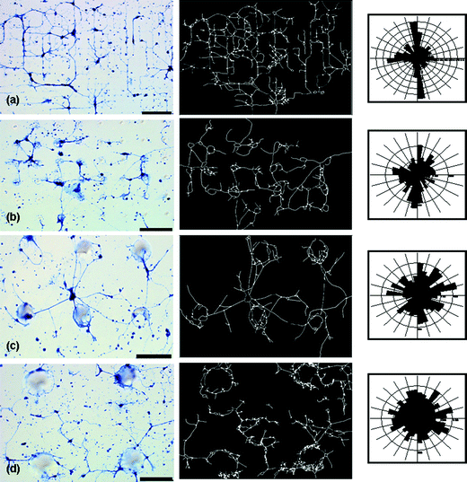 | ||
| Fig. 4 Optical micrographs, at the same magnification and light settings, of hippocampal neurons plated on glass substrates patterned with conical posts of PDMS (first column), corresponding trace of neuronal networks on patterned substrates (Neurolucida) (middle column) and subsequent polar histograms (third column) representing branching angle characteristics of the neuronal network (Neurolucida Explorer) created from each trace are presented. Polar histograms visually represent the amount of process length (scaled to total process length for each examined cell network) at a given branching angle range. (a) 10 µm diameter, 10 µm spacing; (b) 20 µm diameter, 40 µm spacing; (c) 50 µm diameter, 100 µm spacing; and (d) 100 µm diameter, 200 µm spacing. Scale bar is 90 µm. | ||
Another interesting morphological behavior is evidenced suggestively in these images (and examined more explicitly in the data presented in Fig. 5), that the cell somas show a weak but distinct preference to congregate around the edges of a post and either direct their process around and/or up the post depending on where the cell soma was located. This wrapping behavior, which progressively competes with spanning, was most apparent on the tallest features considered in the study (the 6 and 14–20 µm tall conical features present on the 50 and various 100 µm post design substrates, respectively).
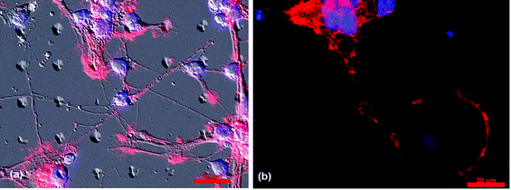 | ||
| Fig. 5 Optical micrographs of hippocampal neurons plated on glass substrates patterned with PDMS conical features. (a) A brightfield micrograph of a 10 µm diameter by 10 µm spacing PDMS pattern overlaid onto an optical fluorescence micrograph (to aid in visualization of the pattern) of the neuronal network, highlighting the preference of both the soma and processes to maximize interactions with the PDMS posts. (b) The fluorescence micrograph of neurons on a 50 µm diameter by 100 µm spacing PDMS pattern highlights similar behavior of the soma but distinct behavior in regards to process outgrowth; in the latter case, process wrapping dominates the outgrowth behavior. Also, in (b) a cell soma can be seen attached to the top of the PDMS post. In these, images, Rhodamine-phalloidin stains the actin in the cytoskeleton red, while DAPI stains the DNA in the nucleus blue. Scale bar is 20 µm. | ||
Polar histograms, representing the amount of process length (scaled to total process length for each examined cell network) at a given branching angle range, are given for each accompanying neuron trace in third column of Fig. 4. These plots highlight the behavioral transition between aligned branching, process looping, and randomized growth as the feature size is increased. At the smallest feature size, the majority of the processes branched from nodes at 0, 90, 180 or 270°. The histogram generated from the trace of the largest pattern/spacing, however, has an approximately even distribution of length at each angle range, which suggests the presence of process wrapping, randomized growth or some combination of the two. Visual inspection of the micrographs, however, established that azimuthal averaging due to process wrapping is the dominant contribution in these experiments.
Table 2 gives the average percentage of total network process length that branches from a given node at four different (approximate right) angle ranges. As can be seen from the table, the smallest feature sizes (10 × 10, 10 × 15, 15 × 10, 20 × 10) show the most aligned behavior, ranging at approximately 40–45%. The alignment becomes less prevalent on the 10 × 40 and 20 × 40 samples and is, as expected, the least prevalent in the largest feature size/spacing. To further investigate these affects, the average branching in the right angle range for the patterned samples was compared to the controls, using standard statistical methods. The smallest feature sizes, up to 20 × 10, were statistically different than the control, while the 10 × 40, 20 × 40 (and larger) samples were found to not differ statistically from the controls. Even so, this correlation does not reflect a pattern of random growth in each sample as wrapping provides a distinctly different means to azimuthally average the outgrowth direction than is true for the full planar cultures.
Fig. 5 provides further evidence of the characteristic behavior of neuron networks on the 10 × 10 and 50 × 100, as described above. The micrograph in Fig. 5(a) clearly illustrates a preference for the somatic region containing the cell nucleus (blue) to attach on (or at the edge) of the conical PDMS features. This behavior might be anticipated, for it is at such a feature that the cell soma would have the most surface area with which to interact. The processes (red) of adjacent neurons form interconnections, similar to developing neuronsin vivo.Fig. 5(b), on the other hand illustrates distinctly different behavior of the process outgrowth, one dominated by process wrapping, most likely to maximize surface interactions with the posts. This micrograph also highlights the attachment of a cell soma to the top of the post, a similar behavior to that of the somata featured in Fig. 5(a).
Neurons prefer any topography versusgrowth on smooth glass
The neuronal preference for surface topography is highlighted in Fig. 6(a), where two cell somas plated outside the patterned grid, direct their processes towards and onto the grid to maximize interactions with the post arrays. To investigate further whether this phenomenon could simply be attributed to a preference for PDMS over glass, samples with a thin layer of PDMS, treated with PDL, were also examined in this study. We observed reduced cell densities, of approximately 30 c/mm2 on these substrates versus ∼60 cells/mm2 or ∼90 cells/mm2 for the patterned or control (glass) substrates, respectively. This suggests that even though the neurons do not ‘like’ PDMS, they do ‘like’ topography, and thus will seek it out whenever possible. It should be noted here, however, that there are important ways in which the bulk PDMS substrates differ from those bearing patterns of PDMS. Perhaps most important of these is the fact that the adsorption of the activating PDL layer is inhibited by the PDMS. Its uptake is increased somewhat by oxidative pretreatments of the PDMS (such as in a UV-Ozone system—a chemistry related to that used in the decal transfer process).50 Even with such treatments, we found little improvement of the bulk PDMS systems as substrates for sustaining viable cultures.The posts provide extra surface area with which cell somas and processes can interact, but limit the amount of PDMS available to disrupt cell growth, as the PDMS is present only in the form of discrete features. We believe that when the PDMS is present in bulk, as it is for the coated samples, the presence of low molecular weight materials in the PDMS likely interferes with the cell growth.47 Thus we see a decreased survival rate on these types of samples. Our data suggests that when using PDMS to create microfabricated substrates or devices, a minimization of the material utilized is an important consideration when culturing primary mammalian neurons and that critical processing is required to preserve their viability.47
A preference for surface topography was also highlighted in the neurons response to a partial transfer of the PDMS features, Fig. 6(b). Partial transfer, in this case, means that activated PDMS was in contact with the glass substrate, but did properly attach and transfer to the surface. These “defective” samples revealed an interesting sensitivity. When neurons were grown on a substrate with PDMS features too thin to be visible with optical microscopy techniques, the neuronal processes were still able to detect a difference in topography, and thus aggregated their growth in these regions. This phenomenon was found even for cases involving complex corrugated features that independent AFM data showed ranged from approximately 20–500 nm in height. Representative AFM height profiles of these partial transfers can be found in the ESI.†
Neurons prefer to grow in networks
We observed that the neurons preferred to grow in networks, which could span 200 µm or more across the substrate. The most extensive lateral networks were observed on the smallest feature sizes. However, when neurons were isolated, they tended to have one or two short processes, regardless of the substrate they were plated on.To further illustrate the difference between isolated neurons and those in networks, a standard statistical test was performed on data (presented in the ESI†) collected from traces from both isolated neurons and neuronal networks to compare the mean process length. The p-values determined from the test showed that all but the 10 × 15, 20 × 40 and the 50 × 100 samples had statistically longer average process lengths for neurons in networks versus those that were isolated. This suggests that neurons behave most typically when in networks versus in isolation, as neurons in the developing brain, tend to form extensive networks spanning hundreds of µm or more.51
Material system has differential effect on Aplysianeuron growth
To further characterize the effect posts have on neuron growth, we chose to study the branching behavior of bag cell neurons (BCN) from Aplysia californica, to compare with the mammalian neurons investigated. When these neurons were cultured onto patterned substrates, growth differed from the hippocampal neurons, Fig. 7. These large neurons developed a complex branching pattern which though still aligned, is fundamentally different than that of the hippocampal neurons. Whereas the hippocampal neurons use the posts to direct their growth by maximizing interactions, the alignment seen in the BCN results from contact avoidance of the posts. Fig. 7 clearly illustrates the neurites preference to grow on the glass substrate between posts. This property could be exploited to direct BCN outgrowth and suggests that the material system studied here and the branching characteristics that are promoted by it are specific to neuron type.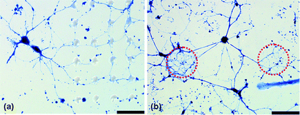 | ||
| Fig. 6 Optical micrographs of hippocampal neuron process outgrowth on PDMS post arrays, illustrating a preference for topography. (a) Neuron growth on a 15 × 10 pattern, highlighting the behavior of two cell somas, having been plated outside of the patterned mesh region, directing their processes onto the grid to interact with the PDMS features. (b) Neuron growth on an incomplete transfer of a 100 × 200 pattern, where a cell soma is seen to direct its outgrowth to interact with topography that is not visible with optical techniques. (Dashed line indicates approximately where activated PDMS came in contact with glass but did not transfer appreciably.) Scale bar is 90 µm. | ||
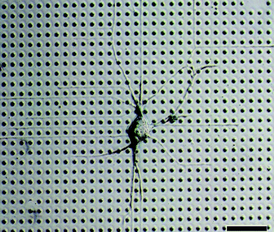 | ||
| Fig. 7 Optical micrograph of non-mammalian bag cell neurons (Aplysia californica) on a 15 × 10 array, highlighting fundamentally different outgrowth behavior versus the mammalian neurons, one which is dictated by contact avoidance of PDMS post arrays as they navigate the mesh. Scale bar is 110 µm. | ||
Discussion
The goal of this study was to characterize the behavior of early postnatal hippocampal neurons on substrates presenting a variety of textural design rules but with a common (conical) underlying shape and similar chemistry to make them growth compliant (through the addition an adsorbed layer of poly-lysine). A form of decal transfer lithography was used in this study to create substrates with discrete topographical features of various size and spacing. We found that the behavior of neurons in this environment, specifically in networks, could be tailored to display specific branching characteristics. Indeed, the characteristics of the network are controlled depending on the grid size, to obtain either an aligned or wrapped design, or a combination of the two.The feature sizes considered here are larger than those previously studied by other groups.1–12,14–21,24,25 While it may appear that features on these scales are larger than those encountered by the growing neuron, neuronal processes often extend many millimeters from the soma and may encounter tightly coupled allotypic neurons, extracellular matrix features, fusiculations or vascularizations, each of which would be larger in scale than growing neuronal processes. Even though the linear form of aligned branching is not present on the largest feature size/spacing, the branching and growth behavior is interesting at this scale. For example, the conformal adherence to the conical pillar of the process outgrowth into the z-plane is intriguing. Thus at the largest feature sizes, there is a transition from a two-dimensional to a three-dimensional architecture. These results suggest this approach can be used to develop 3D platforms, which more closely resemble the in vivo arrangement of neurons, for examining cell growth and behavior. Substrates with even larger post diameters could be easily fabricated, to allow for more extensive cell growth into the z-plane. Consequently, the fabrication method used here has the potential to be used in future 3D cell culture studies, as it provides a simple, inexpensive, flexible method for creating host substrates.
It is clear from the data collected in this study that developing hippocampal neurons prefer to grow in networks. Irrespective of the design rule, plating at densities that enable multi-cellular contacts always produced the most viable cultures. In these cases, the contact guidance provided by the substrate led to a variety of significant morphological outcomes. As the plated neurons developed processes, they tended to form extensive networks, especially on the smallest feature sizes, as they both stabilized contacts with the next nearest post and grew to interact with other neighboring neurons. These networks featured both significant extensions and dense branching. It would seem as a result that this type of material system, one with discrete attachment points, promotes more naturalistic neuronal interactions in vitro.
As these types of patterns can promote expansive organized neuronal networks, we believe they will facilitate studies directed at important questions in neuronal biology. Our work is particularly motivated by the chemical and biological features that underpin mechanisms of neuronal repair. The system described here appears to hold potential for such investigations as it would allow one to damage processes at discrete locations within the network and the resulting electrical and chemical signals collected and analyzed with various techniques. Damaging a neuron in a network would generate more pertinent information on how a neuron reacts upon incursion of an injury in vivo.
Our discovery that topography strongly organizes the pattern in which neuronal processes are stabilized predicts that it will be interesting to further explore the rules for orientation of neuronal growth elicited on the patterns. For example, do the neurons typically interact with each other dendrite-to-dendrite, dendrite-to-axon or axon-to-axon? Do the neurons tend to grow or move coordinately in the same direction across the pattern? This information would allow for optimization of the design parameters in order to guide the localized expression of mammalian neurons.
It is interesting to note the significant differential sensitivity we found regarding the source of neuronal cells cultured on the patterned arrays. Aplysianeurons have become a widely embraced model for neuronal growth, repair, and reorganization during learning,36–42 with several reports investigating their properties on engineered substrates and controlled architectures.43–46 It is interesting to speculate whether the differences observed here between the mature Aplysia bag cell neurons and early post-natal rat hippocampal neurons reflect differences between these two species, are due to differences in the specific neuronal subtypes used, differences in the developmental state of the respective neurons or whether such differences would be found if other mammalian neuronal types were investigated. Additional work is needed to clarify questions such as these and to develop appropriate platforms for neuron-specific behaviors.
Conclusions
We have developed a material system that can be manipulated to tailor neuronal outgrowth in a defined manner. Although large feature sizes have not been vigorously studied previously in relation to contact guidance, they should not be disregarded. Neuronal development on larger feature sizes tended to display process wrapping and interactions in the z-plane, while process outgrowth on the smallest feature sizes tended to promote extensive aligned, polarized networks. As might be expected, we found that neurons survive best when allowed to grow in networks.As guidance is observed across a surprising range of distances, an intriguing question involves the mechanism of this long-distance guidance. During process extension from a growth cone, filipodia extend and sample many areas during a series of extensions and retractions. Permissible environments would promote transformation of the filopodia into a stable process extension. In neurons that have disrupted filipodia, growth cones still extend but direction becomes irregular,52,53 indicating that these directional cues affect filipodia. By investigating these effects using other materials besides PDMS/PDL, it should be possible to determine whether the guidance is due to filipodia interacting with surface topology alone or due to combination of topographic and chemical differences between the materials making up the pillars and substrate.
Acknowledgements
This work was supported by the Wm. Keck Foundation and through P30 DA-018310 to the UIUC Neuroproteomics Center on Cell to Cell Signaling. We thank Robert Shepherd for aid with Fig. 1, and the Imaging Technology Group at Beckman Institute, especially Jon Ekman and Scott Robinson, for their help with imaging. We express gratitude to members of the Gillette lab, specifically Dr. Jennifer Mitchell and Karen Weis for invaluable advice and discussion and Larry Millet for primary neuron culture training.References
- I. Nagata, A. Kawana and N. Nakatsuji, Development, 1993, 117, 401–408 CAS.
- B. Wojciak-Stothard, Z. Madeja, W. Korohoda, A. Curtis and C. Wilkinson, Cell Biol. Int., 1995, 19, 485–490 CrossRef CAS.
- B. Wojciak-Stothard, A. Curtis, W. Monaghan, K. MacDonald and C. Wilkinson, Exp. Cell Res., 1996, 223, 426–435 CrossRef CAS.
- E. T. den Braber, J. E. de Ruijter, L. A. Ginsel, A. F. von Recum and J. A. Jansen, Biomaterials, 1996, 17, 2037–2044 CrossRef CAS.
- A. M. Rajnicek, S. Britland and C. D. McCaig, J. Cell Sci., 1997, 110, 2905–2913.
- S. Britland, C. Perridge, M. Denyer, H. Morgan, A. Curtis and C. Wilkinson, Experimental Biology Online, 1997, 1, 1–15 Search PubMed.
- E. T. den Braber, J. E. de Ruijter, L. A. Ginsel, A. F. von Recum and J. A. Jansen, J. Biomed. Mater. Res., 1998, 40, 291–300 CrossRef CAS.
- X. F. Walboomers, W. Monaghan, A. S. G. Curtis and J. A. Jansen, J. Biomed. Mater. Res., 1999, 46, 212–220 CrossRef CAS.
- X. F. Walboomers, H. J. E. Croes, L. A. Ginsel and J. A. Jansen, J. Biomed. Mater. Res., 1999, 47, 204–212 CrossRef CAS.
- E. Stepien, J. Stanisz and W. Korohoda, Cell Biol. Int., 1999, 23, 105–116 CrossRef CAS.
- A. M. P. Turner, N. Dowell, S. W. P. Turner, L. Kam, M. Isaacson, J. N. Turner, H. G. Craighead and W. Shain, J. Biomed. Mater. Res., 2000, 51, 430–441 CrossRef CAS.
- J. A. Alaerts, V. M. De Cupere, S. Moser, P. Van Den Bosh deAguilar and P. G. Rouxhet, Biomaterials, 2001, 22, 1635–1642 CrossRef CAS.
- M. Merz and P. Fromherz, Adv. Mater., 2002, 14, 141–144 CrossRef CAS.
- Y. W. Fan, F. Z. Cui, S. P. Hou, Q. Y. Xu, L. N. Chen and I. S. Lee, J. Neurosci. Meth., 2002, 120, 17–23 CrossRef CAS.
- A. I. Teixeira, G. A. Abrams, P. J. Bertics, C. J. Murphy and P. F. Nealey, J. Cell Sci., 2003, 116, 1881–1892 CrossRef CAS.
- N. M. Dowell-Mesfin, M.-A. Abdul-Karim, A. M. P. Turner, S. Schanz, H. G. Craighead, B. Roysam, J. N. Turner and W. Shain, J. Neural Eng., 2004, 1, 78–90 Search PubMed.
- L. A. Cystera, K. G. Parker, T. L. Parker and D. M. Granta, Biomaterials, 2004, 25, 97–107 CrossRef.
- U. Pimpon, G. K. Toworfe, F. Dietrich, P. L. Lelkes and R. J. Composto, J. Biomed. Mater. Res. A, 2005, 75A, 668–680 CrossRef.
- N. Li and A. Folch, Exp. Cell Res., 2005, 311, 307–316 CrossRef CAS.
- J. D. Foley, E. W. Grunwalda, P. F. Nealey and C. J. Murphy, Biomaterials, 2005, 26, 3639–3644 CrossRef CAS.
- K. Faid, R. Voicu, M. Bani-Yaghoub, R. Tremblay, G. Mealing and C. R. Barjovan, Biomed. Microdevices, 2005, 7, 179–184 CrossRef CAS.
- O. du Roure, A. Saez, A. Buguin, R. H. Austin, P. Chavrier, P. Silberzan and B. Ladoux, P. Natl. Acad. Sci. USA, 2005, 102, 2390–2395 Search PubMed.
- M. Bani-Yaghoub, R. Tremblay, R. Voicu, G. Mealing, R. Monette, C. Py, K. Faid and M. Sikorska, Biotechnol. Bioeng., 2005, 92, 2005.
- F. Johansson, P. Carlberg, N. Danielsen, L. Montelius and M. Kanje, Biomaterials, 2006, 27, 1251–1258 CrossRef CAS.
- N. Gomez, Y. Lub, S. Chen and C. E. Schmidt, Biomaterials, 2007, 28, 271–284 CrossRef CAS.
- Y. Xia and G. M. Whitesides, Polymeric Materials Science and Engineering, 1997, 77, 596–598 Search PubMed.
- Y. Xia and G. M. Whitesides, Angewandte Chemie International Edition, 1998, 37, 550–575 Search PubMed.
- G. M. Whitesides, E. Ostuni, S. Takayama, X. Jiang and D. E. Ingber, Annu. Rev. Biomed. Eng., 2001, 3, 335 CrossRef CAS.
- J. A. Rogers and R. G. Nuzzo, Materials Today, 2005, 8, 50–56 CrossRef CAS.
- M. Rothschild, Materials Today, 2005, 8, 18–24 CrossRef CAS.
- K. Ronse, C. R. Phys., 2006, 7, 844–857 Search PubMed.
- W. R. Childs and R. G. Nuzzo, Adv. Mater., 2004, 16, 1323–1327 CrossRef CAS.
- W. R. Childs and R. G. Nuzzo, Langmuir, 2005, 21, 195–202 CrossRef CAS.
- W. R. Childs and R. G. Nuzzo, J. Am. Chem. Soc., 2002, 124, 13583–13596 CrossRef CAS.
- W. R. Childs, M. J. Motala, K. J. Lee and R. G. Nuzzo, Langmuir, 2005, 21, 10096–10105 CrossRef CAS.
- S. Schacher, J Neurosci., 1985, 5, 2028–2034 CAS.
- S. S. Lin and I. B. Levitan, Science, 1987, 237, 648–650 CrossRef CAS.
- G. A. Clark and E. R. Kandel, Proc Natl Acad Sci U S A., 1993, 90, 11411–11415 CrossRef CAS.
- D. Benbassat and M. E. Spira, Eur J Neurosci., 1994, 6, 1605–1614 CrossRef CAS.
- D. J. Goldberg and D. Y. Wu, J Neurobiol., 1995, 27, 553–560 CrossRef CAS.
- R. D. Fields and K. Itoh, Trends Neurosci., 1996, 19, 473–480 CrossRef CAS.
- S. S. Bedi, A. Salim, S. Chen and D. L. Glanzman, J Neurophysiol., 1998, 79, 1371–1383 CAS.
- E. V. Romanova, K. A. Fosser, S. S. Rubakhin, R. G. Nuzzo and J. V. Sweedler, FASEB J., 2004, 18, 1267–1269 CAS.
- E. V. Romanova, S. P. Oxley, S. S. Rubakhin, P. W. Bohn and J. V. Sweedler, Biomaterials, 2006, 27, 1665–1669 CrossRef CAS.
- A. Cohen, J. Shappir, S. Yitzchaik and M. E. Spira, Biosens. Bioelectron., 2006, 22, 656–663 CrossRef CAS.
- J. Kyubong, M. L. Heien, L. B. Thompson, M. Zhong, R. G. Nuzzo and J. V. Sweedler, Lab Chip, 2007, 7, 1454–1460 RSC.
- L. J. Millet, M. E. Stewart, J. V. Sweedler, R. G. Nuzzo and M. U. Gillette, Lab Chip, 2007, 7, 987–994 RSC.
- G. J. Brewer, J. Neurosci. Meth., 1997, 71, 143–155 CrossRef CAS.
- W. S. Rasband, U.S. National Institute of Health, 1997–2007 Search PubMed.
- K. Efimenko, W. E. Wallace and J. Genzer, J. Colloid Interf. Sci., 2002, 254, 306–315 CrossRef CAS.
- J. G. Nicholls, A. R. Martin, B. G. Wallace and P. A. Fuchs, From Neuron to Brain, Sinauer Associates Inc, Sunderland, MA, 2001 Search PubMed.
- D. Bentley and A. Toroian-Raymond, Nature, 1986, 323, 712–715 CrossRef CAS.
- T. M. Gomez and P. C. Letourneau, J Neurosci., 1994, 14, 5959–5972 CAS.
Footnote |
| † Electronic supplementary information (ESI) available: Supplementary figures and tables. See DOI: 10.1039/b803595d |
| This journal is © The Royal Society of Chemistry 2009 |