DOI:
10.1039/B815055A
(Paper)
J. Mater. Chem., 2009,
19, 70-74
Accessibility of cylindrical channels within patterned mesoporous silica films using nanoparticle diffusion
Received
28th August 2008
, Accepted 2nd October 2008
First published on 12th November 2008
Abstract
Mesoporous silica films with well ordered nanochannels (approximately 7 nm in diameter) oriented parallel to the substrate were synthesized using supercritical carbon dioxide mediated silica deposition within templates comprised of triblock copolymers blended with strongly associating homopolymers. The films were patterned at the device level by conventional lithography and etched to yield periodic circular features approximately 20 µm in diameter. The nanoscale channels remained accessible to penetrant diffusion as shown by dye uptake experiments. The nanochannel arrays were used as miniature size exclusion columns to mediate nanoparticle diffusion.
Introduction
Mesoporous metal oxide films have applications in microelectronics, sensing, catalysis, separation, and optoelectronics.1–5 Precise patterning of mesostructured films on the substrate and control of spatial orientation of mesopores on the surface are essential prerequisites to utilize periodic arrays of well-defined nanovoids in most of these applications.6 Many techniques are devoted to the preparation of patterned mesoporous silica films including micromolding in capillaries (MIMIC),7–10 direct UV or X-ray lithography,11–15micropen lithography (MPL),16,17 ink-jet printing,18dip-pen nanolithography (DPN),19–21 site-selective deposition via the underlying chemical modified substrate22,23 and conventional photolithography.24,25 While mesoporous silica films can be patterned at the device scale, several disadvantages of current technologies associated with pattern fabrication still need to be circumvented. For instance, the soft lithographic-related techniques like MIMIC require a lengthy processing time, from hours to a day, for patterning of mesoporous films.26,27 The rapid prototyping procedure of MPL could be used for patterning of hierarchical organized mesostructures within seconds, however, writing in a large area is still a time consuming process. Moreover, the formation of mesoporous structures on most aforementioned technologies is driven by the principle of evaporation-induced self-assembly (EISA), which is an equilibrium result from interfacial interaction and silica condensation.28 This process complicates the formation of patterns with desired mesoporous structure in certain applications. Changes in the mesophases are also commonly observed in mesoporous silica films during thermal calcination or UV irradiation.12,29 It has been documented that the hexagonally packed porous structure of a silica film was transformed to tetragonal packing in a region exposed to UV light.13 An efficient way of patterning mesoporous silica films with controllable pore orientation is in demand for the applications that involves utilization of confined nanospace.
Our group has developed a new approach for formation of mesoporous metal oxide by selective deposition of silica in a block copolymer film dialyzed by supercritical carbon dioxide (scCO2).30–32 Unlike EISA, this novel strategy allows pre-organization of the template by decoupling the metal-oxide condensation and the template self-assembly. By replicating a block co-polymer 3D structure, we are able to fabricate a mesoporous silica film with channels parallel to the substrate with increased long range order using a polymer blend of Pluronic F127 (PEO106–PPO70–PEO106) and poly(acrylic acid) (PAA) or poly(4-hydroxystyrene) (PHOST). We note that because template formation and silica deposition are decoupled, a range of suitable templates are accessible.30–34 Furthermore, channel diameters can be tailored over broad ranges by adjusting the template molecular weight.35 Herein, we reported a facile method of patterning mesostructured films by integration of both conventional photolithography and scCO2-assisted formation of mesoporous silica films.
Result and discussion
Fabrication and characterization of patterned mesoporous silica films
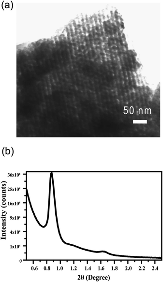
We prepared a patterned mesoporous silica film by integration of both “top-down” and “bottom-up” approaches as shown in Fig. 1. A strongly phase-segregated block polymer film was spun-cast on the silicon wafer using blend template of a triblock copolymer (Pluronic F127) and a low molecular weight homopolymer (PAA). The hierarchical block copolymer structure was then replicated by selective deposition of silica in the hydrophilic PEO domains followed by calcination at 400 °C to yield a smooth mesoporous silica film with nanochannels aligned parallel to the silicon substrate. The sample was UV irradiated through a photomask on a positive tone resist layer that was spun-cast on the aforementioned silica film. After developing, circular patterns with diameter ∼20 µm were generated. Reactive ion etching (RIE) of the composite film with carbon tetrafluoride (CF4) etched the silica layer while the photoresist protecting layer transferred patterns to the mesoporous silica film. Transmission electron microscopy (TEM) (Fig. 2a) reveals mesochannels of approximately 7 nm diameter that are indicative of selective silica replication of polymer template structures. X-Ray diffraction (XRD) analysis (Fig. 2b) reveals a large (100) peak with d-spacing of approximately 10 nm (d = nλ/[2sinθ]). Utilizing the approximate pore size (7 nm) from the TEM image, d-spacing from the XRD, and assuming the sample contains ideally hexagonally packed MCM-41 type mesopores, the wall thickness is about 4.5 nm. However, it is known that pore shrinkage will occur after calcination and the sample will deviate from the ideal case. Measuring surface area via gas absorption is problematic due to the small amount of material associated with thin films.
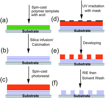 |
| | Fig. 1 A schematic representation for the fabrication of mesoporous silica patterns with parallel nanochannels. The template of block copolymer films (a) is obtained through spin coating a polymer blend of triblock copolymer and homopolymer with an acid catalyst. Selective silica infusion occurred in the humidified scCO2, and then calcined to yield a mesoporous silica film (b). The sacrificial photoresist was spun cast on the resulting porous films (c), followed by UV exposure with photomask to generate surface patterns (d). Post development formed pillars of photoresist to protect the underlying mesoporous silica film (e). The patterned mesoporous silica is obtained through reactive ion etching followed by an acetone/isopropanol wash. | |
The influence of etching time on etch depth for the patterned mesoporous silica film was investigated using profilometer measurements. The thickness of the silica film increases as the etching time extends. It is worth mentioning that the thickness of calcined mesoporous silica films before coating with photoresist is 400–500 nm. The F127 templated sample etched for 15 sec already had reached the silicon layer. The etched pattern to be examined is displayed in Fig. 3. This optical micrograph (Fig. 3a) exhibits a patterned mesoporous silica film with regularly repeated circular units having micro-sized features in accordance with the photomask. Additionally, the scanning electron microscopy (SEM) micrograph shows this array in more detail (Fig. 3b).
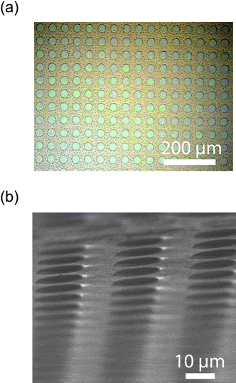 |
| | Fig. 3 (a) Optical micrograph showing the typical size scale and format of the samples. (b) SEM micrograph of the mesoporous silica array prepared with a 15 second etch. | |
Accessibility of nanochannels in patterned mesoporous silica films
The accessibility of mesochannels in regular circular patterns was examined by impregnation of a fluorescent dye within the mesoporous silica films. In this study, we specifically chose a positively charged Rhodamine-6G dye with a diameter of 1.34 nm, which should diffuse into the channel and absorb on the silica framework through complementary electrostatic interaction. The confocal laser scanning microscopy (LSM) image of Rhodamine-6G infused mesoporous silica film exhibits an array of green fluorescent dots with feature size of approximately 20 µm. This corresponds to the size of lithographically patterned silica domains (Fig. 4). The dark background indicates that no nonspecific adsorption occurred between the Rhodamine 6G dye and silica surface. The result demonstrated accessibility of mesoporous structures in the patterned silica matrix after the photolithographic process. The accessibility of mesochannels originated from a reduced diffusion pathway due to the miniaturization of silica domain sizes.
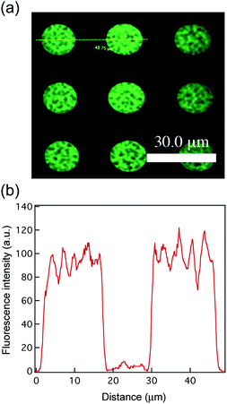 |
| | Fig. 4 (a) The fluorescence image of mesoporous silica patterns after uptaking Rhodamine 6G dye was obtained by confocal LSM. (b) The line profile displays the dye distribution inside the features. | |
Size selectivity of patterned mesoporous silica films
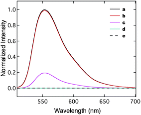
The accessibility of mesochannels in the silica pattern offers an opportunity to regulate diffusion of particles based on relative sizes of these particles compared to the mesopores. We performed several fluorescence-quenching experiments of dye-infused silica films by gold nanoparticles (GNPs) with various sizes to verify the size-exclusion effect. Gold nanoparticles are well known for their superb ability as fluorescence quenchers. GNPs that are smaller than the pore diameter can freely diffuse into the channels and quench the fluorescence of entire mesoporous films. Larger sized GNPs are excluded from channels and can only quench fluorophores adsorbed on the external surface. We synthesized two populations of water-soluble GNPs with 2 nm (monolayer protected) and 14 nm (citrate stabilized) cores according to reported methods.36,37 Since the quenching ability of GNPs to fluorophores is dependent on particle sizes, we studied the quenching efficiency of each GNP against Rhodamine 6G dye in solution to ensure that two separate samples are comparable using a fluorescence spectrophotometer. As indicated in Fig. 5, the fluorescence intensity of the Rhodamine 6G solution significantly decreased in the presence of GNP-14 nm at 2.37 nM. However, GNP-2 nm at the same concentration only quenched 2% of fluorescence. The GNP-2 nm solution with higher concentration (16 µM) successfully quenched the fluorescence. The quenching efficiency of GNP-14 nm exceeds 6.7 × 10³ times than that of GNP-2 nm for the Rhodamine 6G dye in the examined concentration range.
Quenching experiments of Rhodamine 6G infused mesoporous silica films were based on the optimized concentrations of each GNP quencher. The dye-infused mesoporous patterns prepared from F127 were placed in GNP-2 nm solution and displayed considerable quenching of fluorescence after soaking in the GNP solution for 2 days. However, the fluorescence intensity of the same film in GNP-14 nm solution only slightly decreased due to the surface quenching by GNPs (Fig. 6). Considering the bulkiness of large GNPs, the absence of quenching phenomena in GNP-14 nm solution might also originate from hindered diffusion. Therefore, the mesoporous silica film was further immersed in the GNP-14 nm solution for 2 weeks. The resulting film continues to exhibit moderate fluorescence intensity, which eliminates this possibility (Fig. 7a). A patterned silica film synthesized from Pluronic F108 template consists of isolated spherical voids in the silica matrix. These closed voids are not accessible to the GNPs. This silica film can be thought of as a “pseudo solid” material. The solution of GNP-14 nm should be able to quench the fluorescence of surface adsorbed dyes on this control sample. Before the introduction of GNPs, F108-templated silica patterns in Rhodamine 6G dye displayed strong fluorescence. However, as predicted the fluorescence was significantly quenched after immersion of the F108 sample in the GNP-14 nm solution (Fig. 7b). Combined with the aforementioned observations, we demonstrated control of substrate diffusion in and out of porous structures physically constrained by the pore entrances.
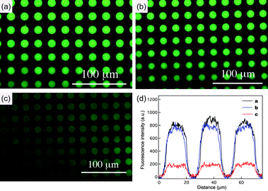 |
| | Fig. 6 (a) The fluorescence image of dye-infused (Rhodamine 6G = 0.1 µM) mesoporous silica patterns synthesized from F127. Fluorescence images of mesoporous silica patterns after soaking with (b) GNP-14 nm (2.37 nM) and (c) GNP-2 nm (16 µM). (d) Line profile comparing the intensities of mesoporous silica patterns (a), (b) and (c). | |
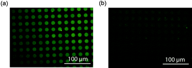 |
| | Fig. 7 (a) A mesoporous silica pattern prepared from F127 that was soaked for 2 weeks in GNP-14 nm (2.37 nM). (b) Sample prepared from F108 after soaking with GNP-14 nm (2.37 nM) for 2 weeks. | |
Conclusions
In summary, we integrated both photolithography and supercritical CO2 assisted selective deposition of silica on self-assembled mixed polymer templates to fabricate mesoporous silica patterns with parallel channels. The patterned mesoporous silica features with domain sizes of micrometers facilitate diffusion of substrates as shown in the dye-uptake experiments. In addition, these ordered mesoporous silica patterns can serve as size exclusion columns for discrimination of nanoparticles as shown in this work, whose properties are beneficial for the separation of biomolecules of interest. Meanwhile, we are looking toward controlling the pore size through the block copolymer molecular weight to generate a series of discrete channel diameters. Because the templating and infusion steps are decoupled in the supercritical fluid infusion route to mesoporous films we expect to access a very broad range of templates and therefore channel diameters.
Experimental
All chemicals, except the following reagents, are purchased from Sigma-Aldrich Inc. and used as received without further purification. Triblock copolymers of poly(ethylene oxide)106–poly(propylene oxide)70–poly(ethylene oxide)106 (Pluronic F127) and poly(ethylene oxide)127–poly(propylene oxide)48–poly(ethylene oxide)127 (Pluronic F108) are obtained from BASF. The photoresist, S1813, and Developer 351 are purchased from Rohm and Haas Electronic Materials. The silicon wafer was obtained from University Wafer. The film thickness was measured using an interferometer (Filmetrics) or a profilometer (Dektak 150). Transmission electron microscopy (TEM) specimens of mesoporous silica patterns are prepared by scraping material from the substrate. The scraped material is ground, suspended in ethanol, and then transferred onto a carbon-coated copper grid to be examined using a JEM-2000FX II. The silica samples examined by scanning electron microscopy (SEM) are prepared by splitting the wafer and mounting the sample perpendicularly in a trench. The mounts are platinum coated for 4 minutes and images are collected using a JSM-6320 FXV. XRD spectra are collected using a PANalytical X'Celerator using Cu K-α radiation (λ = 0.154 nm) with a 1/16 divergence slit and copper filter.
Preparation of mesoporous silica films
A polymer blend of amphiphilic block copolymers of Pluronic F127 or Pluronic F108 with 16–20 wt% poly(acrylic acid) (PAA, Mw = 1800) were used as templates for generating mesoporous silica films. A solution of Pluronic/PAA with 5 wt% p-toluenesulfonic acid (pTSA) in a mixture of ethanol/water (v/v = 50/50) were spun-cast onto 50.8 mm diameter silicon substrates. The spinning rate and time were maintained at 2000 rpm and 60 sec to yield a polymer film with an approximate thickness of 400–500 nm. The substrate was placed in a high-pressure reactor with a few drops of water and annealed at 60 °C for 10 min. After annealing, the silica precursor, tetraethyl orthosilicate (TEOS, 7 µL) was introduced into the reactor, followed by injection of scCO2 (Merriam Graves Coleman grade) at 60 °C and 124 bar. The reactor was pressurized over 1.5 hr, held at the final conditions for 30 min, and depressurized slowly overnight. The organic templates were removed through calcination at 400 °C for 6 hr with a ramp rate of 1.67 °C/min to obtain a smooth mesoporous silica film.
The positive tone photoresist (S1813) was spun onto the mesoporous silica films at 3000 rpm for 30 sec and baked at 100 °C for 75 sec. The substrate was then exposed with UV light (Hg lamp, 20 watts/cm2) at 365 nm for 4.5 sec using a mask aligner (SUSS Microtec) with low vacuum contact. A quartz mask with 25 µm opaque circles was used for the patterning. After irradiation, the samples were developed using a mixture of water/Developer 351 (v/v = 4:1) yielding pillars with a height of 1.5 µm. Reactive ion etching (RIE, Trion) was completed at 100 mTorr with an RIE setting of 150 watts using a gas mixture of carbon tetrafluoride (CF4) (45 sccm) and oxygen (5 sccm) between 5 and 40 sec. The remaining photoresist was removed by generously washing with acetone.
Infusion of Rhodamine 6G dye
A patterned mesoporous silica film, prepared from RIE for 20 sec, was placed in an aqueous solution of Rhodamine 6G (0.1 µM, ε260 nm = 8.02 × 10⁴ M−1cm−1) for 5 min, followed by washing with copious amount of water and ethanol, then dried with N2 gas. The resulting dye-uptake silica film was subjected to study by fluorescence microscopy and confocal laser scanning microscopy.
Quenching fluorescence of the Rhodamine 6G solution with gold nanoparticles
The gold nanoparticles with 14 nm core (GNP-14 nm) were synthesized according to the reported procedure.36 Smaller GNPs with a core diameter of 2 nm were prepared based on the published method, followed by place-exchange with 6-mercapto-N,N,N-trimethyl hexane-1-ammonium to yield water soluble cationic gold nanoparticles (GNP-2 nm).37 The fluorescence of Rhodamine 6G dye (0.1 µM) was quenched with either 2 nm or 14 nm gold nanoparticles at various concentrations and observed with an excitation wavelength at 500 nm.
Dye up-taken mesoporous silica patterns were prepared from 0.1 µM solution of Rhodamine 6G. Concentrations of individual GNPs were chosen based on the aforementioned quenching study in solution (GNP-14 nm = 2.37 nM and GNP-2 nm = 16.0 µM). The patterned silica film was split and immersed in each GNP solution for the same amount of time. The fluorescence intensity of silica patterns after quenching by GNPs was observed by fluorescence microscopy.
Acknowledgements
We gratefully acknowledge financial support from the National Science Foundation (NSF) through the Center for Hierarchical Manufacturing (CHM) (CMMI-053171) and (CBET 0529034).
References
- A. Corma, Chem. Rev., 1997, 97, 2373–2419 CrossRef CAS.
- M. E. Davis, Nature, 2002, 417, 813–821 CrossRef CAS.
- F. Schuth and W. Schmidt, Adv. Mater., 2002, 14, 629–638 CrossRef CAS.
- A. Stein, Adv. Mater., 2003, 15, 763–775 CrossRef CAS.
- G. Wirnsberger, P. D. Yang, B. J. Scott, B. F. Chmelka and G. D. Stucky, Spectrochim. Acta, Part A, 2001, 57, 2049–2060 CrossRef CAS.
- P. Innocenzi, T. Kidchob, P. Falcaro and M. Takahashi, Chem. Mater., 2008, 20, 607–614 CrossRef CAS.
- P. D. Yang, T. Deng, D. Y. Zhao, P. Y. Feng, D. Pine, B. F. Chmelka, G. M. Whitesides and G. D. Stucky, Science, 1998, 282, 2244–2246 CrossRef CAS.
- P. D. Yang, A. H. Rizvi, B. Messer, B. F. Chmelka, G. M. Whitesides and G. D. Stucky, Adv. Mater., 2001, 13, 427–431 CrossRef CAS.
- P. D. Yang, G. Wirnsberger, H. C. Huang, S. R. Cordero, M. D. McGehee, B. Scott, T. Deng, G. M. Whitesides, B. F. Chmelka, S. K. Buratto and G. D. Stucky, Science, 2000, 287, 465–467 CrossRef CAS.
- M. Trau, N. Yao, E. Kim, Y. Xia, G. M. Whitesides and I. A. Aksay, Nature, 1997, 390, 674–676 CAS.
- F. Cagnol, D. Grosso, G. Soler-Illia, E. L. Crepaldi, F. Babonneau, H. Amenitsch and C. Sanchez, J. Mater. Chem., 2003, 13, 61–66 RSC.
- A. M. Dattelbaum, M. L. Amweg, L. E. Ecke, C. K. Yee, A. P. Shreve and A. N. Parikh, Nano Lett., 2003, 3, 719–722 CrossRef.
- D. A. Doshi, N. K. Huesing, M. C. Lu, H. Y. Fan, Y. F. Lu, K. Simmons-Potter, B. G. Potter, A. J. Hurd and C. J. Brinker, Science, 2000, 290, 107–111 CrossRef CAS.
- Y. F. Lu, Y. Yang, A. Sellinger, M. C. Lu, J. M. Huang, H. Y. Fan, R. Haddad, G. Lopez, A. R. Burns, D. Y. Sasaki, J. Shelnutt and C. J. Brinker, Nature, 2001, 410, 913–917 CrossRef CAS.
- L. Malfatti, T. Kidchob, S. Costacurta, P. Falcaro, P. Schiavuta, H. Amenitsch and P. Innocenzi, Chem. Mater., 2006, 18, 4553–4560 CrossRef CAS.
- H. Y. Fan, Y. F. Lu, A. Stump, S. T. Reed, T. Baer, R. Schunk, V. Perez-Luna, G. P. Lopez and C. J. Brinker, Nature, 2000, 405, 56–60 CrossRef.
- H. Y. Fan, S. Reed, T. Baer, R. Schunk, G. P. Lopez and C. J. Brinker, Microporous Mesoporous Mater., 2001, 44, 625–637 CrossRef.
- M. Mougenot, M. Lejeune, J. F. Baumard, C. Boissiere, F. Ribot, D. Grosso, C. Sanchez and R. Noguera, J. Am. Ceram. Soc., 2006, 89, 1876–1882 CrossRef CAS.
- S. H. Hong, J. Zhu and C. A. Mirkin, Science, 1999, 286, 523–525 CrossRef CAS.
- C. A. Mirkin, Science, 1999, 286, 2095–2096 CrossRef CAS.
- R. D. Piner, J. Zhu, F. Xu, S. H. Hong and C. A. Mirkin, Science, 1999, 283, 661–663 CrossRef CAS.
- A. Hozumi, H. Sugimura, K. Hiraku, T. Kameyama and O. Takai, Nano Lett., 2001, 1, 395–399 CrossRef CAS.
- H. Sugimura, A. Hozumi, T. Kameyama and O. Takai, Adv. Mater., 2001, 13, 667–670 CrossRef CAS.
- F. K. de Theije, A. R. Balkenende, M. A. Verheijen, M. R. Baklanov, K. P. Mogilnikov and Y. Furukawa, J. Phys. Chem. B, 2003, 107, 4280–4289 CrossRef CAS.
- J. A. Paik, S. K. Fan, C. J. Kim, M. C. Wu and B. Dunn, J. Mater. Res., 2002, 17, 2121–2129 CrossRef CAS.
- B. D. Gates, Q. B. Xu, M. Stewart, D. Ryan, C. G. Willson and G. M. Whitesides, Chem. Rev., 2005, 105, 1171–1196 CrossRef CAS.
- Y. N. Xia and G. M. Whitesides, Annu. Rev. Mater. Sci., 1998, 28, 153–184 CrossRef CAS.
- C. J. Brinker, Y. F. Lu, A. Sellinger and H. Y. Fan, Adv. Mater., 1999, 11, 579–585 CrossRef CAS.
- T. Clark, J. D. Ruiz, H. Y. Fan, C. J. Brinker, B. I. Swanson and A. N. Parikh, Chem. Mater., 2000, 12, 3879–3884 CrossRef.
- R. A. Pai, R. Humayun, M. T. Schulberg, A. Sengupta, J. N. Sun and J. J. Watkins, Science, 2004, 303, 507–510 CrossRef CAS.
- R. A. Pai and J. J. Watkins, Adv. Mater., 2006, 18, 241–245 CrossRef CAS.
- B. D. Vogt, R. A. Pai, H. J. Lee, R. C. Hedden, C. L. Soles, W. L. Wu, E. K. Lin, B. J. Bauer and J. J. Watkins, Chem. Mater., 2005, 17, 1398–1408 CrossRef CAS.
- V. R. Tirumala, R. A. Pai, S. Agarwal, J. J. Testa, G. Bhatnagar, A. H. Romang, C. Chandler, B. P. Gorman, R. L. Jones, E. K. Lin and J. J. Watkins, Chem. Mater., 2007, 19, 5868–5874 CrossRef CAS.
- S. Nagarajan, J. K. Bosworth, C. K. Ober, T. P. Russell and J. J. Watkins, Chem. Mater., 2008, 20, 604–606 CrossRef CAS.
- S. Nagarajan, L. M., R. A. Pai, J. K. Bosworth, P. Busch, D. M. Smilgies, C. K. Ober, T. P. Russell and J. J. Watkins, Adv. Mater., 2008, 20, 246–251 CrossRef CAS.
- K. C. Grabar, R. G. Freeman, M. B. Hommer and M. J. Natan, Anal. Chem., 1995, 67, 735–743 CrossRef CAS.
- A. Verma, J. M. Simard, J. W. E. Worrall and V. M. Rotello, J. Am. Chem. Soc., 2004, 126, 13987–13991 CrossRef CAS.
Footnote |
| † These authors equally contributed to this work. |
|
| This journal is © The Royal Society of Chemistry 2009 |
Click here to see how this site uses Cookies. View our privacy policy here. 
