Fuel cells for micro-combined heat and power generation
Adam
Hawkes
a,
Iain
Staffell
b,
Dan
Brett
*c and
Nigel
Brandon
*a
aDepartment of Earth Science & Engineering, Imperial College London, South Kensington, London, UK. E-mail: n.brandon@imperial.ac.uk; Fax: +44 (0)20 7594 7444; Tel: +44 (0)20 7594 5704; a.hawkes@imperial.ac.uk; Fax: +44 (0)20 7594 7444; Tel: +44 (0)20 7594 7312
bDepartment of Chemical Engineering, University of Birmingham, Birmingham, UK. E-mail: staffell@gmail.com; Fax: +44 (0)121 414 5324; Tel: +44 (0)7940 329 303
cThe Centre for CO2 Technology, Department of Chemical Engineering, UCL, London, UK. E-mail: d.brett@ucl.ac.uk; Fax: +44(0)20 7383 2348; Tel: +44(0)20 7679 3310
First published on 14th April 2009
Abstract
Micro-combined heat and power (CHP) holds great potential for lowering energy cost and CO2 emissions in the residential housing sector. Of the various micro-CHP technologies, fuel cells, and in particular solid oxide fuel cells, show great promise due to their high electrical efficiency and resulting low heat-to-power ratio that is better suited to residential applications. However, fuel cells are still under development and the capital cost of units available today remains high. This paper looks at the technological aspects and operating modes of fuel cells relevant to micro-CHP as well as examining the state of commercial development, life cycle issues and the techno-economics of fuel cells for micro-CHP at the residential scale.
 Adam Hawkes Adam Hawkes | Dr Adam Hawkes CEng MEI graduated a decade ago with a First in Mechanical Engineering from the University of Western Australia. Initially he pursued consultancy, working in a large energy trading house and on infrastructure projects. He began energy policy and technology research with the Department of Premier and Cabinet in Australia, considering liberalisation of energy markets and sustainable transport futures. In 2003 he joined Imperial College London as a Research Associate, focusing on decentralised energy systems, supporting policy, and energy market issues. He was appointed as a Research Fellow in 2008, and currently works within Imperial’s Grantham Institute for Climate Change. |
 Iain Staffell Iain Staffell | Iain Staffell received his BSc in Physics, and MSc in the Physics and Technology of Nuclear Reactors in 2005 from the University of Birmingham in the UK. He is writing up an interdisciplinary PhD reviewing the potential of fuel cells for domestic energy generation; combining life cycle assessment with integrated systems and economic modeling. He has provided energy efficiency and sustainability consultations for regional companies, and has collaborated with cross-themed research into microgeneration, evaluating the performance of several technology options. He currently leads the testing and analysis of the University of Birmingham’s fleet of fuel cell demonstration vehicles. |
 Dan Brett Dan Brett | Dr Dan Brett is a Lecturer in Energy in the Department of Chemical Engineering, University College London. His research interests include electrochemical energy conversion (fuel cells and batteries), renewable energy, electrochemical techniques and instrumentation development. He is the Secretary of the Electrochemical Technology Group within the Society of Chemical Industry, an Honorary Lecturer in the Department of Earth Science and Engineering, Imperial College, Co-Director of The Centre for CO2 Technology at UCL and leads the Microgeneration research theme within the UKERC. |
 Nigel Brandon Nigel Brandon | Prof Nigel Brandon FREng holds the Shell Chair in Sustainable Development in Energy, and is Director of the Energy Futures Lab, at Imperial College London. He is Senior Fellow to the Research Council energy programme, a Fellow of the Energy Institute, and a Fellow of the Institute of Materials, Minerals and Mining. His research interests lie in the area of fuel cell science, engineering and technology. He leads the EPSRC funded Supergen fuel cell programme in the UK, and is a founder and Chief Scientist of Ceres Power, a company developing fuel cell based micro-CHP products. He was awarded the 2007 Silver medal from the Royal Academy of Engineering for his work on fuel cell engineering leading to commercial exploitation. |
Broader contextMicro-combined heat and power (CHP) holds great potential for lowering energy cost and CO2 emissions in the residential housing sector. Of the various micro-CHP technologies, fuel cells, and in particular solid oxide fuel cells, show great promise due to their high electrical efficiency and resulting low heat-to-power ratio that is better suited to residential applications. Here, we examine issues related to the technology and its mode of operation, and review the current state of commercialisation and field trial activity. This work is a particularly useful resource for those considering the applicability of fuel cell technology for residential applications from both a technological and economic perspective. It also helps define the position of fuel cells within the portfolio of emerging microgeneration technologies. |
1. Introduction
Energy supply and demand is high on the international agenda, with issues such as climate change and energy security potentially having profound societal, environmental and economic consequences. International policy intended to tackle climate change, such as the Kyoto Protocol, places the requirement on governments to decarbonise the energy supply chain. In the 4th Intergovernmental Panel on Climate Change (IPCC) assessment report, the built environment was identified as having the largest economic potential for the mitigation of CO2 emissions.1 The residential sector accounts for around one quarter of UK CO2 emissions; therefore, low carbon energy technologies that can be applied in this sector are of particular interest.In the UK, the Government has committed to reducing national greenhouse gas emissions by 12.5% by the first Kyoto commitment period (2012), and has reaffirmed its low-carbon aspirations in the more recent Energy White Paper, which suggests 80% emissions reduction by 2050.2 Although the UK aspirations are more aggressive than some others, the low-carbon trend is apparent across Europe and all countries that ratified the Kyoto Protocol. Notably, even the USA is pursuing similar goals through technology led strategies.
The use of micro-combined heat and power (CHP) systems can assist in achieving these greenhouse gas emissions targets,3 with field trials of 1 kWefuel cells demonstrating annual CO2reductions of 750–1250 kg CO2 per household in Japan.4
This paper examines fuel cell micro-CHP (micro-cogeneration) specifically for the residential sector, considering the technology, operating modes, performance, commercialisation, environmental life cycle and techno-economics. The policy and user behaviour aspects of fuel cell micro-CHP, and microgeneration in general, has been considered previously.5
1.1 Microgeneration and micro-CHP
Microgeneration is the generation of zero or low-carbon heat and/or power by individuals, small businesses and communities to meet their own needs. In many situations, local generation has the potential to provide operational cost and/or CO2 savings via utilising a renewable primary energy source, or capturing otherwise-discarded heat in the case of micro-CHP. It avoids the losses associated with delivering electrical power via the grid over long distances and/or enables both the heat and power to be utilised at the point of generation. Microgeneration also has the potential to help combat fuel poverty through lower operating costs, add to the diversity of energy supply, offset some of the looming shortfall in centralised generating capacity and avoid the need to replace/extend the electricity transmission infrastructure.A range of microgeneration technologies exist that either harness energy from the environment (i.e. renewables, such as small scale wind turbines, water turbines, heat pumps, solar thermal collectors, solar photovoltaics, etc.) or generate heat and power from a fuel (i.e. micro-CHP, such as internal combustion engines, Stirling engines and fuel cells).
The energy saving benefit of micro-CHP is illustrated in Fig. 1 which shows two Sankey diagrams comparing the energy delivery and losses for a house using a micro-CHP system, that would otherwise use grid connected thermal power plants and heat from a condensing boiler. The large losses that occur through waste heat liberated at the point of generation (which will depend on the nature of the thermal plant and how it is being operated), and the losses associated with transmitting the electricity over long distances are clearly apparent in the conventional generation scenario. The transmission losses will vary depending on the distance between the load and generator, the voltage used and the number of voltage transformation stages. In Europe, these distribution losses range from 6.1% in Germany to 24.2% in Croatia, and are between 3 and 13% in the USA.9
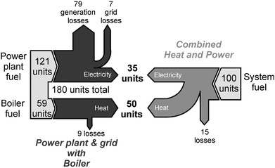 | ||
| Fig. 1 Sankey diagrams showing the advantage of generating heat and power at the point of use. Note that efficiencies are only illustrative and will vary depending on the systems and countries involved. | ||
Condensing boilers provide the highest efficiency gas based heating, which manufacturers claim can be up to 98% efficient. However, SEDBUK (Seasonal Efficiency of Domestic Boilers in the UK)6 laboratory tests show seasonal efficiencies of 91.5% HHV (higher heating value), while independent field trials have demonstrated that real-world efficiency is ∼5% lower than in the laboratory.10
Fig. 2 illustrates the micro-CHP concept applied to a home. Natural gas enters the building from the gas distribution network; the fuel cell (or other co-generation technology) generates heat to service the space and water heating loads and electrical power for lights and other appliances. At times of excess electricity production it can be exported to the grid, and imported at times of high electrical load. Net or ‘smart’ metering allows the balance of export and import to be logged. Similarly, excess production or demand for heat can be accommodated by a hot water storage tank.
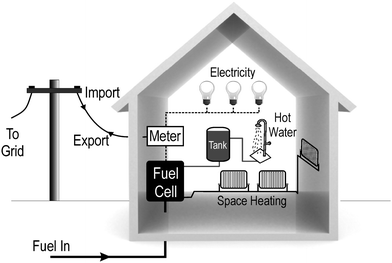 | ||
| Fig. 2 The fuel cell micro-CHP concept showing import/export of electricity. | ||
Operation is also possible in isolated areas with no electrical grid or natural gas distribution network, in which case battery storage may be employed, and fuel would be delivered in cylinders, or stored locally in tanks.7
There is no formal definition of the heat and power range that constitutes ‘micro’ generation. The EU cogeneration directive defines micro-CHP as having ‘a maximum capacity below 50 kW electrical’,8 while Pehnt et al. restrict the definition to a maximum of 15 kWe, which is more suited to single family houses and small businesses.9 The Carbon Trust started their Micro-CHP Accelerator Program by defining micro-CHP as 0–3 kWe, but since added the prefix ‘domestic’ to conform with the EU directive.10
Microgeneration devices are limited to 16 amps per phase if they are to connect to the standard relays used in UK houses, so any devices over ∼3.7 kWe would require a 3-phase ‘G59’ relay—incurring significant installation and line rental costs.11 Such systems are also not intended for district heating, which would require heat distribution networks that are not present in single family houses. Having a thermal output greater than the typical demand from a single house would therefore limit the unit's running hours, and thus its overall benefit. Within the scope of this work, we consider micro-CHP at the residential scale, of the order of ≤3 kWe and ≤20 kWth. Note that the thermal capacity refers to the prime mover only, not any supplementary thermal capacity that many units contain.
The economic case for distributed CHP at the larger scale, appropriate for schools, hospitals, universities, industrial sites, etc., is clear and there is already a thriving industry in this sector. At the residential scale the economic and technological case is less well defined. Whereas commercial micro-CHP is expected to reduce carbon emissions by 15–20%, the Carbon Trust found that potential reductions were marginal for some micro-CHP technologies when installed in domestic housing stock.10
2. Fuel cells for micro-CHP
Fuel cells are electrochemical energy conversion devices that convert chemical energy in fuel directly into electricity (and heat) without involving the process of combustion. A simplistic view of a fuel cell is that it is a cross between a battery (chemical energy converted directly into electrical energy) and a heat engine (a continuously fuelled, air breathing device); this is why fuel cells are sometimes referred to as electrochemical engines. There are a number of fuel cell technologies with very different designs, each suited to different applications. However, they all share the characteristics of high efficiency, no moving parts, quiet operation, and low (compared to heat engines) or zero emissions at the point of use. The range of fuel cell applications and size of the potential markets are enormous, including: battery replacement in small portable electronic devices, prime movers and/or auxiliary power units in vehicles, large scale megawatt (MW) electrical power generation, high-reliability backup power, industrial and micro-CHP. Widespread adoption of fuel cell technology is anticipated to contribute to a reduced dependence on fossil fuels, improve security of electricity supply and lessen CO2 and noxious pollutant emissions.Three of the characteristic differences between the various fuel cell technologies are the diverse sets of materials they are made from, the fuels they can use and their operating temperatures—ranging from ambient to over 1000 °C. Of the technologies currently being deployed, the low temperature polymer electrolyte (PEFC, also known as PEM, PEMFC, SPFC) and high temperature solid oxide fuel cell (SOFC) currently attract the most attention (and development budgets). These two technologies will therefore be the focus of this discussion.
2.1 Fuel cell systems
Fig. 3 shows a generic fuel cell system for residential micro-CHP. The major balance-of-plant (auxiliary components that enable the fuel cell to operate) is shown; however, there are many additional components required for operation such as pressure valves, mass flow controllers, sensors, control system, etc. that are not included. The key issues for each of the main components of the system are now described, starting with the fuel cell itself.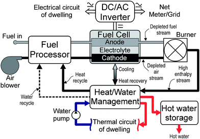 | ||
| Fig. 3 Diagram illustrating the main features of a fuel cell micro-CHP system. | ||
Low temperature fuel cell technologies use precious metal electrocatalysts (e.g.platinum) to ensure adequate electrode reaction kinetics for a high power output. Specialised graphite powders and resins are used, along with the fluorinated polymer electrolytes found in modern chlorine electrolysis cells. High purity hydrogen fuel is required to avoid performance degradation, as the electrocatalysts are easily poisoned by carbon monoxide and other impurities.13 Management of fuel impurities and hydration of the polymer electrolyte requires relatively complex and expensive engineering solutions, and current work is aimed at relaxing these strict requirements by increasing the operating temperature to over 100 °C.14
SOFCs instead use ceramics and specialist chromium alloys or steels that can withstand high temperatures. For micro-CHP applications there is a trend to move from the high temperature region (850–1000 °C) used in early large-scale systems, into the so-called intermediate temperature (IT) range of 500–750 °C.15 This allows a wider range of materials to be used, giving cheaper fabrication and improved resilience to cycling ceramic components between ambient and operating temperatures. Lower temperature operation also affords more rapid start-up and shut-down, reduced corrosion rate of metallic components, more robust construction through the use of compressive seals and metallic interconnects as well as the advantage of greatly simplified system requirements.15
Improved fuel cell performance can be achieved by pressurising the reactant streams, which also aids water management in PEFCs. However, the high parasitic power requirement of a compressor outweighs the benefit in small residential micro-CHP units. These systems typically operate just sufficiently above ambient pressure to ensure the flow control actuators can operate and there is sufficient flow through the system.
If hydrocarbons such as natural gas are to be used as a fuel for low temperature fuel cells, a fuel processor must be used to convert the fuel into hydrogen containing very low levels of carbon monoxide and sulfur. The main difference between PEFC and SOFC systems is in the design of the fuel processor; while PEFCs require high purity hydrogen the SOFC is capable of internally reforming hydrocarbon fuels, reducing the size and cost of the fuel sub-system.
An SOFC fuel processor is typically composed of a desulfuriser and pre-reformer; whereas PEFCs require a larger reformer, and additional shift reactor and gas cleanup stage, all of which add to the cost and complexity, and erode the total system efficiency. The ability of SOFCs to operate at high efficiency on hydrocarbon fuels is a major advantage over low temperature fuel cells, particularly for micro-CHP applications.
Natural gas (or other hydrocarbon fuels) can be converted to hydrogenvia a range of processes, including: steam reforming, partial oxidation and autothermal reforming.16Steam reforming is generally the preferred method as it produces higher concentrations of hydrogen, and thus requires up to 30% less hydrocarbon fuel.17
The hydrogen rich stream leaving the reformer will contain a proportion of CO and sulfurous compounds (usually converted to H2S in the reforming stage) from the fuel source and added odorants. Both of these molecules are poisonous to PEFCs, while SOFCs are able to use CO as a fuel but remain highly sensitive to sulfur.18Sulfur compounds must therefore be removed, usually by reacting with ZnO or adsorption using activated carbon. These units will need to be changed periodically, adding to the maintenance cost of the system. Other desulfurisation techniques exist, but most are not suitable for such small scale applications.16
For PEFCs, the level of CO entering the fuel cell needs to be reduced to the order of <100 ppm in order not to poison the Pt based anode electrocatalyst. The output from the reforming stage contains an appreciable quantity of CO (typically 0.5–3%).19CO produced in the steam reforming process can be converted subsequently to CO2 in a shift reactor, reducing the CO concentration to the order of <1%. Techniques such as selective oxidation of CO and oxygen bleed can be used to reduce the CO concentration to safe levels for the PEFC, at the expense of cost and efficiency, respectively.
The fuel processor for a PEFC is therefore a relatively complicated system, each stage requiring tight temperature control and thermal integration. While this is relatively straightforward for large systems operating at steady state, dynamic operation and the small size of a micro-CHP fuel processor is much more of a challenge. In particular, the turn-down ratio (the minimum sustainable power output relative to the maximum) is compromised since it is difficult to maintain thermal homogeneity due to the relatively large surface-to-volume ratio of smaller units.
SOFC systems have a clear advantage over PEFCs here, since they are capable of fully internally reforming hydrocarbon fuels. Studies have however shown that a small pre-reformer can improve SOFC performance by damping the effects of the strongly endothermic reforming reaction that can lead to excessive thermal stresses in the SOFC stack and shorten the operating lifetime.20
Heat exchanger condensers remove water from the exit of the stack, harvesting heat and supplying process water that can be used for steam reforming or water management of PEFCs. An ion-exchange pack is often used to ensure the purity of the water before feeding it back in the cell, since cation contamination can increase the rate of degradation of membrane electrolytes and certain anions affect the electrocatalysts.
For SOFCs, the cathode air flow is used as the stack coolant, requiring a heavily over-stoichiometric quantity of air (this can be in the range of 3–12 depending on design and operating temperature). The excess air and unconsumed fuel leave the stack at its operating temperature and is combusted in the afterburner; heat from which services the pre-reformer (if present) and pre-heats the reactant streams entering the stack. The excess high-grade heat is available for hot water and space heating. Since the temperature of the exhaust stream (100s of °C) is higher than that of the PEFC cooling circuit (∼80 °C), heat transfer to the thermal circuit of the dwelling is more efficient.
Note that the PEFC can also employ an afterburner and abstract higher temperature heat from unconsumed fuel leaving the fuel cell. As mentioned in the previous section, heat exchangers are usually run in condensing mode, to provide process water and extract more useful heat energy.
The high temperature operation of SOFCs means that the fuel and air entering the stack needs to be pre-heated to a level that avoids thermal shock to the ceramic component of the stack. Therefore, appropriately sized heat exchangers are required to heat the reactant streams and raise steam if a reformer is used.
Silent operation is often cited as a benefit of fuel cells. While it is true that the fuel cell stack operates silently, the blowers, pumps, water evaporation generators, burner, etc. required to operate it will generate a noise level similar to that of a conventional condensing boiler. However, compared to mechanical CHP engines, fuel cell micro-CHP systems should be noticeable quieter; 0–55 dB compared with 95–99 dB.22
For a PEFC, sufficient heat is required to service the endothermic reforming stage of the fuel processor, therefore the stack should operate with a fuel utilisation of no more than ∼70% in order for the unconsumed hydrogen to be burned and service the reformer. Alternatively (or in addition), methane can be burned directly to service the reformer and steam generation.
The control electronics, sensors and actuators all represent a constant parasitic load (e.g. ∼50 W for a Ballard Mk 5 stack), which has a marked impact on system efficiency at low part load and should therefore be minimised for both capital and operating efficiency reasons.
Further information on the different components of fuel cell systems is available in the literature.22,24
3 Fuel cell operation
Fig. 4(a) shows the voltage and power vs. current curve for a generic fuel cell. An increase in current density (current per unit area of each cell) results in a decrease in operating voltage due to internal losses in the system. Power output initially increases and reaches a maximum at point ‘D’. Above which, the decreasing voltage and increasing losses in the system results in loss of electrical power output, although the heat generated continues to increase. The nominal operating point is around point ‘C’, typically ∼⅔ to ¾ of the open circuit voltage of the cell. This point is a trade-off between electrical efficiency and capital cost; for a CHP system, the requirement to service the heat load is also a factor in determining the operating point.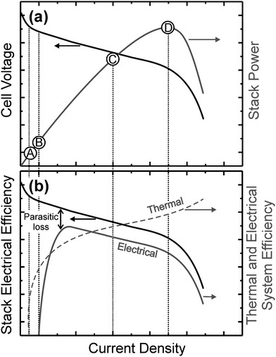 | ||
| Fig. 4 Illustration of the operating range of a fuel cell, showing (a) stack voltage and power and (b) electrical and thermal efficiency. Labelled operation points are described in the text. | ||
Fig. 4(a) represents the steady-state, direct current (DC) output of the stack; however, the dynamic response is also an issue. The speed of response of a fuel cell to a change in electrical load is a function of the electrical capacitance of the stack. Larger cell surface area will have a greater capacitance and therefore take longer to charge/discharge. The electrical response is effectively instantaneous as far as micro-CHP applications are concerned. However, load modulation will change the heat generated by a stack which will affect the electrical performance over a longer time period. A larger stack will have a longer thermal time constant. In addition, there will be a response time lag associated with the mass flow controllers and fuel processor (if present), water management issues may also affect the transient performance. In fact, it is the dynamics of the auxiliary components, particularly the fuel processor, that has the greatest effect on the electrical dynamic response of the system. However, most fuel cell micro-CHP systems will be grid connected, and therefore not required to respond rapidly to changing electricity demand, since the network can accommodate any extreme and fast load changes.
Considering the whole fuel cell system, Fig. 4(b) shows how the electrical and thermal efficiency varies with electrical load. In contrast to heat engines which have a maximum efficiency at their nominal operating point, fuel cells are known to have excellent ‘turn-down’ performance, i.e. reducing the electrical load results in higher electrical efficiency. However, since there are components that require electrical supply (e.g. sensors, actuators, control system), and their load is constant regardless of the power delivered by the fuel cell, this parasitic load degrades the system efficiency at low electrical load. There is a point ‘B’ where the parasitic load equals the power delivered by the fuel cell and the system therefore has ‘zero efficiency’. In a similar sense, for SOFCs there is a lower operational point below which the stack is no longer thermally self-sustaining and begins to cool. There is therefore a practical lower limit below which the system cannot operate. The exact point will depend on the size, shape and materials used to construct the SOFC, but is typically of the order of 20% of the nominal operating point.
It can be seen from Fig. 4(b) that as the electrical load on the fuel cell increases, the thermal efficiency increases and the electrical efficiency decreases. The way in which the heat-to-power ratio of the fuel cell varies with electrical load will depend very much on the system design, but will generally tend to increase when subjected to heavy electrical loading. However, it should be remembered that the heat-to-power ratio of the system can also be controlled at any fuel cell operating point by varying the fuel utilisation and the amount of heat generated in the afterburner.
How a fuel cell micro-CHP unit is sized and operated is a trade-off between system efficiency (fuel cost), unit size (capital cost) and heat-to-power ratio. The rate of performance degradation of the system is also a function of the operating point of the system which will also have an effect on the whole-life economics. Careful techno-economic analysis is required to inform system design and there is great opportunity for advanced system optimisation techniques to be used for this purpose. The subject of fuel cell micro-CHP techno-economic modelling is covered further in section 6.
Sizing of micro-CHP units is complicated by the time (daily and seasonal) variation of electrical and thermal load, as well as potentially varying cost of fuel/electricity and the buy-back rate of electricity exported to the grid.
Fig. 5 shows a representative heat and power load variation over the course of 24 h for a typical family home. Values are in (average) kW, for each 5 min period of a typical winter day. The average heat and electrical load in this example is 3.5 kWth and 0.6 kWe respectively (a heat-to-power ratio of 5.8 : 1). Caccila et al. have reported that an average residential dwelling has an annual heat-to-power ratio of ∼5.5 : 1.26Fig. 6 shows that the electrical power varies by a maximum of ∼3.5 kWe above the average and ∼16 kWth above the heat average, with a maximum heat-to-power ratio of >100.
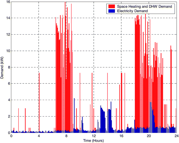 | ||
| Fig. 5 Illustration of a typical electrical and heat load for a UK dwelling. Values are in (average) kW, for each 5 min period of a typical winter day. Based on data from IEA Annex 42.25 | ||
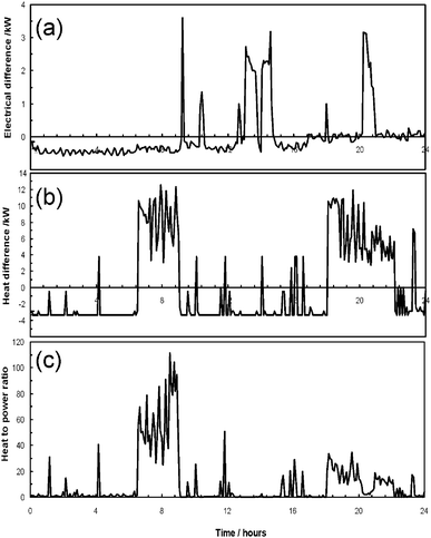 | ||
| Fig. 6 Difference between the average and time varying demands for electrical power (a) and heat (b); with the heat-to-power ratio for a representative single family home (c). | ||
Although the heat-to-power ratio of a micro-CHP system can be varied somewhat by operating at different electrical loads and invoking the use of an auxiliary burner, there are bounds on the range of heat-to-power ratio that can be achieved, outside which the practical time varying heat and power loads exist. Fuel cells have a relatively low heat-to-power ratio (∼0.6–2 : 1) compared with other micro-CHP technologies.
However, it is not the average heat-to-power that is important, but the ability of the unit to meet low heat demands and still be operated at times when there is limited demand for heat, such as summer in Northern Europe. Since electricity is more valuable than heat in terms of CO2 emissions and cost saving, this is a particular advantage for fuel cell technology.
3.1 Performance
Fuel cell performance is often quoted from laboratory scale systems, which do not account for the penalties imposed by fuel processing and other ancillary components. In practice the electrical efficiency of a complete natural gas fired system is one fifth to one third lower than that of the stack alone, due to these parasitic losses. Fuel cell micro-CHP units still offer significantly higher electrical efficiency than engine based technologies, which do not exceed 20% HHV at domestic scale.Japanese field trials have validated the performance of hundreds of PEFC systems, which demonstrated 27–30% efficiency,4,27 compared to rated specifications of around 33% HHV.28 Slightly lower performance is expected in real-world use due to sub-optimal operation, as has been observed with other technologies.10
Smaller trials of SOFC systems based on the Kyocera stack have demonstrated efficiencies ranging from 40–45% HHV when running on natural gas.29,30 Other SOFC designs from American companies typically have 30–35% HHV efficiency.31
Total system efficiencies are generally lower than for engine based CHP systems, averaging around 70–75%.32,33 This is possibly due to the relative immaturity of fuel cell micro-CHP systems, or because PEFC stacks (which dominate the published data sets) produce lower temperature heat which is more difficult to recover. With optimised stack cooling and a condensing heat exchanger, it is believed that the total efficiency could be increased to the levels of engine based CHP and condensing boilers.
As shown in Fig. 4(b), the voltage and stack efficiency increases as the power output of the fuel cell decreases. It is therefore often thought that fuel cells give improved efficiency with the intermittent and often low-level demand from domestic households. However, the sluggish response of the fuel reformer means that fuel utilisation in natural gas fired systems drops sharply as power output decreases. The part-load efficiency of many commercial systems is therefore similar, or slightly lower than their full power efficiency.4,17,34 Improvement of the dynamic response of fuel processors, or some form of buffering would allow the high part-load efficiency of the stack to be harnessed.
The intermittent demand of domestic CHP is also a problem if it requires the fuel cell to be switched on and off several times a day. Currently available SOFC systems are sensitive to thermally cycling between ambient temperature and 700°C+, meaning that warm-up and cool-down cycles take 12–24 h. Most PEFCs also need at least an hour of heating before power can be generated, as their fuel processing units need to be at temperature before operating. The additional energy required during start-up contributes to the lower efficiency seen in field trials.
3.2 Durability
Lifetime and reliability are one of the main hurdles that must be overcome before fuel cells can become commercially viable for micro-CHP.Currently, both PEFC and SOFC stacks lose power at a rate between 0 and 5% per thousand hours, dependant on the design and materials used by each manufacturer.33,35 Reduced catalytic activity in the cells and reformer, combined with increasing cell resistance causes a gradual drop in output voltage, and thus power output. This can shorten stack lifetime, but mechanical deterioration of the cells is usually the limiting factor.
The widely held target for stationary system lifetime is 40,000 operating hours, giving approximately 10 years operation over a typical duty cycle where the unit is operated at regular intervals, but not continuously. Single cell tests have demonstrated this is possible with both PEFC and SOFC under laboratory conditions. Top performing PEFC stacks have demonstrated 20,000 hour lifetimes in field trials,36,48 with 40,000 expected for next-generation systems released in 2009.28SOFC micro-CHP systems have not yet been demonstrated on such a scale, so only limited lifetime data has been reported beyond 5–10 thousand hours of continuous operation.42,37,38
Large scale field trials have revealed that the reliability of micro-CHP systems falls short of expectations, and that the fuel cell stack no longer requires the greatest attention. These complex systems are currently filled with novel and relatively untried components, which has resulted in relatively simple problems causing numerous forced shutdowns. Analysis of nearly 1000 PEFC systems installed in field trials has shown that only 7% experienced no faults in their first year of operation, while each system experienced an average of 2.5–3 failures per year.27 However, the rate of failures almost halved between 2005 and 2007, and manufacturers are confident that they can be reduced to practical levels.
4. Commercial development of fuel cell micro-CHP
Fuel cells have been under development for the past 30 to 50 years, but are still relatively immature in commercial markets. No domestic CHP products are freely available to purchase, and can only be acquired through participation in limited field trials.A recent survey of small stationary fuel cell developers shows that 7000 CHP and backup-power systems under 10 kWe have been installed globally, with over 2000 added in the past year.39 Of these, about 80% have been based on PEFCs, and the remainder were SOFCs.
Japan is leading the way in the domestic CHP market as the government has provided ∼€200 M a year of funding since the turn of the century, catalysing research and commercial demonstration projects.42 This has culminated in the largest public field trial of fuel cell micro-CHP systems, which are to be commercially released in 2009 under the brand name of “ENEFARM”.
The USA has been the largest manufacturer of fuel cell CHP units, but does not have the incentives in place for a local market, so these are mostly exported to Japan. The UK has one large company interested in domestic CHP (Ceres Power), plus a handful of small start-ups and university spin-offs. It is thought that there are only a dozen or so fuel cell CHP units operating in the UK to date, installed as part of public and private field trials.40
Within Europe, two SOFC developers have secured conditional orders from gas suppliers, worth £100–200 million.39 Dutch energy company Nuon have agreed to order 50,000 CFCL units in 2009 if durability targets are met, and Centrica will order 35,000 units from UK based Ceres Power if field trials are deemed successful.39
4.1 Cost
There are no standard prices for domestic CHP units because only R&D and pre-commercial units are available in small volumes. Prices are higher than for other micro-CHP technology in part due to their immaturity, and lie in the range of £10,000–100,000 for a 1 kWe demonstration unit. As production volumes increase, the overhead from research and labour intensive manufacture will be reduced.The most commercially advanced PEFC micro-CHP systems from Japan had an average cost of ∼£24,000 as of 2008, which is expected to fall to £4000–8000 in 5 years time.41SOFC systems are thought to have a similar, but slightly higher price, with early demonstration systems from Hexis and Kyocera costing £32,000 and >£45,000 respectively.31,42 European energy companies have placed bulk orders valued at £3000–5000 per system, with delivery scheduled to begin in 2009.43,44
4.2 Field trials
Real-world demonstrations are growing in importance and number as fuel cells mature into commercially viable products. Since the late 1990s individual manufacturers have held private field trials to test the durability of their evolving designs, prove new components and learn about the practical issues of fuel cell installation. Two of the early pioneering companies to engage in national demonstration programs were Sulzer Hexis and Plug Power.Since 1998 the US Department of Defence funded several demonstration programs of American built fuel cells, providing generous support of up to $100,000 per system.45 Plug Power capitalised on this, winning over 90% of the awarded grants and installing over two hundred of their 5 kWePEFC systems.46 Applications included natural gas fuelled CHP at military bases and residences, and coupling 75 individual units together to form a 375 kWe power station. Detailed results were published by the DoD, showing an outstanding fleet availability of over 90%, but relatively low electrical efficiency due to sub-optimal fuel reformers.47 Lifetime was again identified as a serious obstacle, as most of the fuel cell stacks were changed at least once during the one year trials—with an average lifetime of under five thousand hours.45
Field trials of PEFC systems have rapidly accelerated in Japan, eclipsing all previous projects in terms of installations and funding. Since 2005, over 3300 units from five major Japanese manufacturers have been installed into residential buildings by Japanese gas and oil distribution companies.48 These companies have proven instrumental in the success of the program by providing financial capital, aggressive promotion and a supply of customers as they vie for the first-mover benefit in an emerging market. Results from the trials have been made publicly available by the overseers,27 and are discussed throughout this review.
The largest field trial of small domestic SOFCs was undertaken by Sulzer Hexis between 2001 and 2004, installing over 200 CHP systems in Germany.49 These continued to operate until 2007 and revealed serious problems with the durability of the stacks, which required replacement in as little as six months.31 The company (operating as Hexis) is now trialling four of their improved ‘Galileo’ models, however several failures in auxiliary components have meant that system lifetime is still a major obstacle.37
Demonstrations of SOFC systems are presently around 5 years behind those of PEFCs, and still to date focus on basic technical issues such as materials durability, rather than verifying performance and stimulating mass production. A four year demonstration of Japanese SOFCs began in 2007, led again by gas utilities and the government, who are providing a £4 M annual budget.48 Kyocera is the dominant manufacturer in the region, providing more than three quarters of the 65 systems installed by the end of 2008.50,51
Field trials in Europe remain on a much smaller scale, with 15 and 30 units installed by Baxi Innotech and Vaillant/Plug Power respectively in the last five years.52,53 However, commercial trials by SOFC manufacturers Ceres Power and CFCL are expected to be extended into the region of thousands of units over the next 2–3 years in partnership with European energy companies.54,55
5. Life cycle assessment
While lower CO2 emissions are an important advantage of fuel cell technologies, the magnitude of achievable reductions from the domestic sector remains poorly understood. The majority of published environmental studies consider vehicle propulsion,56 which does not relate well to micro-CHP due to the different design criteria and competing technologies. Of those studies that are relevant, many are obscured due to commercial secrecy, presenting only normalised results or omitting important information.Two aspects of the environmental impact have been studied: the energy and material requirements of producing a fuel cell system, and the CO2reductions that could be achieved by switching from traditional systems to micro-CHP. The former has been estimated with Life Cycle Assessment (LCA), where the processes and materials used to build the system are researched (usually from observing or interviewing a manufacturer), from which a detailed breakdown of the environmental impacts is estimated. These studies conclude that producing a micro-CHP system requires between 2 and 12 GJ of primary energy, and generates 200–600 kg of CO2.57,58 The large ranges are due to different assumptions made by authors, and varied system designs used by manufacturers. SOFC systems are thought to be more energy-intensive to manufacture, due to sintering ceramics at high-temperature and sourcing the materials used for interconnects. However, PEFCs require closed loop recycling to recover the precious metal catalysts and membrane electrolytes in order to minimise their impact.59
Few of these studies go on to consider the subsequent operation of the fuel cell (producing heat and power), and those that do usually over-simplify the process.9 The achievable emissions reductions are therefore estimated in separate studies of fuel cells' operation in buildings. Due to the time and cost of conducting field trials, most authors simulate fuel cells as described in the following section.
Operating data from the demonstration of PEFCs in Japanese homes suggest that annual primary energy demand was reduced by ∼12 GJ (20–25%) and CO2 emissions by ∼1200 kg (30–40%).4,27 High emissions from predominantly coal-fired electricity (690 g kWh−1) allow large CO2reductions to be made by reducing dependence on grid electricity. Simulations relevant to the UK (which has very different demand characteristics when compared with Japan) presented in section 6 suggest that fuel cell micro-CHP could reduce annual domestic CO2 emissions by up to 1.5 tonnes per year (for a household with large demand). This is broadly consistent with previous modelling studies60,61 which predicted reductions of around one tonne per year for a UK-average dwelling.
Results between reports are however not always consistent, with some authors suggesting negligible or even negative impact—with fuel cell micro-CHP producing more CO2 than the technologies it replaces. This variation is due to different assumptions that are made for the efficiency of the fuel cell and the replaced technologies. For example, in the UK, micro-CHP must compete against high efficiency condensing boilers which are not prevalent in Japan. The assumptions made about the carbon intensity of grid electricity is also a crucial factor in estimating environmental benefits.62 The UK building regulations currently recommend that 568 g of CO2 are credited for each kWh of marginal grid electricity generated,63 and 422 g are allocated for each kWh of onsite consumption. However, the government's official long term grid CO2 rate for company reporting is 430 g. Furthermore, this long run average is below the current annual average figure of approximately 550 g.64 These conflicts clearly indicate that there is a great deal of uncertainty regarding appropriate CO2 rates for residential consumption and generation, and this is a ripe area for research. The remainder of this article assumes a grid CO2 rate of 430 g, and it is noted that this choice is the subject of controversy.
Different values for grid carbon intensity also become relevant if other countries are considered, giving a strong geographical dependence to the environment benefit. ‘Greener’ countries such as Brazil and Canada that rely on hydropower would see no benefit from fuel cells so long as they are fuelled by reformed natural gas.
Finally, the CO2 savings from fuel cell micro-CHP will change in the future. Efforts to decarbonise centrally generated electricity with renewables will lessen these benefits when the fuel cell micro-CHP is operating on natural gas—although low efficiency gas and coal are likely to continue generating the marginal (as opposed to constant baseload) electricity that fuel cells displace. Conversely, the potential for fuel cells to be run on renewable biogas or low-carbon ‘green’ hydrogen in the future would allow for even more significant reductions in domestic emissions (potentially up to 100%). Today's gas fired CHP can therefore be seen as an important stepping stone towards a completely renewable and sustainable solution.
6. Techno-economic modelling for fuel cell micro-CHP
The understanding of drivers for commercialisation of fuel cells for residential combined heat and power can be greatly aided by a techno-economic modelling framework. Such a framework can inform the R&D focus of technology developers, and aid choices regarding design and control of the final system. Techno-economic modelling does not just inform fuel cell or stack developers; it also provides insight to OEMs related to balance-of-plant and system integrators, along with commercialisation stakeholders and policy makers, to name a few.The following sections consider the relative merits of two general techno-economic modelling approaches commonly applied to micro-CHP, followed by presentation of some examples of application of a model for systems in the UK context. This leads to practical conclusions regarding what metrics indicate likelihood of good performance, and could form the prerequisites for providing policy support to aid commercialisation.
6.1 Modelling approach: simulation versus optimisation
Techno-economic modelling, by definition, considers the technical characteristics of the system and reflects them onto economic outcomes. It comes in a variety of forms. In general these can be classified as either simulation-based approaches or optimisation-based approaches, each of which has relative strengths and weaknesses. Each specific modelling effort also considers different system boundaries ranging from a component within a fuel cell, through to an entire building and its environment. The following discussion focuses on those approaches that attempt to predict the performance of micro-CHP systems operating in buildings, broken down into simulation and optimisation approaches.Simulation characterises a particular system operating in a specific environment where some characteristic of the system under consideration changes from time period to time period (e.g. power output of the micro-CHP system, temperature inside the building, rates of heat transfer, etc). Various levels of sophistication of simulation exist in the literature, including those that (for example) assume a basic system operating strategy (e.g. follow heat demand), a constant system efficiency, and fixed electricity of thermal demand profiles. More sophisticated models can characterise the dynamics of heat transfer within a building, modelling the interaction between internal spaces and outside, the device itself, and the heat emitters employed. These more sophisticated approaches are usually termed building simulation models, and more examples that incorporate micro-CHP are becoming available (e.g. ESP-r, EnergyPlus, TRANSYS). The primary strength of simulation-based approaches is that they can characterise change in a large number of (potentially highly non-linear and intricately interrelated) parameters changing from time period to time period. This means they can produce more accurate estimates of energy consumption, etc. for a given system in a specific building.
Whilst simulation-based approaches certainly have some advantages, they are more challenged to provide understanding of emerging technology where system design and operational parameters remain ill-defined. Optimisation-based approaches have relative strengths in this regard. This is because unit commitment optimisation† can reflect a system's technical constraints back onto its operating strategy. Therefore, while a technology is in the design, development and integration stages, optimisation is a useful tool to investigate the relative benefits of particular characteristics of the technology. If changing a particular technical characteristic results in a better operating strategy becoming available, the unit commitment optimisation will immediately identify this (for example, this technique could be used to investigate the relationship between performance of the fuel cell and its ability to rapidly respond to load changes). The technology developer may then choose to devote research and development time to providing a product with that technical characteristic, and enable the associated operating strategy. Simulation could produce equivalent results, but usually only by “brute force” methods where a simulation is run many thousands of times to investigate sensitivities. Additionally, the relative advantage of simulation (that it can provide better representation of system dynamics) can be partially offset by optimisation constraints, which when properly formulated can emulate system dynamics from stack level through to building level.
Overall, simulation is a useful tool for accurately assessing the performance of energy systems in the built environment, whilst optimisation is arguably more useful for informing technology development. Because fuel cell micro-CHP is the subject of research and development (i.e. no significant examples of its commercialisation yet exist), techno-economic unit commitment optimisation is the authors' preferred method for examining its credentials. The following section presents some selected results from techno-economic modelling for micro-CHP.
6.2 Selected results from techno-economic modelling
An optimisation-based techno-economic modelling framework has been developed by Hawkes et al.65 This framework minimises the operating cost for a defined micro-CHP system meeting a given electrical and thermal energy demand profile, noting here that we do not distinguish between the different temporal thermal demand for hot water or space heating, but consider only total thermal demand. Thermal and electrical demand profiles are sourced from Knight et al.,66 and HM Government,67 and are assumed to represent a cross-section of UK dwelling construction types (i.e. from low to high energy demand; flat, bungalow, terrace, semi-detached, and detached dwellings). The primary economic metric optimised by this model is the maximum allowable cost difference between the micro-CHP system and the competing reference boiler system. This is calculated assuming a 12% cost of capital, broadly reflecting an acceptable commercial rate. Therefore this represents the situation where an Energy Service Company (ESCo) purchases the equipment and recoups that expenditure by (for example) charging the dwelling occupier for provision of their energy services each year. Further details and examples of applications of the modelling framework can be found in the literature.61,68,69 Demand and system response is modelled at 5 min temporal resolution, which avoids substantial errors associated with coarser resolutions.70The following two subsections present examples of how this framework can be applied to examine important characteristics of micro-CHP products. The reader should note that there are a large number of potential technical characteristics that can be investigated using techno-economic analysis, and only a selected few are presented here.
Four micro-CHP technologies (SOFC and PEFC-based fuel cells, internal combustion engines (ICEs), and Stirling engines) are investigated in order to provide context of the relative performance of the fuel cell-based systems with respect to their competitors. Basic technical parameters of each technology are presented in Table 1, and each system is assumed to have a 10 y lifetime (i.e. medium-term technology for fuel cell-based systems).
| Internal combustion engine | PEFC | SOFC | Stirling engine | |
|---|---|---|---|---|
| a The higher operating temperature of SOFCs mean they would be expected to display greater overall efficiency than a PEMFC system, but the results reported to date in published trials do not reflect this due to high thermal losses from the systems tested. With optimum engineering design, the overall efficiency an SOFC m-CHP would be expected to be 85–90%. All analysis reported in this paper is based on the published data shown in Table 1. | ||||
| Electrical efficiency (part load, full load) | 10%, 20% | 30%, 26% | 45%, 40% | 5%, 10% |
| Overall efficiency (part load, full load) | 80%, 85% | 80%, 85% | 75%, 80%a | 80%, 90% |
| Supplementary thermal system efficiency | 86% | 86% | 86% | 86% |
| Minimum operating set point (% of rated power) | 20% | 20% | 20% | 20% |
| Minimum up-time (min) | 10 | 60 | 60 | 10 |
| Maximum ramp rate (kWe min−1) | 0.2 | 0.2 | 0.05 | 0.2 |
| Start-up energy consumption (kWe, kWth) | 0.008, 0.5 | 0.017, 1.6 | 0.017, 2.0 | 0.008, 0.5 |
A defensible choice of the reference system to which micro-CHP is compared is also an important consideration when assessing performance. In this study the baseline reference system is the case where thermal demands are met by a highly-efficient condensing boiler, and electricity demands are met by grid-average electricity. As discussed in section 5, these choices are the subject of significant and justified controversy because of the way micro-CHP might interact with the existing conventional energy system. Further (and conflicting) analysis of these issues can be found in Voorspools et al.73 and Bettle et al.,74 but for the analysis below the reference system is assumed to consist of grid electricity (at 10.25 pence kWh−1, and 0.43 kg CO2kWh−1), and natural gas (at 2.45 pence kWh−1, 0.19 kg CO2kWh−1) combusted in a condensing boiler.
6.3 Capacity choice
Choice of prime mover rated capacity is an important concern for fuel cell micro-CHP systems developers in terms of where their product fits into the market, and those concerned with assessing the potential of micro-CHP in the market. This is important because examination of a single capacity system may miss valuable opportunities for micro-CHP developers to scale-up or scale-down their products.The first point to note with regard to Fig. 7 is the considerable variation in the value of micro-CHP technologies with respect to competing conventional boiler systems. For 1 kWefuel cell-based systems operating in a mean demand situation (i.e. the Terrace house) a rational investor with 12% cost of capital would pay between £700 and £800 more than the cost of the competing boiler. Conversely, a rational investor would only pay approximately an extra £200 for the modelled Stirling engine system. One cannot draw conclusions regarding comparison between the economic attractiveness of the technologies based on this result because manufacturing and installation costs for systems incorporating each prime mover type are not yet readily observable, but it is clear that fuel cell system developers have more room to move on cost.
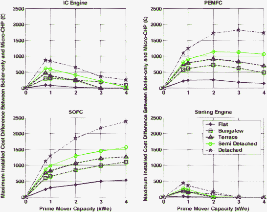 | ||
| Fig. 7 Economic case for four fuel micro-CHP technologies with respect to prime mover generating capacity (kWe) and dwelling construction type. The maximum installed cost difference is the maximum extra cost that a rational investor would pay compared to the cost of the competing boiler. | ||
The second point to note with regard to Fig. 7 is the value per kWe installed for each technology. This relates to the slope of the lines in each subplot (i.e. the first derivative of the curves). All lines have the largest positive gradient between 0 kWe and 1 kWe prime mover capacity. As prime mover capacity increases thereafter, value per kWe installed decreases. This suggests that it is questionable to provide a product to the UK single residence dwelling market with prime mover capacity greater than 1 kWe. This result does vary between technologies; the value per kWe installed for fuel cell-based systems is not as sensitive to increasing capacity as the engine-based systems. Indeed a very large 4 kWeSOFC-based system has a marginal value of almost £2500, which is possibly an economic manufacturing proposition if economies of scale entail cheaper production (per kWe) of larger systems. Regardless of such possibilities, micro-CHP systems with 1 kWe electricity generating capacity present the highest value per kWe installed, and are arguably the best proposition for the UK market which is dominated by single-residence dwellings, and does not have widely available heat distribution networks.
The final point regarding Fig. 7 is the variation of economic result between the building variants. Clearly, the larger the energy demands in the building, the better the case for investment in micro-CHP. This result is apparent across technologies.
6.4 Annual energy demand and prime mover heat-to-power ratio
It has been widely reported that there is a relationship between the thermal demand met by CHP units and their economic viability, with consistent thermal demand often associated with positive results.10 Whilst it is not expected that micro-CHP is an exception to this rule, it is informative to investigate the extent to which annual demand influences the value of micro-CHP, given the unique nature of residential tariffs and demand.Inspection of Fig. 8 reveals that the dependence of the economic result on annual thermal demand is evident in all cases, but is more obvious in the cases of micro-CHP systems with higher heat-to-power ratios (i.e. the IC engine and the Stirling engine). The IC engine and Stirling engine benefit most from increasing thermal demand, and both fuel cell-based systems show weaker improvement of economic result as annual thermal demand increases. SOFC-based systems are the most economically-resilient to changes in annual thermal demand.
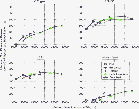 | ||
| Fig. 8 Sensitivity of economic performance of four micro-CHP systems to annual thermal demand with 1 kWe micro-CHP systems. | ||
Fig. 9 displays the sensitivity of the economic result to annual electricity demand (plotted across three cases of annual thermal demand; low (existing flat), average (existing terrace), and high (existing detached house)). It is apparent from Fig. 9 that the economic results of both fuel cell-based systems show strong dependence on annual electricity demand; much stronger than their sensitivity with respect to annual thermal demand observed in Fig. 8. Conversely, the two engine-based systems show approximately the same sensitivity to annual thermal demand as they do to annual electricity demand. It can be deduced that electricity demand and thermal demand are both important for a positive economic result for the engine-based systems, but electricity demand is the primary driving factor for economic performance of the fuel cell-based systems.
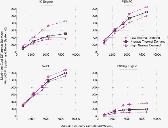 | ||
| Fig. 9 Sensitivity of economic performance to annual electricity demand with 1 kWe micro-CHP systems. | ||
The combination of Fig. 8 and Fig. 9 can be interpreted as follows: Those systems that produce more heat are more likely to be more influenced by the level of annual thermal demand. Lack of thermal demand, or significant heat production for a given electricity output (i.e. a high heat-to-power ratio), corresponds to a constraint on system operation. Essentially these thermal issues limit a system's ability to benefit from displacing onsite electricity demand. Conversely, the economics of systems that produce less heat (i.e. low heat-to-power ratio) is strongly driven by annual electricity demand. This relates to the fact that thermal constraints do not interfere so much in their operation, and they can therefore access the value associated with generating electricity to displace onsite demand (which would otherwise have been met by more expensive grid electricity). Lack of onsite electricity demand obviously limits the ability of the system to displace it. In summary, low thermal demand or excessive heat production are constraints for micro-CHP that prevent systems generating electricity and achieving corresponding value creation. Primary value lies in generating electricity to displace onsite demand; access to this value is enabled by the presence of thermal demand (and onsite electrical demand) and/or application of a micro-CHP prime mover with a low heat-to-power ratio—such as fuel cells.
It is also instructive to consider the sensitivity of the CO2 result to annual thermal demand (holding electricity demand constant), and annual electricity demand (holding thermal demand constant). Fig. 10 and 11 present these sensitivities for the four 1 kWe micro-CHP systems.
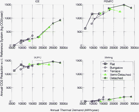 | ||
| Fig. 10 Sensitivity of annual CO2reduction with respect to reference system (kg CO2 year−1) to annual thermal demand for five annual electricity demand scenarios with 1 kWe micro-CHP systems. | ||
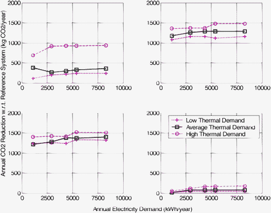 | ||
| Fig. 11 Sensitivity of annual CO2reduction with respect to reference system (kg CO2 year−1) to annual electricity demand for three annual thermal demand scenarios with 1 kWe micro-CHP systems. | ||
Fig. 10 shows that annual thermal demand can be important in micro-CHP achieving CO2reductions. This is particularly apparent for the mid-range heat-to-power ratio (HPR) ICE and PEFC-based systems. The Stirling engine has difficulty producing noteworthy emissions reduction for any annual thermal demand scenario, and the SOFC-based system provides reductions largely independent of annual thermal demand. These two extreme cases (i.e. the Stirling and SOFC systems) relate once again to heat-to-power ratio (HRP); the Stirling engine (high HPR) is unable to provide reductions because its operation is frequently curtailed by thermal constraints, whilst the SOFC-based prime mover (low HPR) can operate almost all the time because it rarely encounters these constraints. Mid-range HPR systems are more sensitive because as thermal demand increases, thermal constraints bear less upon systems ability to operate and thus reap associated CO2reductions.
Fig. 11 shows the CO2reduction achievable by 1 kWe micro-CHP systems across a range of annual electricity demand scenarios (each line represents constant annual thermal demand). This figure shows little reliance of CO2reduction on annual electricity demand. This can be contrasted with the equivalent economic result presented in Fig. 9, which showed strong dependence of economic result on annual electricity demand for low heat-to-power ratio prime movers. The reason for this contrasting CO2 result is that displaced grid electricity CO2 rates are the same regardless of whether generation is consumed onsite or exported to the grid (conversely, in the economic case, export attracts a lower value than onsite generation).
6.5 Key performance metrics
Based on the results presented above, it is possible to draw some broad conclusions regarding metrics that are crucial in determining the likely performance of a micro-CHP system. The economic results suggest that heat-to-power ratio of the micro-CHP prime mover (i.e. the fuel cell stack), the rated thermal capacity (kWth) of the prime mover, and the annual thermal and electrical demand of the target dwelling. Essentially thermal constraints serve to limit the ability of the system to operate, whilst electrical demand furnishes access to additional value through its displacement. The environmental results largely reflect this outcome, with one notable exception; onsite electrical demand is not so relevant to CO2-related performance. This occurs because there is no differentiation (in terms of CO2reduction) between onsite generation that is consumed onsite or exported to the grid.From a public policy point of view, which is partly concerned with CO2reduction, the primary differentiations between micro-CHP technologies relates to their;
• Heat-to-power ratio, with low values indicating better performance.
• Rated thermal output, which also relates to thermal constraints.
• The annual thermal demand of the target dwelling, with higher demands indicating higher performance. However, low heat-to-power ratio prime mover performance is less influenced by this factor.
As suggested in Hawkes and Leach,75 these three parameters (along with system accreditation to ensure high overall efficiency) could be used as a basis for providing government support for commercialisation of micro-CHP. Clearly fuel cell-based micro-CHP would be well placed to benefit from such support.
7. Conclusions
Fuel cells offer a promising technology for micro-CHP applications, though it has yet to reach full commercialisation. Here, we have examined issues related to the technology and its mode of operation, and reviewed the current state of commercialisation and field trial activity. This was followed by comment on the life cycle assessment CO2 performance and presentation of methods and results from a techno-economic modelling approach which has been formulated to aid design and control decisions.This article has demonstrated that the key economic driver for micro-CHP is the ability to meet onsite electricity demand. This ability is influenced by (a) the presence of onsite electricity demand and (b) thermal constraints. The thermal constraints relate to the fact that the micro-CHP system cannot operate when there is insufficient thermal demand, thereby limiting the ability of the system to meet onsite electricity demand. Therefore, the presence of significant thermal demand is important, as is the development of fuel cell micro-CHP systems with a very low heat-to-power ratio. Fuel cells have a relative advantage over other micro-CHP technologies in this regard in that their high electricity efficiency implies they are more likely to achieve a low heat-to-power ratio if appropriately designed.
Drivers for environmental performance of fuel cell micro-CHP were found to be almost identical to the economic drivers. The only distinction is that onsite electricity demand is not important for CO2reduction, because credit for displaced CO2 exists regardless of whether the electricity is consumed onsite or exported to the grid. However, it has been noted that CO2reduction is heavily dependent on the appropriate credit rate for generated electricity, and predicted rapid decarbonisation of grid electricity could lead to reduced carbon saving in some circumstances. However, this issue requires further investigation, in particular of future trends in the use of lower carbon gas grids, before defensible conclusions can be drawn.
Finally, for fuel cell micro-CHP to be successful, it is essential that we overcome the key technical challenges of improving the dynamic efficiency and durability of operating systems, as well as lowering the capital cost of systems.
Acknowledgements
The authors would like to acknowledge the United Kingdom Energy Research Centre (UKERC) for funding the activities of the Microgeneration Group.References
- IPCC, Climate Change 2007. The Physical Science Basis Contribution of Working Group I to the Fourth Assessment Report of the IPCC, 2007 Search PubMed.
- HM Government, Climate Change Act 2008, The Stationary Office, London, UK, 2008 Search PubMed.
- Energy Saving Trust. Delivering the Government's 2020 vision for local energy generation. Energy Saving Trust, London, 2005 Search PubMed.
- Y. Yamada, Performance of Residential FC CHP LIFUEL in actual and daily use for years. Presented at Tenth Grove Fuel Cell Symposium, London, 2007 Search PubMed.
- N. Bergman, A. Hawkes, D. J. L. Brett, P. Baker, J. Barton, R. Blanchard, N. P. Brandon, D. Infield, C. Jardine, N. Kelly, M. Leach, M. Matian, A. D. Peacock, I. Staffell, S. Sudtharalingam and B. Woodman. Proceedings of ICE: Energy, in press Search PubMed.
- http://www.sedbuk.com/ last accessed 12/1/09.
- S. Jiro, N. Kojiro, N. Yasuhiro, S. Hirofumi, I. Yozo, Y. Masanori and K. Noriko, Trans. Inst. Electr. Eng. Jpn., B, 2007, 127, 145 Search PubMed.
- Directive 2004/8/EC of the European Parliament and of the Council of 11 February 2004 on the promotion of cogeneration based on useful heat demand in the internal energy market and amending Directive 92/42/EE. European Union, Bruxelles. 2004 Search PubMed.
- M. Pehnt, M. Cames, C. Fischer, B. Praetorius, L. Schneider, K. Schumacherand J.-P. Voß, Micro Cogeneration Towards Decentralised Energy Systems, Springer, Netherlands, 2006 Search PubMed.
- Carbon Trust, Micro-CHP Accelerator: Interim Report. Carbon Trust, London, 2007 Search PubMed.
- Swift Turbines Ltd. Rooftop Wind Energy System: Technical and Planning Information. June 2005 Search PubMed.
- D. J. L. Brett and N. P. Brandon, J. Fuel Cell Sci. Technol., 2007, 4, 29 CrossRef CAS.
- J. J. Baschuk and X. G. Li, Int. J. Energy Res., 2001, 25, 695 CrossRef CAS.
- J. Zhang, Z. Xie, J. Zhang, Y. Tang, C. Song, T. Navessin, Z. Shi, D. Song, H. Wang, D. P. Wilkinson, Z.-S. Liu and S. Holdcroft, J. Power Sources, 2006, 160, 872 CrossRef CAS.
- D. J. L. Brett, A. Atkinson, N. P. Brandon and S. Skinner, Chem. Soc. Rev., 2008, 37, 1568 RSC.
- G. Kolb, Fuel Processing for Fuel Cells, Wiley, 2008 Search PubMed.
- C.-E. Hubert, P. Achard and R. Metkemeijer, J. Power Sources, 2006, 156, 64 CrossRef CAS.
- P. Lohsoontorn, D. J. L. Brett and N. P. Brandon, J. Power Sources, 2008, 183, 232 CrossRef CAS; P. Lohsoontorn, D. J. L. Brett and N. P. Brandon, J. Power Sources, 2008, 175, 60 CrossRef CAS.
- D. J. L. Brett, P. Aguiar, N. P. Brandon and A. Kucernak, Int. J. Hydrogen Energy, 2007, 32, 863 CrossRef CAS.
- P. Aguiar, C. S. Adjiman and N. P. Brandon, J. Power Sources, 2004, 138, 120 CrossRef CAS.
- D. S. Schmidt. Status of the Acumentrics SOFC Program. Fuel Cell Seminar, Honolulu, 2006 Search PubMed.
- J. Garche and L. Jörissen, in Handbook of Fuel Cells – Fundamentals, Technology and Applications, ed. W. Vielstich, H. A. Gasteiger and A. Lamm, John Wiley & Sons. 2003, vol. 4 Search PubMed.
- W. Colella, J. Power Sources, 2002, 106, 388 CrossRef CAS.
- L. J. M. J. Blomen and M. N. Mugerwa, Fuel Cell Syst., Springer, 1994 Search PubMed.
- International Energy Agency (IEA), Annex 42-detailed load profiles, www.cogen-sim.net/ (last accessed 06/04/09).
- G. Cacciola, V. Antonucci and S. Freni, J. Power Sources, 2001, 100, 67 CrossRef CAS.
- Report data from the Large Scale Residential Fuel Cell Demonstration Project in 2007, New Energy Foundation, 2008, p. 36, (in Japanese).
- Panasonic. Panasonic Develops New Fuel Cell Cogeneration System for Home Use. Press release dated 14th April, 2008. http://panasonic.co.jp/corp/news/official.data/data.dir/en080414-2/en080414-2.html Search PubMed.
- Kyocera Corporation. Osaka Gas and Kyocera Announce the Results of the First Domestic Trial Operations of Solid Oxide Fuel Cell (SOFC) Cogeneration System for Household Use. Press release dated 16th May, 2006. http://global.kyocera.com/news/2004.1202.html Search PubMed.
- T. Homma. The Latest Fuel Cell News in Japan, July 2006. http://www.fcdic.com/eng/news/200607.html#2 Search PubMed.
- S. C. Singhal, Innovative Solid Oxide Fuel Cell Systems for Small Scale Power Generation. Presented at Tenth Grove Fuel Cell Symposium, London, UK, 2007 Search PubMed.
- I. Staffell, Review of PEM Fuel Cell Performance, Nov. 2007 Search PubMed.
- I. Staffell, Review of Solid Oxide Fuel Cell Performance, Nov. 2007 Search PubMed.
- T. Inagaki, F. Nishiwaki, S. Yamasaki, T. Akbay and K. Hosoi, J. Power Sources, 2008, 181(2), 274–280 CrossRef CAS.
- F. A. de Bruijn, V. A. T. Dam and G. J. M. Janssen., Fuel Cells, 2008, 8, 3 CrossRef CAS.
- T. Homma. The Latest Fuel Cell News in Japan, June 2008 Search PubMed.
- A. Mai, Fuel Cell Seminar, San Antonio, Texas, 2007 Search PubMed.
- Acumentrics, Acumentrics Fuel Cell Tops 10,000 Operating Hours. Press release dated 8th September, 2008. http://www.acumentrics.com/15761fb4-8896-452d-adf3-15a94c7119c4/press-releases-release-details.htm Search PubMed.
- K.-A. Adamson. Fuel Cell Today Small Stationary Survey. 2008 Search PubMed.
- Micropower Council, Micropower in the UK - State of the Nation and Remaining Challeges, 2007.
- I. Staffell and R. Green, Estimating future prices for stationary fuel cells with empirically derived experience curves, Int. J. Hydrogen Energy, submitted Search PubMed.
- A. Yamamoto, Fuel Cell Seminar & Exposition, Phoenix, Arizona, 2008 Search PubMed.
- http://www.ceramics.org/ASSETS/F9B18F109B3A4927B5823B00B6D%20CDB75/CERAMICSEnergy_0408.pdf, last accessed 12/1/09.
- http://www.fcdic.com/eng/news/200706.html, last accessed 12/1/09.
- M. K. White, DOD Residential Proton Exchange Membrane (PEM) Fuel Cell Demonstration Program: Volume 2 – Summary of Fiscal Years 2001–2003 Projects. 2005 Search PubMed.
- ERDC-CERL Fuel Cell. DoDFuelCell EDRC/CERL Projects. 2008.
- ERDC-CERL Fuel Cell. Site Performance Summary Table. 2008.
- K. Nishizaki. Gas Industry Micro CHP Workshop, Paris, 2008 Search PubMed.
- Intelligent Energy, Review of Technical, Socio-Economic and Safety Findings from Stationary Fuel Cell Demonstration Activities. Roads2HyCom, 2007 Search PubMed.
- T. Homma. The Latest Fuel Cell News in Japan, May 2008 Search PubMed.
- T. Homma. The Latest Fuel Cell News in Japan, February 2008 Search PubMed.
- Baxi Innotech, Report on field trials, Fuel Cells Bull., 2007, 5, 8 Search PubMed.
- Vaillant, Fuel Cells Bull., 2004, 4, 2.
- Reuters. Ceres Power Holdings - New British Gas CHP agreement. Press release dated 14th January, 2008. http://www.reuters.com/article/pressRelease/idUS49778+14-Jan-2008+RNS20080114 Search PubMed.
- B. Bilton. Ceramic Fuel Cells Limited: Company Overview. Gas Industry Micro CHP Workshop, Paris, 2008 Search PubMed.
- T. Geerken, V. Timmermans, and S. Lassaux, Hydrogen and its Applications: Review of Life Cycle Assessment Studies and Well-to-Wheel Studies. Hysociety, 2005 Search PubMed.
- V. Karakoussis, N. P. Brandon, M. Leach and R. van der Vorst, J. Power Sources, 2001, 101, 10 CrossRef CAS.
- M. Pehnt, Dissertation, Institut für Technische Thermodynamik, Universität Stuttgart, 2001 Search PubMed.
- M. Pehnt, in Handbook of Fuel Cells – Fundamentals, Technology and Applications, ed. W. Vielstich, A. Lamm, and H. A. Gasteiger, John Wiley & Sons: Chichester, 2003, vol. 4, ch. 13 Search PubMed.
- A. D. Peacock and M. Newborough, Appl. Therm. Eng., 2005, 25, 2653 CrossRef.
- A. D. Hawkes and M. A. Leach, Energy, 2007, 32, 711 CrossRef.
- J. Cockroft and N. Kelly, Energy Convers. Manage., 2006, 47, 2349 CrossRef.
- Standard Assessment Procedure for Energy Rating of Dwellings (SAP) 2005. http://www.bre.co.uk/sap2005, last accessed 12/1/09.
- BERR, Digest of UK Energy Statistics 2008. TSO, London, 2008 Search PubMed.
- A. D. Hawkes, P. Aguiar, C. A. Hernandez-Aramburo, M. A. Leach, N. P. Brandon, T. C. Green and C. S. Adjiman, J. Power Sources, 2006, 156, p. 321 Search PubMed.
- I. Knight, N. Kreutzer, M. Manning, M. Swinton and H. Ribberink,, European and Canadian Non-HVAC Electric and DHW Load Profiles for use in Simulating the Performance of Residential Cogeneration Systems. IEA ECBCS Annex 42 on Residential Cogeneration, Cardiff, UK, 2007 Search PubMed.
- H. M. Government, Domestic Photovoltaic Field Trials: Final Technical Report. DTI, London, UK, 2006 Search PubMed.
- A. Hawkes and M. Leach, J. Power Sources, 2005, 149, 72 CrossRef CAS.
- A. D. Hawkes, P. Aguiar, B. Croxford, M. A. Leach, C. S. Adjiman and N. P. Brandon, J. Power Sources, 2007, 164, 260 CrossRef CAS.
- A. D. Hawkes and M. Leach, Energy, 2005, 30, 1759 CrossRef CAS.
- U. Arndt, I. Beausoleil-Morrison, M. Davis, W. D'haeseleer, V. Dorer, E. Entchev, A. Ferguson, J. Gusdorf,N. Kelly, M. Manning, L. Peeters, M. Sasso, D. Schreiber, S. Sibilio, K. Siemens, and M. Swinton,, Experimental Investigation of Residential Cogeneration Devices and Calibration of Annex 42 Models., 2007. http://www.cogen-sim.net Search PubMed.
- C. Wallmark and P. Alvfors, J. Power Sources, 2003, 118, 358 CrossRef CAS.
- K. Voorspools, P. Voets, and W. D'Haeseleer,. International Conference on Power Generation and Sustainable Development. Liege, 2001 Search PubMed.
- R. Bettle, C. H. Pout and E. R. Hitchin, Energy Policy, 2006, 34, 3434 CrossRef.
- A. D. Hawkes and M. A. Leach, Energy Policy, 2008, 36(8), 2963.
Footnote |
| † The reader should note that optimisation-based approaches relating to system design such as pinch technology (pinch technology is formulated to maximise system thermal efficiency, regardless of economic outcome) do not use a unit commitment approach. They are not considered in this article. |
| This journal is © The Royal Society of Chemistry 2009 |
