Electrochemical performance of a hybrid direct carbon fuel cell powered by pyrolysed MDF
Sneh L.
Jain
a,
J.
Barry Lakeman
b,
Kevin D.
Pointon
*b,
R.
Marshall
c and
John T. S.
Irvine
*a
aSchool of Chemistry, University of St Andrews, St Andrews, KY16 9ST, UK. E-mail: jtsi@st-and.ac.uk
bDstl Porton Down, Salisbury, Wilts, SP4 0QR, UK. E-mail: KDPOINTON@mail.dstl.gov.uk
cMicro Power Energy (Scotland) Ltd, Glasgow, G5 8TA
First published on 2nd March 2009
Abstract
Medium density fibreboard is a ubiquitous element in modern furniture, here we consider utilising waste MDF as a future energy source. In particular, we focus upon the hybrid direct carbon fuel cell (HDCFC), which involves a combined molten carbonate/solid oxide fuel cell anode/electrolyte interface and can be fuelled by a wide range of carbon forms. Current–voltage measurements and a.c. impedance at temperatures in the range of 525–800 °C have been made on cells powered by pyrolysed medium density fibreboard (pMDF) samples which had undergone three different preparatory treatments (immersion of strips in molten eutectic carbonate mixture; deep soaking of strips in aqueous carbonate mixture corresponding to the eutectic composition and fine powdering). Below 700 °C the three pMDF samples show quite different electrochemical performance in the HDCFC, but above 700 °C their behaviour becomes similar. Powdered pMDF gives the best OCV (0.89 V) and lowest resistance (2.36 Ω) values below 700 °C, although the electrochemical performance is dominated by diffusion limitations and the performance degrades at higher temperatures. The immersed strip behaves quite differently with limited performance below 750 °C but it shows both good OCV, 1 V, and low resistance, <4 Ω, at higher temperatures. Three components are discernable, an ohmic contribution probably due to both ionic resistance of zirconia electrolyte and electronic resistance of current collection and two electrode processes thought to be associated with the transfer of oxygen ions at the electrode : electrolyte interface and diffusion of reactant species through the electrode. The activation energies calculated from the ohmic resistances for the three samples (−0.79 – −1.00 eV) are of similar order to that expected for the yttria zirconia electrolyte.
Broader contextCarbon is an attractive fuel due to its high energy density; however thermal conversion systems are normally inefficient and produce a lot of carbon dioxide mixed with nitrogen. Direct carbon fuel cells (DCFCs) offer high efficiency, and hence lower carbon dioxide outputs. Furthermore the exhaust gases are not diluted with nitrogen and hence are easier to sequester. Medium density fibreboard, MDF, is widely used in modern living and there ample sources of waste MDF available. Here the oxidation of pyrolysed samples of MDF in a DCFC is investigated. The DCFC used involves a hybrid anode utilising a molten carbonate electrode to extend the anode away from the solid oxide electrolyte interface. Pyrolysed MDF has proven to be a very good fuel for the hybrid DCFC system yielding powers as high as 50 mW and open circuit voltages of 1 V. |
Introduction
The world's dwindling fossil fuel reserves and the ever-growing demand for affordable and efficient power sources have driven intensive research activity worldwide into new power generation technologies.1 One technology with great potential from several standpoints is the fuel cell. Hydrogen-powered fuel cells have, to date, received widest attention but other competing technologies exist, including the direct carbon fuel cell (DCFC). In DCFCs, the electrochemical oxidation of carbon fuel proceeds with the formation of CO2 and the generation of electrical energy.2 Although a prototype DCFC based on a molten sodium hydroxide electrolyte was demonstrated in 1896,3 there was little further development for several decades. DCFC research has undergone a recent renaissance for several important reasons. The volumetric energy released upon the electrochemical oxidation of carbon by O2 (23.95 kWh l−1) exceeds that of most common fuels (e.g. hydrogen, methane, diesel)4 and, critically, very high theoretical efficiencies are achievable if complete oxidation to CO2 occurs. Carbon is available from many sources (for example coal, via pyrolytic processing of biomass or plastics, hydrocarbon cracking) and sequestration of CO2 streams from DCFCs is attractive as the CO2 evolved is not diluted with nitrogen from air in a DCFC fuel cell anode.Several conceptual variants of DCFC are known, and many features are common throughout. In order for the anodic oxidation of carbon to proceed quickly enough to produce electricity efficiently, a high operating temperature is needed, consequently many designs utilise molten salts (alkali metal carbonates or alkali metal hydroxides)5–7 as the electrolyte or liquid metal (specifically, tin).8 Significant advances have been made with molten carbonate versions of the DCFC in particular.9 Corrosion and electrolyte distribution problems are inherent with many designs, and hydroxide electrolytes are prone to carbonate formation. Other very recent advents in DCFC designs make use of aqueous solutions of alkali metal hydroxides10 or a fluidised bed of CO2.11 Dependent upon the cell architecture, a wide range of carbon variants can be used to power the cells, including coal, plastics, coke or charcoals.
The hybrid DCFC (HDCFC) merges solid oxide and molten carbonate fuel cell technologies and employs a 62 : 38 mol% eutectic mixture of Li2CO3–K2CO3.12–14 Readily available materials such as yttria stabilised zirconia (YSZ), lanthanum strontium manganate (LSM) and NiO are used to construct the HDCFC. The cathode is protected from corrosion as it is not in contact with the eutectic carbonate. The HDCFC can operate with a wide range of carbons, including coal, high surface area carbons and pyrolysed biomass, and exhibits good current–voltage performance in the 525–800 °C temperature range. The electrochemistry of the direct oxidation of solid carbon in the HDCFC with solid oxide and molten carbonate binary electrolyte was recently investigated using a planar test cell.15 The carbon/carbonate slurry increased the active reaction zone from a two-dimensional Ni/YSZ anode to a three-dimensional slurry and significantly enhanced carbon oxidation. The planar HDCFC showed quite high open circuit voltage (OCV) compared to tubular mainly because of better sealing and purging of gases in the planar set up. O2− and CO32− were suggested to be the main active species for the electrochemical oxidation of solid carbon in the carbon/carbonate slurry. The electrochemical oxidation in the anode compartment is quite selective to CO2 formation, but the final distribution of products is dominated by the equilibrium of the Boudouard reaction, which increasingly yields CO as temperature increases.
As part of our research into new carbon feedstocks for use in HDCFC we have investigated pyrolysed medium density fibreboard (pMDF). MDF is a wood-based composite material used extensively in furniture production. While MDF is not itself a waste product, discarded household wooden furniture is a long-lived contributor to landfill, hence methods to make better use of this resource should be investigated. MDF is manufactured from fibres of softwood (e.g. birch, larch) bonded together using a synthetic resin binder, which is most commonly urea–formaldehyde copolymer, although other binders (e.g. melamine–urea–formaldehyde copolymer, phenolic resins or polymeric methylene diisocyanate) may be used. The wood content of MDF typically exceeds 80% by mass, with ca. 10% binder and 7% water.16 Pyrolysis of MDF samples has been reported in the literature and these were characterised by X-ray diffraction, SEM and electrical conductivity measurement, and some analysis of the volatiles has been undertaken.17–20 Moreover, as the chemical composition of MDF is distinct from the wood used in its production, due to the binder, pMDF may differ in its electrochemistry in DCFCs from other pyrolysed biomass materials.
Hererein the performance of fuel cells fuelled by a char generated by pyrolysis of MDF at 500 °C, termed pMDF is investigated. This pMDF fuel is immersed in molten carbonate at the active zone of the HDCFC, which might give rise to problems in achieving adequate wetting for continuous feed of fuel when scale up is considered, hence the influence of further pretreatments for pMDF samples prior to cell fabrication was investigated.
Experimental
General
8 mol% YSZ (Pi-Kem, UK), 5% A-site deficient LSM (Pi-Kem, UK) and NiO (Aldrich, UK) were used as received. Tapes were produced using polyethylene glycol 300 (Aldrich, UK), dibutyl phthalate (BDH Ltd, UK) and Butvar (Aldrich, UK) and a solvent system comprising methyl ethyl glycol (Fisher, UK) and ethanol (Fisher, UK). Sticks of MDF were pyrolysed for two hours at 500 °C under a flow of nitrogen (pMDF) by Micro Power Energy (Glasgow, UK). The resultant pMDF sample had the following elemental analysis: C 69.01%, H 4.36%, N 4.88%. Lithium carbonate (Aldrich Chemical Co, WI, USA) and potassium carbonate (Fisher, UK) were air dried at 300 °C prior to use.For fuel cell tests approximately 3 mm square pMDF strips were cut. Strips of pMDF without any additional treatment packed into a cell with eutectic carbonate mixture (62 : 38 mol% Li2CO3–K2CO3), however this gave no significant electrochemical response so the following processes were attempted. Three pMDF samples were tested: (i) sticks of pMDF were immersed in molten eutectic mixture prior to addition to the cell, to ensure surface coating with carbonate salts; (ii) sticks of pMDF were immersed in a saturated aqueous solution of alkali metal carbonate salts (62 : 38 mol% Li2CO3 : K2CO3) and impregnated under reduced pressure to degas pores. The solution was decanted off and the impregnated pMDF sticks were dried at 80 °C prior to being packed in the cell and surrounded by Li2CO3–K2CO3 powder mix; (iii) milled pMDF in a 1 : 1 mixture with the carbonate powder. All cells contained ca. 0.25 g pMDF, with samples (i) and (ii) weighing ca. 0.43 g including carbonate.
Green tapes of NiO/YSZ (containing 55 wt% NiO) anode, YSZ, LSM/YSZ (containing 50 wt% LSM) cathode and LSM current collector were prepared using standard tape casting procedure with the aid of organic binders and plasticisers (dibutyl phthalate and polyethylene glycol 300). The starting powders were ballmilled for 18 h in the solvent mixture and the organic binder and plasticiser were added to the suspension and further milled for 4 h. The resulting slurries were then tape cast in a laboratory model tape casting unit (TTC-1000, Mistler Inc, PA, USA). The resultant tapes were subsequently dried and cut to the appropriate size, laminated, shaped appropriately and fired to 1350 °C for 5 h.
The co-sintered cell has three main components and consists of a porous NiO anode (50 µm), a dense YSZ electrolyte component (120 µm) and a porous LSM cathode (120 µm). Good adhesion between the electrodes to either side of the electrolyte layer was observed from scanning electron microscopy (SEM). The geometric area of the NiO anode in the cell after sintering is estimated to be ca. 4 cm2.
Once sintered, and cells of the appropriate geometry and dimensions (7.5 cm × 0.5 cm, cylindrical geometry) had been achieved, the cells were sealed at one end using Omegabond 600 (Omega Engineering Ltd, UK). Current collectors (gold wire on anode side and silver wire on cathode side) were attached to the NiO anode and LSM cathode using the appropriate metal pastes; gold paste on anode (Metalor, UK), and silver paste on anode (Alpha Aesar, UK) and sintered. A line of gold was painted on the anode surface to which a gold wire was attached at the top. On the cathode two lines of silver (ca. 0.5 cm width) were painted and silver wire spiralled down around the length of the tube. Eutectic carbonate mixture (composition of 62 mol% Li2CO3 and 38 mol% K2CO3, 1.947 g)) with the appropriate pMDF was prepared and used to fill the sintered tube. The unit was then sealed using Omegabond 600, leaving a small vent to allow exhaust to escape, whilst minimising ingress of air into anode compartment. The cell was mounted vertically in furnace with a thermocouple placed next to it; its electrochemical performance was measured over the temperature range 525–800 °C. Temperature variation in the furnace along the length of the cell was less than 10°.
Electrochemical measurements were recorded using a 1280B Electrochemical Workstation over the temperature range 525–800 °C, managed using Correware and Zplot programmes and measured at 50 °C intervals in air.19,21 The fuel cell was heated electrically to the desired operating temperature (monitored using a K-type thermocouple) using a vertical furnace, with only 10° variation between top and bottom of cell. Oxygen was obtained directly from static air with no pretreatment. Current–voltage (I–V) plots were obtained scanning at 10 mV s−1 and impedance data were collected at OCV with 20 mV a.c. amplitude. Micrographs were recorded on a Jeol JSM-5600 for SEM (accelerating voltages up to 30 keV and magnification ×300![[thin space (1/6-em)]](https://www.rsc.org/images/entities/char_2009.gif) 000).
000).
Results and discussion
As previously described,17, 18, 19, 20 and in our ongoing studies, the binder, the lignin and cellulosic components in the MDF undergo pyrolytic destruction in the range 180–500 °C. The chemical composition of the pMDF is linked to the pyrolysis temperature, and it is anticipated that different behaviours would be observed for pMDF prepared using different pyrolysis conditions. Elemental analysis indicates that the pMDF is ca. 70% carbon by mass, in other words conversion to a graphitic carbon is incomplete. Intriguingly, it has been found that woods pyrolysed at 400–550 °C are more active in the HDCFC than samples obtained by pyrolysis at higher, or lower, temperatures. Previous work which compared the reactivity of pyrolysed starches in the HDCFC, yielded highest power output from samples pyrolysed at 450 °C.22 The microstructure of the pMDF sticks, determined by SEM, as shown in Fig. 1, reveals the structure is built up of agglomerated blocks with typical base units of 10 × 10 × 100 µm. This was much the same microstructure after carbonate pretreatments. The ground powders had large particle sizes in the range 10–50 µm and the same microstructure as the sticks.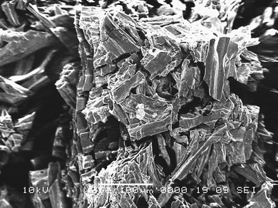 | ||
| Fig. 1 Scanning electron micrograph of part of pMDF strip. | ||
The melting temperature of the eutectic carbonate mixture is 525 °C, hence this is the lowest operational temperature of the cell to enable wetting of the pMDF. Three different preparatory treatments were investigated, (i) dipped in molten eutectic, (ii) impregnated with aqueous solution of eutectic mix, and (iii) powdered and mixed with carbonate powder. More intimate contact of the pMDF with the carbonate may promote the partial oxidation of C to CO when in the cell, and a comparison may be drawn with the well known alkali metal carbonate promoted gasification of coal to CO at high temperatures under CO2 or steam streams.23
In order to ascertain the HDCFC performance, current–voltage curves (Fig. 2) were measured over cell operating temperatures of 525–800 °C for the three pMDF samples. The y-axis intercept (I = 0) gives the OCV for the cell at each operating temperature Fig. 3 shows typical a.c. impedance data, for pMDF dipped in molten carbonate, depicting how the increase in temperature affects the cell resistance. An a.c. impedance allows two major parameters of the cell's resistance to be established, series resistance, Rs, which is the ohmic resistance and Rp, which is the total polarisation resistance for the cell due to the electrochemical reactions occurring at the various interfaces in the cell. Typically the Rs value is obtained from the high frequency intercept of the impedance arc(s) and the Rp value from the low frequency intercept of the electrode arc(s), e.g. see Fig. 3. At lower temperatures a significant diffusion element, i.e. inclined slope, can be seen sometimes and Rp values were not determined in such cases. The total resistance measured at open circuit potential by impedance can be compared to the resistance from the potential scan obtained from the slope of the I–V plot near OCV.
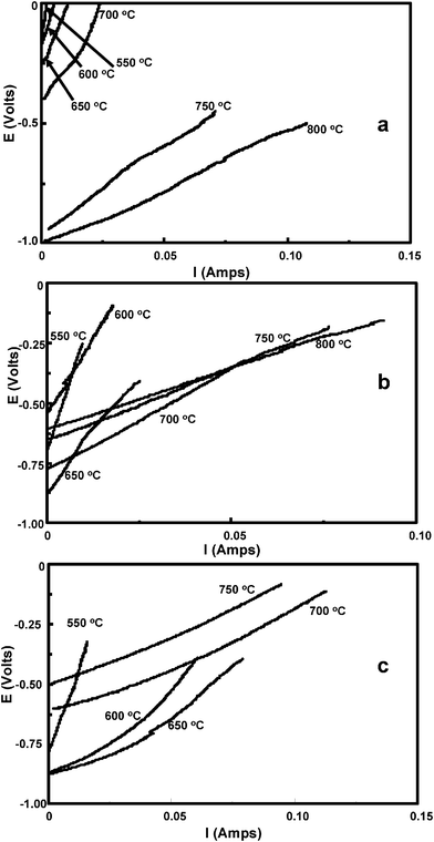 | ||
| Fig. 2 I–V plots at different temperatures for HDCFCs containing (a) pMDF dipped in molten eutectic; (b) pMDF soaked in saturated aqueous solution of alkali metal carbonate salts; (c) untreated powdered pMDF. | ||
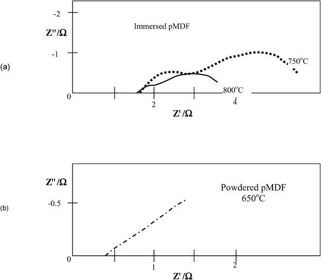 | ||
| Fig. 3 Complex impedance plots for (a) pMDF dipped in molten eutectic; (b) powdered pMDF. | ||
In the case of (i) pMDF dipped in molten carbonate, we see that the OCV is very low but rises to a good value of 1.0 V at 700 °C and 750 °C. The Rtotal values obtained with increasing temperature can also be seen to be decreasing, becoming the lowest values obtained at 800 °C. Sample (ii) pMDF soaked in aqueous alkali metal carbonate solution, shows higher OCVs at low temperatures, although OCV decreases at 700 °C. The calculated total cell resistance does decrease with temperature and at below 700 °C is lower than that for sample (i). For sample (iii) untreated powdered pMDF, at lower temperatures the OCV is larger in magnitude and the cell resistances are lower. However, at 700 °C and above, OCV falls and resistance increases. The fact that 10 s of mA can be drawn at 550 °C after pyrolising for 5 h at 500 °C strongly suggests that the pMDF rather than any off-gases are being oxidised, consistent with prior studies on other carbons.12–15 At higher temperatures secondary pyrolysis gases could be available for oxidation; however, as previously observed the reaction between carbon and CO2, through the Boudouard reaction will increase the yield CO for oxidation.15
A summary of the electrochemical data obtained is presented in Tables 1–3. The cell total resistances from the I–V curves are depicted in Fig. 4. From this it can be clearly seen that the powdered pMDF (i.e. no contact with carbonate prior to addition into the cell) has the lowest overall resistance at all temperatures observed, especially below 700 °C; however contact is lost at 800 °C. Above 700 °C, differences in resistance between the pMDF samples are small.
| Temperature/°C | OCV/V | Resistance (from I–V curve)/Ω (±5%) | R s (from impedance data)/Ω (±5%) | R p (from impedance data)/Ω (±5%) |
|---|---|---|---|---|
| a R s is the ohmic resistance due to the cell components; Rp is the total resistance for the cell due to all the components and the electrochemical reactions occurring. Errors estimated from limits of fit. | ||||
| 525 | −0.17 | 65 | 9.0 | 60.2 |
| 550 | −0.18 | 66 | 7.2 | 64.3 |
| 600 | −0.18 | 30 | 4.0 | 23.0 |
| 650 | −0.29 | 12.7 | 2.6 | 14.0 |
| 750 | −1.00 | 7.0 | 1.7 | 4.0 |
| 800 | −1.02 | 3.6 | 1.6 | 2.2 |
| Temperature/°C | OCV/V | Resistance (from I–V curve)/Ω (±5%) | R s (from impedance data)/Ω (±5%) | R p (from impedance data)/Ω (±5%) |
|---|---|---|---|---|
| 525 | −0.40 | 44.4 | 4.2 | — |
| 550 | −0.75 | 44.2 | 3.4 | — |
| 600 | −0.59 | 18.4 | 2.3 | 14.7 |
| 650 | −0.90 | 17.2 | 2.1 | 13.3 |
| 700 | −0.85 | 7.3 | 1.9 | 5.9 |
| 750 | −0.68 | 5.6 | 1.8 | 3.5 |
| 800 | −0.66 | 4.6 | 1.7 | 3.3 |
| Temperature/°C | OCV/V | Resistance (from I–V curve)/Ω (±5%) | R s (from impedance data)/Ω (±5%) | R p (from impedance data)/Ω (±5%) |
|---|---|---|---|---|
| 525 | −0.85 | 31.4 | 2.1 | — |
| 550 | −0.81 | 26.2 | 2.1 | |
| 600 | −0.89 | 3.3 | 1.3 | — |
| 650 | −0.89 | 2.3 | 0.88 | 6.4 |
| 700 | −0.62 | 3.1 | 0.91 | 3.8 |
| 750 | −0.58 | 3.3 | 1.23 | 2.6 |
| 800 | +0.04 | 4.9 | 1.33 | — |
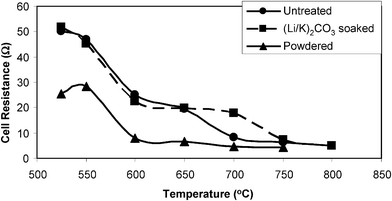 | ||
| Fig. 4 Comparison of total cell resistances (from initial slopes of I–V curves) at various temperatures. | ||
An a.c. impedance was measured at OCV; a typical plot for the immersed or soaked pMDFs is shown in Fig. 3(a). We see here three distinct elements in the impedance plots, the high frequency intercept is the ohmic resistance and the two semi-circles associated with the electrochemical reactions in the cell. The top of the semicircle with maximum Z″ has, in general, frequencies of ca. 1 kHz and ca. 5 Hz, possibly associated with the transfer of oxygen ions at the electrode : electrolyte interface and diffusion of reactant species through the electrode respectively, if we draw an analogy with the SOFC cathode reaction studies of Jorgensen et al.,24 although this will need further investigation to confirm. The behaviour is quite different for the powdered samples and although the ohmic resistances are much lower, the polarization behaviour shows much stronger diffusion limitations, see Fig. 3(b). The higher frequency polarization arc is not seen; however, an arc at ca. 20 Hz is apparent at higher temperature and this is generally associated with a Warburg type diffusion element such as that shown in Fig. 3(b).
| Sample | E a (from Rp)/eV (±0.03 eV) | E a (from Rs)/eV (±0.05 eV) |
|---|---|---|
| Dipped | 0.31 | 0.79 |
| (Li/K)2CO3 soaked | 0.58 | 1.00 |
| Powder (low temp.) | 0.48 | 0.82 |
| Powder (high temp.) | Not thermally activated | 0.82 |
The Rp and Rs values (Tables 1–4) enable calculation of relative activation energies for the electrochemical processes in each cell (Fig. 5). Fig. 5 shows two Arrhenius type plots based upon the inverse polarization and ohmic resistances. The lines in Fig. 5(a) are calculated from the ohmic contribution of the cell, and those in Fig. 5(b) from the polarisation resistance. In Fig. 5(a) there are changes in the apparent activation energies due to the level of reactivity and contact of the fuel with the electrode and current collection ability of the cell. In the case of the dipped cell we see a relatively low activation energy of 0.31 eV which is less than for the dipped system (0.58 eV). For the powdered sample, there is a distinct change in the gradient at ca. 1.1 on the x-axis (i.e. T = 650 °C) from 0.48 eV. Below 650 °C it is likely that there is sufficient active fuel to allow greater reactivity and as the experiment proceeds to higher temperatures, the fuel depletes or its surface becomes less available and the reaction slows down. Ohmic contact within the cell may also be lost as the temperature is increased. In Fig. 5(b) all three lines have similar gradients: the dipped system (1.00 eV), the soaked system (0.79 eV), the powdered system (0.82 eV). Such values are comparable to literature values for the ionic conductivity of 8 mol%, which is about 1 eV,25 suggesting that the electrochemical process may be limited by ionic mobility through the zirconia electrolyte. The activation energy calculated from the ohmic resistance compared with the YSZ activation energy is lower and may indicate that transport is limited ionically by the melt or electronically in the current collection.
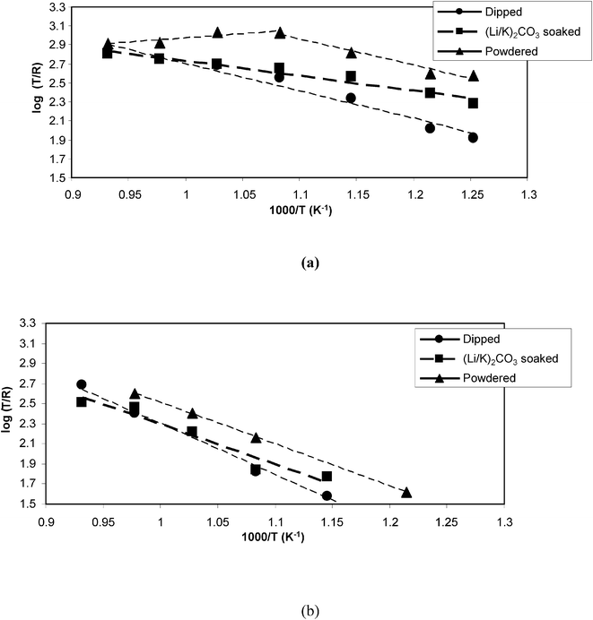 | ||
| Fig. 5 Activation energy plots for cell reactions, derived from a.c. impedance data (a) Rs (b) Rp | ||
Conclusions
In these experiments pMDF has proven to be a very good fuel for the HDCFC system yielding powers as high as 50 mW from cells of a few cm2 geometric area, moreover cell activity is dependent upon the preparatory treatment of the pMDF sample. Powdered pMDF, due to its greater surface area relative to unpowdered samples, gives lower cell resistances below 700 °C, but HDCFCs powered by pMDF sticks which had received carbonate treatment attain approximately similar resistance values above 700 °C. The OCV values are clearly higher at lower temperature range for the powdered pMDF. The resistance values and OCVs we have obtained with pMDF, particularly at higher cell temperatures, are among the best to date with the HDCFC concept. The ability of the HDCFC to perform well with incompletely pure carbon is in keeping with earlier results12–14 and demonstrates that the cell design is versatile enough to use a range of carbonaceous materials.Upon eventual scale-up of the tubular HDCFC design, solid carbon feedstock would be preferable to powdered feedstock, for ease of loading. It is clear from the results presented that strips of pMDF require contact with carbonate mixture to give good cell performance, and even then performance below 700 °C is inferior to powdered pMDF. Due to ease of handling, carbon processing with aqueous carbonate is more attractive than using molten carbonate for this purpose.
Acknowledgements
The authors would like to thank Scottish Enterprise, Dstl and EPSRC for funding.References
- J. T. S. Irvine, S. W. Tao, S. L. Jain, J. C. Bradley, J. B. Lakeman and K. D. Pointon, Proc. World Renewable Energy Conference (WREC 2005), Ed. M. Imbabi and C. P. Mitchell, Elsevier, New York Search PubMed.
- D. Cao, Y. Sun and G. Wang, J. Power Sources, 2007, 167, 250–257 CrossRef CAS
.
- W. W. Jacques, Harper's Mag., 1896, 94, 144–150 Search PubMed
.
- S. Zecevic, E. M. Patton and P. Parhami, Carbon, 2004, 42, 1983–1993 CrossRef CAS
.
-
M. Anbar, D. F. McMillen, R. D. Weaver and P. J. Jorgensen. US Pat. 3970474, 1976
.
-
J. F. Cooper, R. L. Krueger and N. J. Cherepy. US Pat. 0017380 A1, 2003
.
-
P. V. Pesavento, US Pat. 6200697 B1, 2001
.
-
T. T. Tao, W. Bai, A. P. Blake, J. K. Kura and G. Wang, WO Pat. 03067683, 2003
.
-
J. F. Cooper, US Pat. 2006019133, 2006
.
- T. Nunoura, K. Dowaki, C. Fushimi, S. Allen, E. Mészáros and M. J. Antal, Ind. Eng. Chem. Res., 2007, 46, 734–744 CrossRef CAS
.
- A. C. Lee, S. Li, R. E. Mitchell and T. M. Gur, Electrochem. Solid-State Lett., 2008, 11, B20–B23 CrossRef CAS
.
- S. L. Jain, J. B. Lakeman, K. D. Pointon and J. T. S. Irvine, J. Fuel Cell Sci. Technol., 2007, 4, 280–282 CrossRef CAS
.
- K. D. Pointon, J. B. Lakeman, J. T. S. Irvine, J. C. Bradley and S. L. Jain, J. Power Sources, 2006, 162, 750–756 CrossRef CAS
.
- S. L. Jain, J. B. Lakeman, K. D. Pointon and J. T. S. Irvine, Electrochem. Soc. Trans., Proc. Int. Symp. SOFC X., 2007, 7, 829 Search PubMed
.
- Y. Nabae, K. D. Pointon and J. T. S. Irvine, Energy Environ. Sci., 2008, 1, 148 RSC
.
- Wood Panel Industries Federation website http://www.wpif.org.uk/publications/PressRelease-MDF.pdf.
- A. K. Kercher and D. C. Nagle, Carbon, 2002, 40, 1321–1330 CrossRef CAS
.
- T. Nakai, S. K. Kartal, T. Hata and Y. Imamura, Buildings Environ., 2007, 42, 1236–1241 Search PubMed
.
- Q. Gan, S. J. Allen and R. Matthews, Waste Manage., 2004, 24, 841–848 CrossRef CAS
.
- J. Li and S. J. Li, J. Wood Sci., 2006, 52, 331–336 CrossRef CAS
.
- Zplot and Correware software, Scribner Associates Inc., North Carolina, US.
- S. L. Jain, V. L. Budarin, D. J. Macquarrie, B. Lakeman, K. D. Pointon and J. T. S. Irvine, Carbon, 2006 Search PubMed
Conf. Proc., ISBN 0-9553365-1-1.
- A. C. Sheth, C. Sastry, Y. D. Yeboah, Y. Xu and P. Agarwal, Fuel, 2004, 83, 557–572 CrossRef CAS
.
- M. J. Jørgensen and M. Mogensen, J. Electrochem. Soc., 2001, 148, A433–A442 CrossRef CAS
.
- I. R. Gibson and J. T. S. Irvine, J. Mater. Chem., 1996, 6, 895–898 RSC
.
| This journal is © The Royal Society of Chemistry 2009 |
