Photodriven heterogeneous charge transfer with transition-metal compounds anchored to TiO2 semiconductor surfaces†
Shane
Ardo
and
Gerald J.
Meyer
*
Johns Hopkins University, 3400 North Charles Street, Baltimore, MD 21218, USA
First published on 1st December 2008
Abstract
A critical review of light-driven interfacial charge-transfer reactions of transition-metal compounds anchored to mesoporous, nanocrystalline TiO2 (anatase) thin films is described. The review highlights molecular insights into metal-to-ligand charge transfer (MLCT) excited states, mechanisms of interfacial charge separation, inter- and intra-molecular electron transfer, and interfacial charge-recombination processes that have been garnered through various spectroscopic and electrochemical techniques. The relevance of these processes to optimization of solar-energy-conversion efficiencies is discussed (483 references).
 Shane Ardo | Shane Ardo was born in San Francisco, California in 1977. He obtained a BS in mathematics from Towson University in 1999 and an MS in nutrition and food science from UM-College Park in 2005. Since joining Johns Hopkins University for a PhD program in chemistry, Shane has been awarded an MS degree and was recently selected to describe renewable energy sources at the inaugural Eaton E. Lattman lecture series. He currently studies molecular, photo-induced processes at nanocrystalline TiO2 interfaces for application in dye-sensitized solar cells and photoelectrosynthetic hydrogen formation. Shane also enjoys soccer, hiking, and camping with his fiancée and friends. |
 Jerry Meyer | Gerald (Jerry) J. Meyer was born in Oconomowoc Wisconsin in 1962. He received a BS in chemistry and mathematics from SUNY-Albany and a PhD in chemistry from UW-Madison. After a post-doctoral appointment at UNC-Chapel Hill, he joined the faculty at Johns Hopkins University in 1991 where he is now the Bernard N. Baker Professor of Chemistry with a joint appointment in the Materials Science & Engineering Department. In addition to his interests in environmental chemistry and solar energy conversion, Jerry enjoys long distance running, tennis, cooking, gardening, hiking, and spending time with his wife, Lisa, and daughters, Caroline and Jillian. |
1. Introduction
A Rationale
Hoffert has elegantly documented recent power needs on the terawatt (TW = 1012W) scale.1,2 As the worldwide rate of energy expenditure is directly related to the number of people on Earth, the population growth experienced over the last quarter-century is staggering: a 45% increase which equates to roughly two billion people and 6 TW of additional power (∼63% increase).3 This coupled with the urbanisation of third-world and industrialized nations and cities has led to an increase in the demand for fuel that has subsequently driven gas and oil prices to record highs.3 Regardless of their price, the continued use of fossil fuels cannot be a long-term solution as they come from a limited stock and the deleterious environmental consequences of their combustion have become self-evident. Thus, the numbers alone, i.e. population, energy demand, and fuel prices, do not convey the severity of the problem. Concern should be elicited as the ice-core data over the past three-quarters-of-a-million years correlates temperature with greenhouse gas concentration5,6 and current atmospheric CO2 levels of >380 ppm4 exceed any values attained over this same time period.5 Further, outside of natural photosynthesis, there exist no means by which our society could significantly lower the concentration of CO2. The increased average global temperature and rates of glacial melting measured over the last few decades are telling signs.7 There is real reason for concern. Regardless of one’s opinion on the causes of global climate change, it is very difficult to argue with two key points: (1) humans need to conserve energy and (2) commercially viable and sustainable energy conversion processes need to be discovered, designed, and developed.The motivation for this review stems from the urgent need for inexpensive and sustainable materials that can be used for solar energy conversion. Hoffert and co-workers concluded that in order to avoid catastrophic planetary changes Earth will require at least 10 terawatts of carbon-neutral energy by the year 2050, which was approximately equal to the worldwide energy requirement in the year 1998.1,2 They also described the pitfalls of a ‘wait-and-see’ approach and recommended immediate action. It has now been dubbed the Terawatt Challenge.8 The sun is the one source that on its own could supply the world’s projected energy demand and in a sustainable fashion.4 To put it in perspective, the amount of solar energy reaching the earth in one day could power the planet for an entire year.8,9 Remaining is the challenge of harvesting and storing this energy in a cost-effective way. It is our assumption that molecular approaches to this challenge will ultimately be most successful. The relative ease by which the spectroscopic and electrochemical properties of molecules can be tuned through synthetic manipulation allows for many minute variations on solar-energy-conversion schemes to be rapidly studied. Additionally, chemical bonds afford large energy storage capacities, i.e. energy densities, and power densities that exceed those obtainable from most other storage methods.
B Background
When we started our research program at Johns Hopkins University in 1991, molecular approaches to solar-energy conversion were solely of academic interest. The hard fact was that the most efficient “molecular solar cells” were comprised of cold water running over illuminated black paint. In the same year much progress in the field was realized when Grätzel and O’Regan reported an order-of-magnitude increase in solar light-to-electrical power conversion efficiency from dye-sensitized solar cells (DSSCs).10 Their significant advance was to replace the planar electrode materials of the past with high surface area, mesoporous, nanocrystalline semiconductor thin films. The actual surface area for sensitizer‡ binding was up to three orders-of-magnitude larger than the geometric surface area, which is critical for solar harvesting with molecular compounds.11 Today, confirmed efficiencies in excess of 10% have been established.12The general mechanisms for light-to-electrical power conversion in DSSCs were developed in early sensitization studies of planar and single-crystal semiconductors. Mechanisms like that shown in Fig. 1 can be found in many excellent reviews on this area.11,13 In short: (I) light is absorbed by a sensitizer to form a molecular excited state; (II) the excited state may inject an electron into the semiconductor thus causing charge separation; (III) the oxidized sensitizer is “regenerated” by an external electron donor. Once the electron has performed useful work in the external circuit, it returns to a counter electrode where it reduces the oxidized electron donor. Hence the solar cell is termed ‘regenerative’ as all oxidation chemistry at the dye-sensitized electrode is reversed at a dark counter electrode such that no net chemistry occurs. It is now possible to include rate constants and/or current densities for many of these processes as well as for (IV) the unwanted charge recombination of TiO2 electrons to: (A) oxidized sensitizers; or (B) oxidized donors in the electrolyte. There are a tremendous number of details in an operational Grätzel-type cell and the values in Fig. 1 represent a good starting point for their general comparison. However, the time scales and current densities are often misleading as they may be specific to a certain class of sensitizers or electrolytes and/or may be abstracted from experimental data obtained in the absence of some components of the operational Grätzel-type cell.§
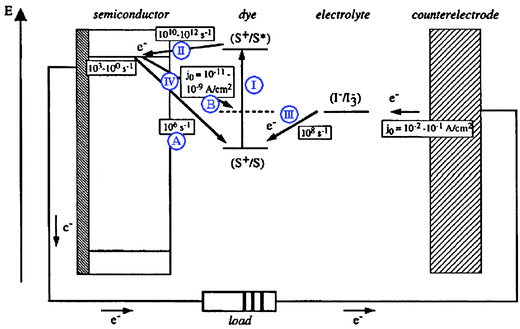 | ||
| Fig. 1 A schematic depicting a champion dye-sensitized solar cell (DSSC) illustrating the approximate relative energetics of individual electron-transfer reactions along with their corresponding rate constants or current densities. The steps highlighted in this review are shown as blue Roman numerals and subcategorized by capitalized letters: (I) sensitizer light absorption; (II) excited-state electron injection; (III) regeneration of the oxidized sensitizer by an electron donor in the electrolyte; (IV) charge recombination of TiO2 electrons, TiO2(e−)s, to (A) oxidized sensitizers or (B) oxidized donors. Adapted from Fig. 9 of ref. 11. | ||
In this review we provide some of the details that have arisen from recent research of heterogeneous, charge-transfer processes involved in the transduction of energy in TiO2-based DSSCs. They predominantly deal with actions occurring at mesoporous, nanocrystalline TiO2 (anatase) electrodes sensitized to visible light with transition-metal coordination compounds. Space limitations prevented us from including results obtained in the active areas of research with organic and quantum dot sensitizers. The review highlights molecular insights into the interfacial, charge-transfer processes I–IV that have been garnered through various spectroscopic and electrochemical measurements. As this review illustrates, many of the details remain poorly understood. Notwithstanding, numerous interesting and informative studies have been performed in order to probe electrolyte- or counter electrode-based phenomena15 as well as charge transport through mesoporous films.16–20 These will be discussed only as they are relevant to processes I–IV.
Understanding the operation of a Grätzel cell is not the only reason to study excited states and interfacial electron transfer at semiconductor interfaces on the molecular level, a point often missed by reviewers in this area. Indeed the spirit of using inexpensive processing and non-toxic, abundant, high surface-area materials for solar-energy conversion is exactly on track.13 It is a sound approach toward practical solutions to the Terawatt Challenge that could ultimately provide future generations the relatively low-cost power that we enjoy today, but in a sustainable fashion.8 To build on the success of the Grätzel cell and develop low-cost materials capable of solar-energy conversion and storage is just one of many motivations for understanding interfacial charge transfer in precise molecular detail.
2. Solar harvesting with metal-polypyridyl compounds
One sun of solar irradiance at an Air Mass of 1.5 (AM1.5) and under standard, U.S. atmospheric conditions (1000 W m−2) is often taken as an average irradiance and spectral distribution of sunlight in the United States. The spectrum is available in downloadable format form the National Renewable Energy Laboratory (NREL) website.21 The fraction of light that is absorbed by a DSSC is wavelength dependent and is often called the light harvesting efficiency (LHE) or the more generally preferred IUPAC name, absorptance (α(λ)).22 The absorptance of a monolayer of sensitizers anchored to a flat surface is related to (a) the molar extinction coefficient of the sensitizer, ε(λ), and (b) the surface area occupied by the dye, ADye, i.e. the footprint: | (1) |
 | (2) |
The effectiveness of a solar cell is measured by its power output. This value is the product of its current and voltage. Thus, determination of the solar cell’s current–voltage relationship often aids in assessing its performance, Fig. 2. The light-to-electrical power conversion efficiency of a solar cell (η) is the product of the open-circuit photovoltage (Voc), short-circuit photocurrent (isc), and fill factor (FF) divided by the product of the incident irradiance (Po) and the area of the solar cell (Acell).24
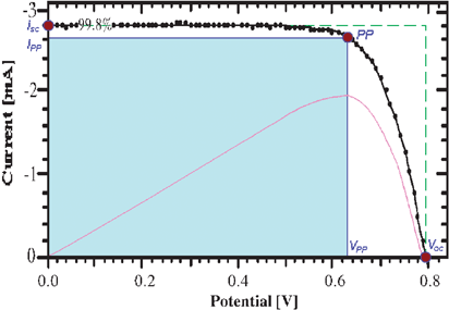 | ||
| Fig. 2 Typical current–voltage curve for a champion DSSC under approximately 1 sun, AM1.5 illumination (0.998 suns). Labeled are the short-circuit photocurrent (isc), open-circuit photovoltage (Voc), and power point (PP) along with its corresponding photovoltage (VPP) and photocurrent (iPP). The fill factor (FF) is the area of the shaded region, which is bounded by the VPP and iPP, divided by the area of the region outlined by the dashed line, which is bounded by the Voc and isc. The curve in magenta represents the power as a function of voltage in arbitrary units further illustrating that the PP coincides with the condition of maximum power output. Adapted from Fig. 6 of ref. 26. | ||

| (3) |
A subtlety is that the isc of a solar cell is directly related to its absorptance (α), but not its absorbance. The absorbances and absorptances are approximately equal at low sensitizer concentrations but differ significantly at the high sensitizer concentrations used in champion DSSCs. Therefore, the normalized photocurrent action spectrum, i.e. a plot of the incident photon-to-current efficiency (IPCE), or external quantum efficiency, as a function of excitation wavelength, should coincide with the normalized sensitizer absorptance spectrum. One is often interested in not only the monochromatic absorptance but the integrated, α(λ)-weighted solar flux divided by the total 1 sun, AM1.5 photon flux as well. The latter represents the overall percentage of solar light absorbed where the numerator serves as an upper limit to the isc of the DSSC.
The FF can be related to isc and Voc through the corresponding values at the power point (PP):
 | (4) |
A Orbitals and electronic transitions
The metal-to-ligand charge transfer (MLCT) excited states of dπ6 coordination compounds have emerged as the most efficient for solar harvesting and sensitization of wide-bandgap semiconductor materials. As the name implies, light absorption promotes an electron from the Metal d orbitals to the Ligand π* orbitals, d(π) →π*.27–29 A number of electric-dipole-allowed Charge-Transfer transitions are observed which give rise to intense absorption bands in the visible region with moderate extinction coefficients. There is no formal spin for each excited state due to heavy-atom spin–orbit coupling from the transition-metal center (especially for 4d and 5d metals).30,31 Crosby et al. have proposed that the excited state is accurately described by solely the symmetry label of the molecular point group to which it belongs, corresponding to an irreducible representation, and not the spin and an orbital individually.30 The effects of spin–orbit coupling must be introduced in order to rationalize the relative oscillator strengths and absorption spectra of M(bpy)32+ (M = FeII, RuII and OsII) compounds, where bpy is 2,2′-bipyridine.The classical example of a compound with such transitions is Ru(bpy)32+ which is arguably the most well-studied, coordination compound. Its lowest-energy state is three-fold symmetric and is best described by the symmetry label D3, Fig. 3. Based on the Franck–Condon principle, immediately following excitation the initial excited state ought to possess the same structural symmetry as the ground state.32–34 Thus, in the absence of Jahn–Teller distortions or solvent-induced fluctuations, the initial, Franck–Condon excited state formed via an MLCT transition in Ru(bpy)32+ could consist of a delocalized electronic wavefunction on all three bpy ligands each formally possessing 1/3 of an electronic charge. Monitoring the conversion of this excited-state from D3 to C2 symmetry is a non-trivial task, although some evidence supports the notion that conversion occurs by T2 dephasing.35,36 Based on the absence of an electric dipole for D3 symmetry molecules and minor, but clearly observable, solvent-dependent, ground-state MLCT absorption features, the initial excited-state electron is thought to localize on a single bpy.37 Time-resolved resonance Raman spectroscopy of Ru(bpy)32+ shows clear evidence for localization on nanosecond and longer time scales.38 This localized excited state has the reduced-symmetry designation C2 and an estimated dipole moment of ∼10 Debye.37,39
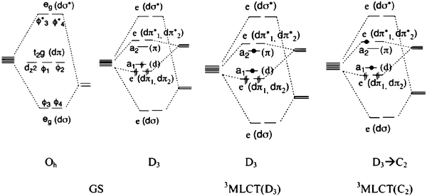 | ||
| Fig. 3 Molecular-orbital diagrams for Ru(L)62+-type compounds in their ground state with: GS-Oh) octahedral, Oh, symmetry; or GS-D3) reduced D3 symmetry, like for Ru(bpy)32+. Also shown are excited-state molecular-orbital diagrams for: 3MLCT-D3) the initial, Franck–Condon excited state formed under the ground-state D3 symmetry, where the excited electron is delocalized equally over each ligand; and 3MLCT-C2) the excited state possessing reduced C2 symmetry where the excited electron is localized on one ligand. Taken from Fig. 2 of ref. 40. | ||
Demas and colleagues have shown that intersystem crossing to a manifold of relaxed, MLCT excited states occurs with a quantum yield near unity in fluid solution, Fig. 4(a).41–43 Although not formally triplet or singlet in nature, the predominantly triplet character of the lowest-energy excited state, 1 E′,44,45 and singlet character of the initial Franck–Condon state rationalizes why the transition between them is often termed intersystem crossing. It is for this reason that these states will be labeled as 3MLCT and 1MLCT, respectively, throughout this review. Crosby, Hager, and colleagues have shown that photoluminescence (PL) arises from three closely spaced electronic states.46–50 Rapid thermal equilibrium between this manifold of states, <kT in energy apart, happens such that PL occurs from what appears to be a single thermally equilibrated excited state, or thexi state.51,52 Yersin et al. discovered evidence for two more highest-energy states by temperature-dependent emission polarization experiments and labeled them per the D3′ double symmetry group, which takes into account the spin–orbit coupling, Fig. 4(b).44,45 These transitions are generally supported by those obtained from computational Density Functional Theory (DFT) calculations.53
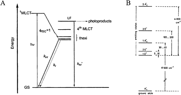 | ||
| Fig. 4 (A) A Jablonski-type energy diagram for Ru(bpy)32+ illustrating its manifold of thermally equilibrated excited states, i.e. the thexi state. The quantum yield for intersystem crossing, ϕISC, is approximately unity. Taken from Scheme 1 of ref. 54. (B) The relative energy levels for the excited states of Ru(bpy)32+ under the D3′ double group, which takes spin–orbit coupling into consideration. Taken from Fig. 3 of ref. 44. | ||
As many of the sensitizers employed in champion DSSCs are of the form cis-Ru(LL)2X2, where LL is a bpy-like ligand and X is a non-chromophoric ligand, their spectral differences and similarities to Ru(bpy)32+ are discussed. When LL = bpy and X = NC− the compound’s spectrum is solvatochromic and the RuIII/IIreduction potential, Eo(RuIII/II), is more negative as compared to Ru(bpy)32+.55 This coupled with the relatively insensitive energetics of the π* orbitals of the bpy ligand leads to red-shifted absorption and emission maxima. These lowest-energy, actinic transitions are MLCT in nature and result in an electron on the bpy-based chromophoric ligand and a hole that is partially delocalized on the cyano ligands, thus greatly decreasing the Lewis basicity of the cyano ligands. The most efficient sensitizer for DSSCs is called N3, where LL = 4,4′-dicarboxylic acid-bpy (dcb) and X = SCN−.25 Although less solvatochromic than the cyano derivative, its visible absorption spectrum, and that of its ‘LL = bpy’ derivative, exhibit two well-resolved bands. It has been postulated that this occurs due to a shift in the electron density of the highest occupied molecular orbital (HOMO) from the RuII-metal center to the isothiocyanate ligands.56–58 By DFT it was calculated that ∼75% of the HOMO density resides on the isothiocyanate ligands and that ∼75% of this density resides on the sulfur atom.
B Tuning of the absorption spectrum and redox properties
An important aspect of dπ6 coordination compounds is that their colors can be widely tuned using synthetic chemistry. The MLCT absorption bands can be tuned in energy by altering the substituents on the bpy ligands or by controlling the extent of d(π)-π* back-bonding donation to nonchromophoric ligands. How these changes affect the photophysical properties of the compounds have been the subject of many investigations affording further insights into the factors that govern radiative and nonradiative excited-state decay. As just mentioned, the compound that has emerged as the most efficient sensitizer for DSSC application is N3.25 N3 gains red absorption over Ru(dcb)32+ however at the expense of the Eo(RuIII/II). Although not generally vital to DSSCs, this loss in driving force for regeneration of the oxidized sensitizer would further limit the sensitizer’s ability to perform a ‘holy grail’ of chemistry: water oxidation.59,60 However, in terms of DSSC light-to-electrical power conversion efficiency, N3 and closely related analogues remain unsurpassed, Fig. 5.¶ A similarly successful RuII-based sensitizer, which is based on terpyridine rather than bpy, is the so called ‘black dye’: [Ru(tct)(NCS)3]−, where tct is 4′,4″,4‴-tricarboxylic acid-tpy and tpy is 2,2′:6′,2″-terpyridine. It extends the spectral sensitivity of the solar cell significantly towards the red as compared to N3.68 However, a lower extinction coefficient throughout the visible region results in an overall less-efficient DSSC.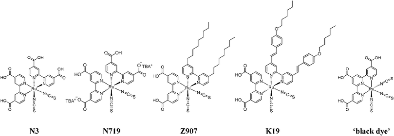 | ||
| Fig. 5 The chemical structures of the most successful RuII-based sensitizers employed in champion DSSCs. | ||
The reduction potentials of the thexi state of the sensitizers, Eo(RuIII/II*) and Eo(RuII*/+), can be estimated using thermochemical cycles.69,70 In many cases the spectroscopic and electrochemical data needed for such calculations can be measured in situ, i.e. for the sensitizer anchored to the semiconductor film. Previous studies have shown that molecules anchored to mesoporous, nanocrystalline TiO2, ZrO2, or Al2O3 thin films can be reversibly oxidized in standard electrochemical cells provided that the surface coverage exceeds a percolation threshold.71–73Cyclic voltammetry and spectroelectrochemistry are thus powerful in situ tools for determining formal reduction potentials and absorption spectra of relevant redox states. The excited-state reduction potential for the oxidation of the thermally equilibrated excited state, Eo(RuIII/II*), is calculated by the following equation:
| Eo(RuIII/II*) = Eo(RuIII/II) −ΔGES | (5) |
As previously mentioned, Ru(bpy)32+ and most other tris-heteroleptic RuII compounds have redox and optical properties that are fairly insensitive to their environments.37,76 However, this is not the case for ammine and cyano compounds of the type [M(bpy′)(X)4]2−,2+ or [cis-M(bpy′)2(X)2]0,2+, M = Fe, Ru, or Os and X = CN− or NH3.76 Outer-sphere interactions with the cyano ligands have a profound influence on Eo(MIII/II) and hence the color of the compound. [Ru(dcb)(CN)4]2− is highly solvatochromic;78 the maximum of the lower-energy MLCT band of Ru(dcb)(CN)4/TiO2 was observed at 450 ± 10 nm in tetrahydrofuran and at 500 ± 20 nm in dimethylformamide.78 The color change was due to a shift of Eo(RuIII/II) with solvent. The complex maintained this solvatochromism upon attachment to mesoporous, nanocrystalline TiO2 (anatase) thin films although the magnitude of the effect decreased. Solvent tuning altered the spectral responses of DSSCs based on these materials in a predictable way. For [Fe(bpy)(CN)4]2− compounds, the excited-state reorganization energy in acetonitrile was found to be significantly larger on TiO2 than in fluid solution (λ = 0.32 eV versus 0.10 eV, respectively).77 This increased reorganization energy may be due to the restricted translational mobility of the semiconductor-bound iron compounds and the ambidentate FeII–CN–TiIV linkages. Interestingly, a recent Raman study has shown that when anchored to TiO2, the solvent reorganization energy of N3 decreased by a factor of six.79 Further studies are needed to provide fundamental information on the solvation environment of similar semiconductor-bound molecules.
A shortcoming of actinic sensitization by MLCT transitions is their relatively low extinction coefficients as compared to π→π* transitions often found in organic sensitizers. Thus 6–10 μm thick films of nanocrystalline TiO2 are required for efficient solar harvesting and increased LHE with RuII-based coordination compounds. This precludes the use of many classes of semiconductor materials that have inherently low surface areas. Ru(bpy)32+ has a molar extinction coefficient of about 15![[thin space (1/6-em)]](https://www.rsc.org/images/entities/char_2009.gif) 000 M−1 cm−1 for its MLCT-based electronic transitions.80 In contrast, natural and synthetic organic pigments also absorb solar photons but with extinction coefficients that are often in excess of 200000 M−1 cm−1.23 It has long been known that addition of substituents to bpy with low lying π orbitals (such as aromatics, esters, carboxylic acids, or unsaturated organics) can enhance MLCT extinction coefficients relative to unsubstituted bpy.65–67,81–85 Interestingly, 4 and 4′ disubstitution of bpy has been found to increase these extinction coefficients more effectively than does disubstitution in the 5 and 5′ positions.86 The preparation of high extinction coefficient, heteroleptic N3 derivatives, where one of the dcb ligands is replaced by a 4,4′-disubstituted bpy is an extremely active area of research.65–67,82,84,85,87
000 M−1 cm−1 for its MLCT-based electronic transitions.80 In contrast, natural and synthetic organic pigments also absorb solar photons but with extinction coefficients that are often in excess of 200000 M−1 cm−1.23 It has long been known that addition of substituents to bpy with low lying π orbitals (such as aromatics, esters, carboxylic acids, or unsaturated organics) can enhance MLCT extinction coefficients relative to unsubstituted bpy.65–67,81–85 Interestingly, 4 and 4′ disubstitution of bpy has been found to increase these extinction coefficients more effectively than does disubstitution in the 5 and 5′ positions.86 The preparation of high extinction coefficient, heteroleptic N3 derivatives, where one of the dcb ligands is replaced by a 4,4′-disubstituted bpy is an extremely active area of research.65–67,82,84,85,87
We recently found that employing bpy ligands bridged in the 3 and 3′ positions by dithiolene is a viable alternative to the more traditional and widely pursued approach of introducing conjugated groups in the 4 and 4′ positions.81 Substituent effects in this position are not as well documented as they sterically force the two pyridyl rings out of planarity, behavior that can decrease the stability of the compound. This issue is circumvented with bridging ligands but at the expense of opening up the N–Ru–N bite angle thereby stabilizing ligand-field states and decreasing the excited-state lifetime. Nevertheless, it was notable that these first-derivative, MLCT-dithiolene compounds have extinction coefficients for their lowest-energy transitions that are comparable to the highest ever reported based on RuII(4,4′-disubstituted-bpy) compounds, 4.4 × 10⁴ M−1 cm−1. In a similar absorption region the largest value for the dyes often employed in champion DSSCs, Fig. 5, is 1.8 × 10⁴ M−1 cm−1 for K1966 and to the best of our knowledge no compounds exceed 3.9 × 10⁴ M−1 cm−1 beyond 450 nm.83,85 Part of this success was that the dithiolene-bpy ligands themselves have intraligand absorption bands, in addition to the MLCT absorption bands, in the visible region.
An alternative strategy for increasing the LHE is to use nature’s antenna effect, Fig. 6.88–94 Multiple pigments that are suitably arranged can absorb light and vectorally transfer their energy to a central pigment that can then inject an electron into the semiconductor. If the additional pigments do not increase the footprint of the sensitizer on the semiconductor surface, this is a method for enhancing the LHE. Indeed, the trinuclear RuII sensitizer utilized in the celebrated 1991 Nature paper had been previously designed in Italy to function as an antennae.91 An issue with the Ru(dcb)2(CN)2 group used as the energy transfer acceptor and surface anchor was the cis geometry of the ambidentate cyano ligands, which resulted in a larger footprint as the number of RuII pigments was increased. In this regard, a trans geometry is more preferred.95 The synthesis of molecules that function as antennae and their use in DSSCs continues to be an active area of research that may one day enable the efficient sensitization of planar semiconductor materials.93
![A scheme depicting an array of sensitizers bound to a planar TiO2 surface consisting of cis- and trans-[(Ru(bpy)2(pz))4(ina)]8+ on the left and right, respectively, where pz is ambidentate pyrazine and ina is isonicotinic acid. The trans orientation may allow for increased absorptance, α, without increasing the projected footprint of the sensitizer. Taken from Fig. 1 of ref. 95.](/image/article/2009/CS/b804321n/b804321n-f6.gif) | ||
| Fig. 6 A scheme depicting an array of sensitizers bound to a planar TiO2 surface consisting of cis- and trans-[(Ru(bpy)2(pz))4(ina)]8+ on the left and right, respectively, where pz is ambidentate pyrazine and ina is isonicotinic acid. The trans orientation may allow for increased absorptance, α, without increasing the projected footprint of the sensitizer. Taken from Fig. 1 of ref. 95. | ||
C Excited-state time scales
The excited-state lifetime of [RuIII(bpy)2(bpy−)]2+* is ∼1 microsecond in water.96 The radiative rate constant is typically about two orders-of-magnitude smaller than the non-radiative rate constant and hence the excited-state lifetime is controlled by the latter.96RuII- and OsII-polypyridyl excited states have been shown to follow Jortner’s Energy Gap Law, where the non-radiative rate constant increases exponentially with decreasing energy gap.97–101 For this reason, it has proven to be difficult to prepare compounds that emit in the infrared region and have long-lived excited states. A large ligand-field splitting parameter is required for the observation of long lifetimes in this class of excited states. The presence of low-lying, ligand-field states can rapidly deactivate MLCT excited states and decrease excited-state lifetimes. A classical example of this is Fe(bpy)32+ which, until recently, was thought to be completely non-emissive due to rapid and quantitative internal conversion/intersystem crossing through ligand-field states.As described further below, one fascinating aspect of DSSCs is the ultrafast excited-state injection into the semiconductor which has been observed under many experimental conditions.102–119 It is therefore useful to describe the time scales on which RuII-based coordination compounds undergo equilibration to their MLCT thexi states. Using transient absorption anisotropy measurements on Ru(bpy)32+ in acetonitrile, McCusker and colleagues have identified charge-localizing decoherence of the initial, Franck–Condon, D3-symmetrical excited state occurring with a lifetime of 59 fs.36 The kinetics were proposed to be coupled to inertial solvent dynamics as the lifetimes were solvent dependent in nitrile solvents and ranged from 59 to 173 fs in an order expected based on such a hypothesis. The contradictory conclusion that formation of such a C2-symmetrical excited state occurs immediately upon light excitation can be disregarded assuming a decoherent mechanism for the randomization of the initially formed, D3-symmetrical excited state.39,120 The reason for this was that the techniques previously employed, i.e. resonance Raman and Stark effect spectroscopy, solely report on coherent states, like that of the localized 1MLCT excited state, and not on delocalized states, like the initial, Franck–Condon excited state. Speculation of longer-lived charge hopping as a means of randomizing the ligand radical excited state is also not possible based on these observations, although the anisotropic results are still not fully understood.35,121,122
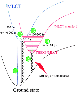
Subsequently, by femtosecond fluorescence upconversion it was shown that the lifetime of the 1MLCT excited state of Ru(bpy)32+ was 45 ± 15 fs. As this measurement directly probes the spin of the electrons, this lifetime is that of the true singlet-to-triplet intersystem crossing to the vibrationally ‘hot’ triplet manifold of states, Fig. 7–3.123 This value agrees well with those obtained in water using time-resolved, femtosecond stimulated Raman spectroscopy and polychromatic, femtosecond fluorescence upconversion.124,125 Spectral features lasting ∼300 fs and observed by femtosecond, magic-angle transient absorption spectroscopy were also assigned to relaxation of the charge-localized, 1MLCT excited state of Ru(bpy)32+ to the triplet-character thexi state.126 As this method probes the absorption of states and not spin directly, the reported half-time (t1/2 = ∼100 fs) provided an upper limit to the true intersystem-crossing lifetime. Additionally, it could be reporting on both intersystem crossing and vibrational cooling within the manifold of triplet-character states, Fig. 7–3 and 7–4, respectively. Further evidence for such a process was obtained by employing similar measurements, however in addition to the sub-picosecond component, a higher energy (360 nm), longer-lifetime (∼5 ps) transient feature was also present.35 As the ligand radical has a rather high extinction coefficient here, this component was assigned to vibrational relaxation to form the thexi state. This vibrational–relaxation lifetime within the manifold of states was shown to vary from ∼0.6 to 5.0 ps and be rather solvent dependent.35,123,127,128 Using picosecond Kerr-gated, time-resolved resonance Raman spectroscopy the lifetime of this relaxation was shown to be ∼20 ps for homoleptic and heteroleptic Ru(bpy)32+-based molecules of varying charges and isotopic compositions and in a variety of solvents.129 For comparison, N3′s 1MLCT excited-state t1/2 was reported to be ∼30 fs and thermal relaxation within its triplet-character manifold was found to occur with a ∼80 fs half-time when bound to mesoporous, nanocrystalline TiO2 thin films.107
 | ||
| Fig. 7 Lennard-Jones potential energy wells illustrating the relative electronic and vibrational energies and lifetimes for Ru(bpy)32+. Both internal-conversion thermal relaxation (2) and intersystem crossing (3) occur in the sub-picosecond time scale while the lifetime of the thexi state (5) is up to a microsecond. Taken from Fig. 9 of ref. 129. | ||
D Dye sensitization
Some early dye sensitization studies employed Ru(bpy)32+ dissolved in the external electrolyte.130,131 However, it was soon found that anchoring the sensitizer to the semiconductor surface was a more practical approach.132 Anchoring transition-metal compounds to the TiO2 surface requires functional groups that can form strong bonds with the metal-oxide surface. Functional groups based on carboxylic acids, phosphonates, alcohols, amides, siloxanes, acetyl acetonates, and cyanides have all been tested.72 The aforementioned dcb ligand with two carboxylic acid groups remains the most successful in terms of absolute efficiency in DSSCs. In 1979, Goodenough and co-workers first proposed that dehydrative coupling of carboxylic acid groups with surface titanols would result in the formation of ester-type linkages.132 He suggested that the π* orbitals of the dcb ligand would promote rapid excited-state electron injection into the conduction band of TiO2 but not that of SnO2 or ZnO. The difference being one of symmetry as the TiO2 conduction band is comprised mainly of unfilled d orbitals where that of SnO2 and ZnO possess predominantly s-orbital character, Fig. 8(a)/(c). This latter suggestion now has some experimental verification.104 Interestingly, the proposed coupling is optimal when the ester and bpy π-systems are co-planar, yet such a geometry is not found in the ground state due to unfavorable steric interactions. In crystal structures of the corresponding ethyl ester compound, the plane defined by the C–C![[double bond, length as m-dash]](https://www.rsc.org/images/entities/char_e001.gif) O of the ester group is skewed by 10–15° from the plane of the pyridine ring, Fig. 8(b).133 Furthermore, there is no measurable resonance enhancement of the symmetric COO stretching mode in Raman experiments further indicating that these groups are unconjugated in solution and when bound to TiO2.134,135 However, upon MLCT excitation, the bpy ring is formally reduced by one electron and the ester group may twist. Persson et al. have shown computationally that the planar geometry enhances excited-state injection.136
O of the ester group is skewed by 10–15° from the plane of the pyridine ring, Fig. 8(b).133 Furthermore, there is no measurable resonance enhancement of the symmetric COO stretching mode in Raman experiments further indicating that these groups are unconjugated in solution and when bound to TiO2.134,135 However, upon MLCT excitation, the bpy ring is formally reduced by one electron and the ester group may twist. Persson et al. have shown computationally that the planar geometry enhances excited-state injection.136
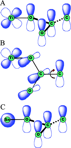 | ||
| Fig. 8 Orbital diagrams for ester-type binding to the surface of metal oxides. (A) For TiO2, the overlap of the extended π system and the Ti 3d orbitals are thought to aid in electron injection. (B) When carboxylates are rotated in such a way as to minimize orbital overlap, the injection yields are thought to suffer. (C) Similar effects are proposed for SnO2 as the Sn s orbitals have less efficient orbital mixing with the carboxylate π system. Adapted from Fig. 4 of ref. 132. | ||
Only under very acidic, non-aqueous conditions has evidence for an ester-type linkage been observed.137 Physisorption through a solvation layer has been proposed by Hester and colleagues.138 Under most conditions relevant to DSSCs, the predominant binding mode elucidated through IR studies is a carboxylate-type linkage;137 unfortunately, the data does not allow for direct identification of the surface site(s) involved in the sensitizer–semiconductor bond.132,134,137,139–141 Deacon and Phillips have tabulated vibrational data for metal-carboxylate compounds whose structures were determined crystallographically.142 An empirical relation between the energy separation of the COO asymmetric and symmetric stretches and the carboxylate–metal coordination mode was found. This same approach has been used to predict the carboxylate binding mode on the anatase TiO2 surface, presumably to TiIV sites.134,140,141 In agreement with theoretical studies, the analysis is most consistent with the carboxylate oxygens binding to separate TiIV-metal centers.134,137,140,143 Such carboxylate linkages were observed even when the binding group was originally an ester, e.g. with the deeb ligand which is 4,4′-(C2H5CO2)2-bpy. Therefore, we make no distinction between deeb and dcb throughout this review. Similarly, as the extent of deprotonation of sensitizers on the TiO2 surface is often unknown, the overall formal charge of semiconductor-bound sensitizers is often omitted.
While transition-metal compounds based on dcb ligands remain the most successful for DSSCs, an important limitation is their poor stability in water.144 Moderate stability has been reported in acidic electrolytes, but the sensitizers rapidly desorb when the pH is raised above pH ∼3.5.145 In aqueous solutions, the most stable linkages appear to be those based on phosphonate groups.144
There now exists a large body of literature on the sensitization of TiO2 by FeII-, RuII-, OsII- and ReI-polypyridyl compounds.146 There have also been some reports of sensitization by d8 compounds based on PtII, that also have MLCT-like excited states, and d10CuI compounds.147–149 Some of these results are highlighted in this review as alteration of the metal center has, in some cases, provided insights into mechanistic details of dye sensitization.
It is often tacitly assumed that the manifold of MLCT excited states observed in dilute solution or frozen glasses is unperturbed by the semiconductor surface. This assumption is often necessary as ultrafast injection precludes characterization of the excited state. However, as described in more detail below, the acceptor states in TiO2 can be widely tuned in energy by controlling the concentration of potential-determining ions at the interface. With this approach and by utilizing sensitizers that are weak photoreductants, data on MLCT excited states anchored to TiO2 are now becoming available. One interesting finding is that the proximity of the sensitizers to one another on the surface affords efficient lateral energy transfer across the semiconductor surface.150,151 Monte-Carlo simulations indicate a (30 ns)−1 energy transfer hopping rate constant at saturation surface coverage.152 There is also evidence that the ligand-field states are destabilized upon surface binding. For example, compounds of the type [cis-Ru(bpy)2(ina)2]2+, where ina is isonicotinic acid, are non-emissive in fluid solution with high quantum yields for photo-induced ligand loss, behavior that is expected for compounds with low-lying, ligand-field excited states. However, upon binding to MO2 (M = Ti or Zr) thin films, the compounds were found to be photoluminescent with temperature-dependent, excited-state lifetimes that were ∼50 ns at room temperature.54 Both static and dynamic excited-state quenching were observed as the temperature was raised providing direct evidence that the intersystem-crossing quantum yield was temperature dependent and less than unity. Interestingly, when bound to TiO2 thin films there was an inverse relation between the temperature and the quantum yield for photo-induced, interfacial electron injection, herein referred to as the ‘injection yield.’
3. Photo-induced, interfacial charge separation
The excited-state, interfacial-charge-separation mechanism shown in Fig. 1 is in fact only one of three mechanisms identified for electron injection. Said mechanisms differ by the state of the sensitizer and location of the electron that is transferred to the semiconductor: (1) the excited state, i.e.[RuIII(bpy)2(dcb−)]2+*; (2) the reduced state, i.e.[RuII(bpy)2(dcb−)]+; or (3) via a molecule-to-particle charge transfer event, i.e.RuII–CN–TiIV. An important variable for all of these sensitization mechanisms is the overlap of the molecular donor levels with the acceptor states of the semiconductor.Gerischer formulated a theory for excited-state injection into wide-bandgap semiconductors.153–155 The rate of interfacial electron transfer at an electrode surface is proportional to the overlap of occupied donor excited states with unoccupied acceptor states:
| kinj∼∫κ(E)D(E)Wdon(E) dE | (6) |
 | (7) |
A Density of states in nanocrystalline TiO2 thin films used in DSSCs
What are the density of unoccupied acceptor states, i.e. DOS, in nanocrystalline, anatase TiO2 thin films? This question remains somewhat unresolved. The classical method for determining these in the solid state is viaphotoelectron spectroscopy. Hagfeldt and co-workers have reported such data for a nanocrystalline TiO2 thin film sensitized with N3 in the presence and absence of Li+ salts, Fig. 9(a).156 This data shows a broad distribution of trap states centered at ∼1 eV below the energy of the conduction band edge (Ecb). However, it is well known that the flatband potentials of the semiconductors are very sensitive to environment. Therefore, the absolute and relative energies in vacuum may not be as relevant to a DSSC. In the field of photoelectrochemistry, the standard approach for determining the flatband potentials of semiconductor electrodes is Mott–Schottky analysis of capacitance data.157 The analysis is based on the potential-dependent capacitance of a depletion layer at the semiconductor surface, behavior that is not likely observed for ∼20 nm anatase crystals that are expected to be fully depleted near kT.18,158–165 Rothenberger and co-workers have proposed an accumulation-layer model to describe the potential distribution within the TiO2 particles at negative applied potentials.166 This model assumes that the band-edge positions remain fixed as the Fermi-energy is raised into accumulation conditions, behavior that has little literature precedence in electrolyte solutions. Nevertheless, the model provides the only literature estimates of Ecb available for these materials in organic and aqueous solvents with common electrolytes.166–170 The literature values give the impression that the nanocrystalline TiO2 thin films have a well-defined Ecb. Even if this is the case, there is a tremendous compilation of data supporting the notion that the acceptor states relevant to interfacial charge separation and recombination are more localized and are reduced more easily than literature Ecb values indicate.171–174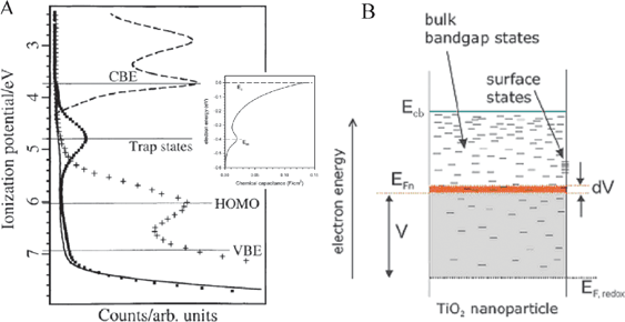 | ||
| Fig. 9 (A) The density of acceptor states, DOS, for TiO2 thin film electrodes as measured by photoelectron spectroscopy and electrochemical methods (smaller plot). The figures were scaled so as to align the energies of the (surface) deep trap states, exponential DOS near the conduction band, and conduction band edge; however, the energy differences among these states are dissimilar. Adapted from Fig. 1(b) of ref. 156 and Fig. 3 of ref. 171. (B) A diagram depicting the proposed energetic and spatial location of these same states as a function of their depth in a nanoparticle relative to the energy of the conduction band edge, Ecb, and the energy of the solution redox electrolyte, EF,redox. Adapted from Fig. 2(a) of ref. 171. | ||
Many electrochemical, photochemical, and spectroscopic studies have supported the suggestion that mesoporous, nanocrystalline TiO2 thin films possess a tailing of the DOS rather than an abrupt onset from an ideal Ecb. Determination of the precise form of these tailing states is non-trivial, however a novel computational method for determination of the absolute DOS distribution at zero Kelvin was recently reported by Bisquert and Zaban, and colleagues.172,174 Although fundamentally important, the room temperature apparent DOS distribution is more relevant to the functioning DSSC. At room temperature, this distribution is thought to have an exponential dependence on the applied voltage as determined from electrochemical techniques where Fermi-level pinning was deduced to be negligible, Fig. 9(a), inset,171,173–175 and recently by a spectroelectrochemical procedure.176 Additionally, non-exponential kinetics for excited-state electron injection can be rationalized by invoking an exponential DOS at the TiO2 surface.177–180 And by assuming said distribution is composed of bulk, intra-bandgap states, Fig. 9(b), diffusion of TiO2 electrons, TiO2(e−)s,|| and dispersive recombination kinetics can be modeled satisfactorily by employing a multiple-trapping, continuous-time random walk model.178,181–186 In addition, via these same techniques, Kavanet al., and many others since, have reported that TiO2 thin-film electrodes contain a relatively large population of deep, surface trap states at an energy located within the bandgap and prior to a significant portion of the exponential distribution.171,187–193 These states are believed to be unsaturated TiIV surface states where oxygen vacancies reside. The energetics of such states were shown to be affected by surface chelation from various molecules due to the Lewis acidic and basic characteristics of the unsaturated TiIV and surface-bound molecules, respectively.188,189,192,194
The TiO2(e−)s inferred from electrochemical measurements have spectroscopic signatures as well. As the indirect bandgap of anatase TiO2 is 3.2 eV, its ground-state UV-Vis absorption spectrum consists of a fundamental absorption edge at ∼385 nm and, in some cases, an Urbach tail at longer wavelengths.195–198 The features observed for TiO2(e−)s in mesoporous, nanocrystalline TiO2 (anatase) thin-film electrodes consist of a minor Burnstein–Moss shift, i.e. a blue shift in the fundamental absorption edge,199,200 and a gradual rise in absorbance that tails to the near-IR,201,202 and peaks at ∼1350 nm.203 The extinction coefficient for the broad, featureless, visible-near-IR absorbance ranged from 640 to 1300 M−1 cm−1 at 700 to 800 nm based on choice of solvent and electrolyte.166,187,204,205 Similar features were present upon electrochemical bias of a single-crystal TiO2 (rutile) electrode to form TiO2(e−)s: a broad near-IR spectroscopic feature that peaked at 1500 nm.206 As evidenced by spectroelectrochemical measurements, in addition to the current required to generate the “typical” TiO2(e−) absorption features, an additional current pre-peak has been observed that is often largest in aqueous electrolyte, Fig. 10(a).187,189,190 This has been ascribed to filling deep, surface trap states. It was determined that ∼12 of these surface states existed per 12 nm nanocrystallite and that they exhibited an absorption peak centered at ∼400 nm (ε400 nm = ∼1900 M−1 cm−1), Fig. 10(b).187 Additionally, a new, broad absorption peak centered at ∼750 nm was observed (ε700nm = ∼2200–2800 M−1 cm−1), after passing >40 mC cm−2 (∼100 TiO2(e−)/particle) in the presence of cations with large charge-to-radius ratios, i.e.Li+, Na+, in acetonitrile or strongly basic aqueous electrolytes, Fig. 10(c).205,207,208 This feature is indicative of small cation intercalation into the anatase lattice to form new phases.156,190,209–215Li+ intercalation into highly reduced anatase TiO2 is known to form Li0.5TiO2 phases,216,217 however such phases are not expected to be relevant to operational DSSCs.
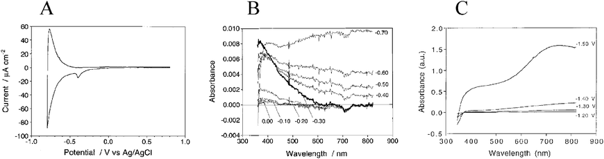 | ||
| Fig. 10 (A) A cyclic voltammogram of a TiO2 thin-film electrode in aqueous electrolyte. The large, reversible peak was indicative of filling and emptying the TiO2 DOS whereas the smaller pre-peak, present during the cathodic scan only, was assigned to the filling of deep trap states. Taken from Fig. 3(a) of ref. 187. (B) The absorption spectra of these biased electrodes illustrated the spectroscopic features associated with occupation of deep trap states, at −0.30 V and in bold, and formation of TiO2(e−)s, at −0.70 V. Taken from Fig. 2 of ref. 187. (C) The absorption spectra of a thin film electrode in LiClO4 acetonitrile electrolyte biased to −1.50 V where formation of a new species, i.e. Li0.5TiO2 phases, was clearly evident near 750 nm. Taken from Fig. 3(a) of ref 205. | ||
The TiO2(e−) states above are often described as shallow trap states and not entirely free conduction band electrons as their absorption would tail much farther into the IR,218,219 they exhibit a sharp electron paramagnetic resonance (EPR) spectrum at 77 K,220–222 and their apparent DOS follows an exponential distribution156,171–175,177–180 with a non-ideality factor often greater than one.171,178,183–185,223,224 An apparent exponential DOS distribution is also expected from theory for an ideal intrinsic semiconductor even though the actual underlying DOS distribution follows a power-law relationship with energy.225 However, the presence of a non-ideality factor unequal to unity is often attributed to a large concentration of trap states218,219 Notwithstanding, using time-resolved infrared (TRIR) spectroscopy it was shown that the transient absorption features of TiO2(e−)s in TiO2 and TiO2–Pt colloids can be modeled as a function of the wavenumber to the −1.5 power, indicative of free conduction band electrons.203,226 As electrons are thought to trap in TiO2 at coordinatively unsaturated TiIV atoms within a picosecond it was proposed that trapped electron thermalization to the conduction band may be possible at room temperature.
A final comment with regard to the semiconductor DOS is that they are not singular material parameters. The most well-known example is the nearly Nernstian shift, i.e. 59 mV/pH unit, in aqueous solution over the pH range H0 = −8 to H− = +23 due to protonation/deprotonation of surface titanol groups on TiO2.166,169,227,228 It has also been known for quite some time that the flatband (and conduction band edge) potential of mesoporous, nanocrystalline TiO2 (anatase) can be widely tuned by the presence of cations in non-aqueous supporting electrolyte. This affect is greatest with cations possessing a large charge-to-radius ratio in the order Mg2+ > Li+ > Na+ > K+ > TBA+.167,168 For example, Ecb has been reported to be −1.0 V vs.SCE (−0.76 V vs.NHE229) in 0.1 M LiClO4 acetonitrile electrolyte and ∼−2.0 V (−1.76 V) when Li+ was replaced by TBA+. The direction of the band-edge shifts has been confirmed by excited-state quenching data described below. Interestingly, this same order has been observed for the equilibrium constants for cation adsorption onto TiO2 in aqueous solutions230–233 and an electrolyte’s “drying effect,” ionic association constant in aprotic solvents, and hydroxide association constant.234 Although this shift is non-Nernstian, the behavior has been shown to be logarithmic in LiClO4 activity in acetonitrile and other aprotic mixed solvent systems.167,168 Similar behavior was not observed in protic solvents hypothesized to be due to selective solvation of Li+ by the protic solvent molecules.167,168 In TBA+ salts the flatband potential has been shown to depend logarithmically on the auto-ionization/autoprotolysis constant of the solvent.167,168 Thus, most likely, the large variations in Ecb (>1 V) induced by the above ‘potential determining’ ions can be wholly explained by cation-coupled reduction potentials for TiO2 acceptor states, due to surface adsorption and/or intercalation into the anatase lattice. This same cation-dependent shift in Ecb can be used to promote photo-induced electron injection from surface-bound sensitizers.
B Ultrafast, excited-state electron injection
After light absorption, the MLCT excited state of the sensitizer may inject an electron into the anatase nanocrystallite, a process also referred to as interfacial charge separation. For sensitizers like N3, light absorption formally promotes an electron from the metal center to a dcb ligand that is directly bound to the semiconductor surface. Therefore, excited-state charge separation occurs from the π* orbitals of the organic ligand to the acceptor states in TiO2, Fig. 8(b). There is now an overwhelming body of data that indicates that such charge separation occurs on a femto- to pico-second time scale. Experimentally, ultrafast spectroscopists have all found that excited-state electron injection into TiO2 is non-exponential, behavior attributed to the surface heterogeneity of TiO2 and its DOS, distributions of sensitizer binding modes, strengths, and interactions, and multiple ultrafast injection processes occurring from various states in the thermal relaxation pathway, i.e. Franck–Condon singlet injection, internally converted singlet injection, intersystem crossing to the triplet state(s) followed by injection. This has been thoroughly reviewed for both organic and transition-metal coordination compounds bound to semiconductor metal oxides.102,115,119 While the explanations given to rationalize the complex kinetics observed for excited-state injection for RuII sensitizers are often reasonable, satisfactory mechanistic models are still lacking.It has been suggested that ultrafast, interfacial charge separation, following light absorption, does not always occur from the thexi state but rather often from the initial, Franck–Condon excited state. Evidence for room-temperature injection occurring with a lifetime faster than a molecular vibration, i.e. kBT/h = ∼1.6 × 10⁻¹³ s = 160 fs,235,236 eludes to this phenomenon.102–119 This would imply that injection is occurring before thermal relaxation of the molecular excited state.
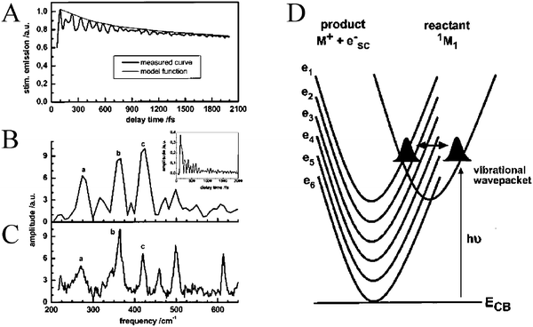 | ||
| Fig. 11 (A) An ultrafast, time-resolved, single-wavelength absorption difference spectrum for perylene/TiO2 displaying periodic beats. The Fourier transform, (B), of the periodic beats, (inset), effectively reproduced the normal modes of perylene, (C). (D) A schematic depicting the model used to rationalize the empirical data; periodic crossing of the molecular vibrational wavepacket with the TiO2 DOS. Taken from Fig. 5 and 10, respectively of ref. 244. | ||
The quantitative, ultrafast excited-state electron injection reported for N3/TiO2 under ultrahigh-vacuum conditions was not always observed when the sensitized thin films were placed in organic solvents or electrolytes. Under such conditions, injection was non-exponential and occurred on the femtosecond to hundreds-of-picoseconds time scale. For N3 and porphyrin-based sensitizers, Durrant and co-workers found that a sum of three exponentials was required to fit the injection data, including an ultrafast <100 fs component.117,118 Interestingly, the rate constants for bpy- and porphyrin-based dyes were similar. These same authors later found that N719—the dianion salt of N3 with TBA+ counterions—had a 30-fold slower rate of injection as compared to N3.245 After performing multiple washings of the N3/TiO2 films in neat ethanol the injection rates were similar to that of N719/TiO2 films. It was suggested that the labile protons from the carboxylic acid binding groups of N3 had lowered the Ecb and promoted more favorable energetics for injection. To control this variable Lian and co-workers pre-treated N3/TiO2 thin films for one day in aqueous buffer solutions at pH 2, 4, 6, or 8.103 After removing weakly bound and desorbed sensitizers, the biphasic kinetics and injection yields were found to be pH dependent. As the pH was raised from 2 to 8, there was a decrease in the rate of the slower component to injection, the ratio of the faster-to-slower components to injection, and the injection yield. Such behavior is consistent with the expected Nernstian shift of Ecb towards the vacuum level as the pH is raised.
Grätzel and co-workers reported that the slower picosecond components for excited-state electron injection could be removed by employing a low concentration or sonicated dying solution or a lower surface-coverage thin film.246,247 Under such conditions, only an ultrafast component (<20 fs) for injection remained. In support of this, Piotrowiak and co-workers found that dialysis of sensitized TiO2 colloids resulted in much shorter excited-state lifetimes as measured by time-correlated single photon counting.248 However, in this case multi-exponential kinetics were required to adequately fit the observed data.
Lian and co-workers found that excited-state electron injection into TiO2 was biphasic for three [cis-Ru(dcb)2(X)2]0,0,2+ compounds (X = SCN−, X = NC−, or (X)2 = dcb) and fit a two-state model.103 The rate of the slower component was directly related to the sensitizer excited-state reduction potential while the relative magnitude showed the opposite trend. No noticeable changes were apparent for the fast component within the time resolution of the measurement, i.e.∼200 fs. With Re(dcb)CO3Cl/TiO2 it was suggested that ultrafast injection (<50 fs) was from a vibrationally ‘hot’ state.103–106 As measured by femtosecond TRIR spectroscopy, the CO stretching band in the excited state red-shifted by 10 cm−1 over 10 ps. The difference in rate constants implied that injection occurred before thermal electron relaxation and reorganization of the inner-sphere ligand environment. This same group reported the injection dependence for carboxylic acidversusphosphonic acid linkers with Re(dmb-X2)CO3Cl sensitizers, where dmb is 4,4′-dimethyl-bpy (X = COOH or PO3H2).116 The sensitizer with X = PO3H2 resulted in faster injection which was in conflict with previous findings employing organic sensitizers.108 However, the experimental data was supported by DFT calculations on the anionic versions of the sensitizers showing that there was a stronger electronic coupling between the dmb-X2 and TiIV-metal centers when bound through phosphonate linkages.116 Additionally, solvent-dependent injection rates were studied using Re(dcb)CO3Cl sensitizers.249 It was found that the rate of the slow, picosecond component for injection decreased in the order water (pH 2) > MeOH ≈ EtOH > water (pH 8) > DMF which could be expected based on the proposed Ecb for TiO2 and electron transfer in the Marcus normal region. However, changes were not as large as expected due to trace water adsorbate whose presence was verified by FTIR.
McCusker and co-workers found excitation wavelength-dependent, tri-exponential kinetics for N3/TiO2, cis-Ru(dcb)2(CN)2/TiO2, and their osmium analogues.112 For the RuII-based sensitizers, excitation at shorter wavelengths resulted in a larger amplitude femtosecond component, assigned to electron injection from the 1MLCT excited state, and thus a smaller picosecond amplitude, assigned to injection from the 3MLCT excited state. On the picosecond-time scale, 3MLCT components were much more dominant for osmium analogues where the spin–orbit coupling was larger. For all sensitizers studied, the rate of the picosecond component was found to be directly related to the sensitizer excited-state reduction potential, Eo(RuIII/II*), consistent with electron injection from the thexi state.
At about the same time, Sundström and co-workers reported stimulated emission from the initially formed, singlet excited state of N3 with a ∼70 and ∼30 fs half rise-time in solution and on TiO2, respectively.107,111 These time scales were similar to those measured by femtosecond transient absorption spectroscopy for intersystem crossing, Fig. 12(b).107,111,114 The branching ratio for electron injection from the 1MLCT state and intersystem crossing to the 3MLCT state resulted in time constants of ∼50 and ∼75 fs for each process, respectively. Excitation into the low-energy shoulder of N3's absorption spectrum was shown to directly populate N3's 3MLCT manifold both in solution (τ = ∼70 fs) and on TiO2. It was also shown that injection became slower and less efficient, i.e. from ∼100% to ∼50%, as the excitation light was shifted towards longer wavelengths, Fig. 12(b). This was postulated to be due to injection from a manifold of 3MLCT excited states. Similar findings have been observed for [Ru(bpy)2(dcb)]2+ on SnO2 but resulting in slightly larger half-times,250 behavior that is consistent with Goodenough’s hypothesis.132 These same authors found that by varying the method of TiO2 film preparation, both rate constants for the biphasic injection kinetics for N3* into TiO2 were directly related to the degree of TiO2 crystallinity.110 Similar effects have been observed with organic sensitizers.251,252
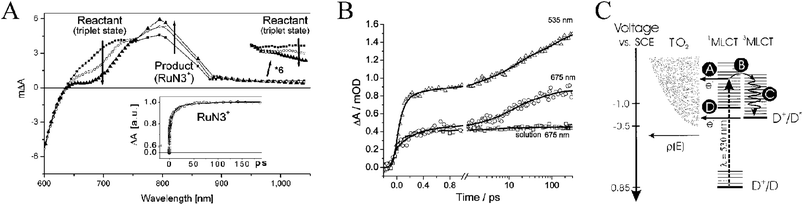 | ||
| Fig. 12 (A) Picosecond transient absorption difference spectra for N3/TiO2 where changes due to 3MLCT excited-state injection are noted. Taken from Fig. 2 of ref. 107. (B) Time-resolved, single-wavelength absorption difference spectra for N3 and N3/TiO2 demonstrating relaxation within the triplet-character manifold of states on the picosecond time scale. Excitation wavelengths are indicated on the figure. Taken from Fig. 4 of ref. 114. (C) A schematic depicting the possible interfacial, excited-state processes: (a) ultrafast, ‘hot’ injection; (b) intersystem crossing; (c) vibrational relaxation; and (d) slower thexi-state injection. Taken from Fig. 9 of ref. 111. | ||
As mentioned previously, spin arguments with RuII and OsII sensitizers are complicated by spin–orbit coupling that effectively mixes the spin states, no longer making spin a good quantum number. With organic sensitizers this is not the case and well-defined singlet and triplet states have been shown to sensitize TiO2. With a TiIV-phthalocyanine sensitizer anchored to TiO2via an axial 3,4,-dihydroxybenzoic acid ligand, wavelength-dependent injection yields were apparent.253 Although such behavior could have been attributed to ‘hot’ injection, this was not thought to be the case here. The rate constants for excited-state injection from the equilibrated singlet and triplet excited states were proposed to be different. This state-selective injection was assigned to efficient kinetic competition between injection from the S2 excited state (from excitation into the Soret band) and internal conversion/vibrational relaxation of this state to the lower lying S1 state (that can be directly populated with excitation into the Q bands).
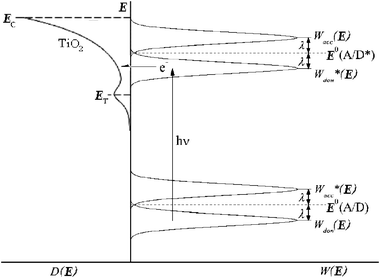 | ||
| Fig. 13 A Gerischer Diagram illustrating excited-state electron injection from surface-bound sensitizers into the DOS of the TiO2 nanocrystallites. E is the electrochemical potential of the conduction band edge (Ecb), of the deep trap states (ET), and of the sensitizer at standard-state conditions (E0(A/D) and E0(A/D*), for the ground and thexi states, respectively). D(E) is the TiO2 DOS, Wdon(E) and Wdon*(E) are the sensitizer donor distribution functions of the ground and thexi states, Wacc(E) and Wacc*(E) are the sensitizer acceptor distribution functions, and λ is the reorganization energy. Adapted from Fig. 3 of ref. 171 and Fig. 3(a) of ref. 119. | ||
We have shown that the excited state of Ru(bpy)2(dcb)/TiO2 thin films immersed in acetonitrile exhibit both static and dynamic quenching when Li+ is introduced into solution.254 This was ascribed to photo-induced electron injection into TiO2 acceptor states where said states become thermodynamically accessible due to the positive cation-induced shift of the DOS. This was further supported by the monotonic and somewhat linear increase in both PLI/PLIo and injection yield with the logarithmic concentration of Li+ (PLI is photoluminescence intensity). The trend for such behavior was linear in the charge-to-radius ratio of the 2 mM cation employed in the order Ca2+ > Ba2+≈ Sr2+ > Li+ > Na+ > K+ > Rb+≈ Cs+≈ TBA+, and smallest for neat acetonitrile.
As mentioned previously, in the absence of such external cations the flatband potential has been reported to scale logarithmically with the solution auto-ionization constant.167,168 This implies that proton activity determines the potential of the TiO2 DOS in these neat solvents. Thus, a strategy to introduce cations with a large charge-to-radius ratio into non-aqueous electrolytes was employed: acid- and base-pretreatment of TiO2 thin films using H2SO4, HCl, or HClO4 and NaOH, respectively.137 It was shown that when [Ru(bpy)2(deeb)]2+ sensitizers were bound to acid pre-treated TiO2 films they bound as the acid form, i.e.–COOH, and injected electrons much better than base pre-treated films, which bound as the carboxylate form, i.e.–COO−. In fact, injection yields in neat acetonitrile and IPCEs in TBAI/I2 electrolyte were <10% for pH >3 pre-treatment while for pH <2.5 pre-treatment injection yields were >80%. (It is of note that the point-of-zero charge of TiO2 is ∼5–6255–258 while the pKa of the sensitizer carboxylic acid groups are 1.75 and 2.80.)259 Upon addition of LiClO4 to base pre-treated films, injection yields increased significantly; for acid pre-treated films, most of the dyes desorbed.
All of the previously described photo-induced electron injection studies were performed on equilibrated systems under open-circuit conditions. It is important to quantify interfacial charge separation under short-circuit conditions—when the system is initially at a steady state—and to specifically quantify the effect(s) TiO2(e−)s have on excited-state injection. The first such report studied the bias-dependence on the injection yield from a photoexcited Ru(dcb)3/TiO2 thin-film electrode in a pH 3, 0.2 M LiClO4 aqueous electrolyte.158 Upon reverse bias or near open-circuit conditions, the injection yield was essentially unity. However, as the electrode was biased in the forward direction, closer to the operational power point of the electrode, the injection yield dropped to ∼0.5, Fig. 14. This was ascribed to the filling of the DOS in TiO2 leading to decreased injection and an increase in PLI. Similar behavior was observed on sensitized SnO2electrodes.260 A complication in these studies is that forward bias can result in desorption of the sensitizers from the semiconductor surface, which will by itself lower injection yields and increase the PLI.261
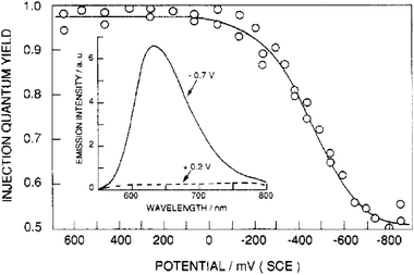 | ||
| Fig. 14 The quantum yield of excited-state electron injection from surface-bound Ru(dcb)32+ into TiO2 as a function of electrochemical applied bias. Inset: The photoluminescence spectra of Ru(dcb)3/TiO2 thin film electrodes at the indicated potentials. Taken from Fig. 8 of ref. 158. | ||
A seven-fold increase in the half-time for excited-state electron injection from fully deprotonated N3/TiO2 in acetonitrile was obtained by omission of Li+ from the solution.262 Biasing the sensitized electrode to −700 mV vs.Ag/AgCl, the most negative bias where desorption/degradation did not occur, resulted in the same injection yield on the longest time scales studied, 600 ps, but with significant attenuation of the fast component to injection. The half-times for injection were 25-fold slower at this applied bias and could be modeled by non-adiabatic electron transfer theory where, prior to injection, thermal equilibrium of the excited state was assumed. Since up to 40% of the injection occurred on the sub-molecular vibration time scale, i.e.∼160 fs, the injection kinetics were most likely modeled under conditions where the assumption was valid.
| k = koexp[−βx] | (8) |
An early study demonstrated that efficient excited-state electron injection did occur from sensitizers of the general type Ru(dmb)2(L)2+, where L contained unconjugated –(CH2)x– linkers between the Ru-chelating bpy moiety and one carboxylic acid group.72 A more systematic study was later reported using three Re(bpy(CH2)2n(COOH)2)CO3Cl (n = 0, 1, 3) sensitizers where it was shown that ultrafast injection into TiO2 did not occur when electronic coupling between the surface-bound ligand and the TiO2 surface was removed by unconjugated methylene spacers, i.e. when n = 1 or 3.104,105 For the same two sensitizers, the slower picosecond injection process could be successfully fit to a stretched exponential and the distance dependence of the injection rate could be qualitatively modeled by eqn (8) using β = 1.2 for each C–C bond, indicative of nonadiabatic electron transfer. The >200-fold increase in injection rate from n = 1 to n = 0 could not be fit to such a model and was explained as adiabatic electron transfer due to a greatly increased strong electronic coupling from the lack of an unconjugated spacer moiety, Fig. 15. Detailed comparison of the n = 0 with the n = 1 or 3 compounds were complicated by the fact that the n = 0 compound had significantly different photophysical and redox properties.
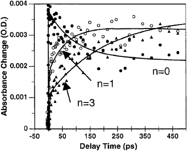 | ||
| Fig. 15 Time-resolved, single-wavelength absorption difference spectra for Re(bpy(CH2)2n(COOH)2)CO3Cl/TiO2 (n = 0, 1, 3) illustrating that the rate of injection was inversely related to n. Taken from Fig. 9 of ref. 104. | ||
The distance dependence of excited-state electron injection was also explored using RuII sensitizers that contained a bpy ligand derivatized with a conjugated oligo(xylylene) linker and bound to TiO2via an ethynylcarboxyphenyl group.267 A series of three compounds, with zero, one, or two linkers, was employed. A mere two-fold difference in injection rate constant was inferred by the difference in integrated PL spectra of the dyes in solution and on TiO2. The lack of the expected large differences was proposed to result from the flexibility of the one-carboxyl sensitizer attachment, that allowed proximity of the RuII-metal center and the TiO2 surface in all three cases. In a related study, sub-picosecond injection was observed for tripodal, Ru(bpy)32+-based sensitizers with an oligo(phenyleneethynylene) linker covalently bound to a tricarboxyphenyladamantane base calculated to have Ru–TiO2 distances over 24 Å.268–270 This study did not systematically show that rates vary with distance but did provide strong evidence that the distance dependence on injection rate was not large.
With three phosphonated, ‘black dye’-like compounds of the form [Ru(4′-PO3(Ph)n-tpy)(NCS)3]3− (n = 0, 1, 2) the distance-dependence of excited-state electron injection through conjugated linkers was studied.271 Femtosecond pump–probe transient absorption measurements revealed that the rate of each phase of an observed biphasic injection process was dependent on distance. The fast picosecond component fit nicely to an exponential distance-dependent model, eqn (8), with dampening factor, β = 0.19 Å−1, while the slower component for injection was assumed to be due to injection from loosely bound or aggregated dyes. As this dampening factor was much smaller than typical values obtained for donor–bridge–acceptor systems in solution, it was proposed that nuclear reorganization played a negligible role in injection, a hypothesis supported by DFT calculations.
The distance-dependence was investigated by yet another means using the sensitizer lacking phenylene bridges, i.e. n = 0; a core-shell architecture272–276 was employed with Al2O3 shells varying from 0.6–6 nm in thickness conformally deposited on TiO2 prior to thin film preparation, Fig. 16(a).271 The insulating shell required tunneling for almost all excited-state injection. As tunneling is not only a factor of distance but barrier height as well, this architecture allowed solely the distance to be altered. Neglecting ultrafast injection, which was assumed to be from dyes adsorbed directly onto TiO2 from small holes in the Al2O3, it was shown that the picosecond biphasic nature of injection resulted in β = 0.11 Å−1 and 0.04 Å−1 for the fast and slow components, respectively, Fig. 16(b). As the barrier to the conduction band of bulk, crystalline Al2O3 is very large, dampening factors over an order-of-magnitude larger were expected. It was proposed that the electronic structure of thin alumina layers differed from that of bulk Al2O3.277
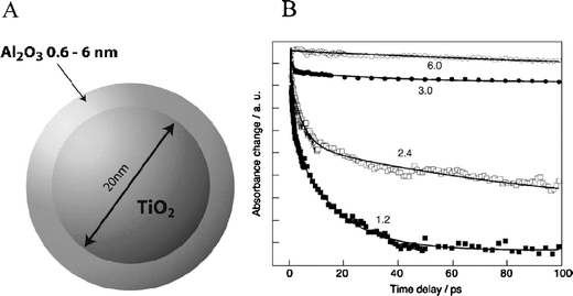 | ||
| Fig. 16 (A) A diagram of a TiO2/Al2O3 core-shell nanoparticle. (B) Time-resolved, single-wavelength absorption difference spectra for Ru(4′-PO32−-tpy)(NCS)3/TiO2 thin films illustrating that the rate of injection was inversely related to the size of the Al2O3 overlayer. Al2O3 overlayer thickness in nanometers are shown. Taken from Fig. 5 and 6, respectively, of ref. 271. | ||
Using three rigid-rod, Ru(bpy)32+-based compounds containing a conjugated bpy ligand derivatized with an oligo(phenyleneethynylene) linker and anchored to TiO2via a dicarboxyphenyl group the distance dependence of excited-state electron injection was studied, Fig. 17(a).278 It was found that a monotonic decrease in injection rate occurred as the number of linkers was increased. However, this dependence only resulted in a dampening factor, β = 0.04 Å−1, for both the slow and fast picosecond components, whereas a similar study on SnO2 resulted in a value of ∼0.8 Å−1,279 and theoretical values were >0.4 Å−1. Although this small distance dependence agrees rather well with the conclusions from the phosphonated, ‘black dye’-like compounds, these results were further complicated by the lack of an expected similar trend in injection yields, where the middle-length spacer was found to inject best, Fig. 17(b).
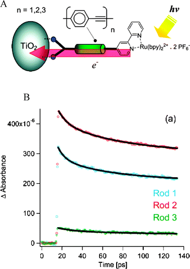 | ||
| Fig. 17 (A) A diagram of a rigid-rod, Ru(bpy)32+-based sensitizer bound to a TiO2 nanocrystallite. (B) Time-resolved, single-wavelength absorption difference spectra of these TiO2-bound sensitizers containing rods of oligo(phenyleneethynylene) linkers (n = 1, 2, 3). Although the injection yields were not distance-dependent, the rates were inversely related to n. Taken from cover artwork and Fig. 3A, respectively, of ref. 278. | ||
The observation of efficient and rapid excited-state electron injection through saturated and unsaturated spacers raises the question of whether the MLCT excited state need be localized on a ligand that is directly attached to the semiconductor surface. In other words, could the surface linker be on a non-chromophoric ligand? An early test of this was performed with a bimetallic ReI(dcb)CO3–L–RuII(bpy)2(CN) (L = CN− or NC−) compound.280 Long-wavelength excitation selectively promoted an electron from the RuII-metal center to a bpy ligand that was not anchored to the semiconductor surface, yet still resulted in a large photocurrent in regenerative DSSCs.
The dcb ligand is structurally the same as two ina ligands connected in the 2 and 2′ positions. The extra covalent bond in the dcb ligand increases the overall conjugation and thus lowers its LUMO energy. Using a comparative study of two heteroleptic RuII compounds, one with a dcb ligand and the other with two ina ligands, the effect of remote versus adjacent excited-state electron injection was directly studied, Fig. 18.281 Both compounds exhibited a similar pH-dependent injection at pH >2 even though the thexi state of the latter compound contained an electron localized on a ligand that was not bound to the TiO2 surface. The observations of efficient injection from sensitizers with an ina ligand has been observed for Re(bpy)CO3(ina)+ as well.282
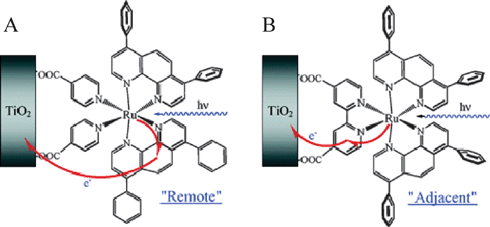 | ||
| Fig. 18 A schematic illustrating two different injection schemes depending on the surface-bound ligands: (A) Remote excited-state injection pathway for cis-Ru(dpp)2(ina)2/TiO2, where dpp is 4,7-diphenylphenanthroline, due to excited-state localization on a dpp ligand. (B) Adjacent excited-state injection pathway for Ru(dpp)2(dcb)/TiO2 as the excited state is localized on the surface-bound dcb ligand. Taken from cover artwork of ref. 281. | ||
The ina ligand, and substituted analogues, can also be coordinated to axial sites in porphyrinic macrocycles. A RuII-phthalocyanine sensitizer with axial 3,4-dicarboxylic acid-pyridine was employed.283 The pyridine derivative allowed for surface binding of the sensitizer to TiO2 however the major near IR–visible light absorption features were due to intraligand π→π* transitions that were localized on the phthalocyaninato ligand. Quasi-monochromatic light excitation resulted in excited-state electron injection into TiO2 with a maximum IPCE > 60%, due entirely to remote injection. Similar remote injection results have been obtained for similar π→π* transition molecules: a TiIV phthalocyanine with a 3,4-dihydroxybenzoic acid surface-binding ligand and other RuII phthalocyanines with a 4-carboxylic acid-pyridine surface-binding ligand.253,284,285
In addition to the ultrafast, ‘hot’ injection observed in high vacuum, solvents, and electrolytes, there are in fact a few literature observations that indicate that photo-induced ‘hot’-electron injection occurs in DSSCs. The first example was with cis-Fe(dcb)2(CN)2/TiO2 that exhibited a band-selective photocurrent action spectrum.286 Although the photocurrent efficiency was poor at all excitation wavelengths (<10%), there was over a five-fold increase in the absorbed-photon-to-current efficiency (APCE), or internal quantum efficiency, when the higher-energy absorption band was excited. This behavior was attributed to band-selective injection yields occurring when injection was not from the thexi state. Thus, this further supported the interfacial, ‘hot’-injection mechanism. Similar behavior was reported for cis-Ru(dcbq)2(NCS)2/TiO2, where dcbq is 4,4′-dicarboxylic acid-2,2′-biquinoline.287 It was shown that the APCE was wavelength-dependent with the lower-energy band exhibiting smaller APCEs and rationalized as injection from this band being thermodynamically unfavorable. This is indicative of ‘hot’-injection processes from both bands with additional thexi-state injection from the higher energy band only. The hypothesis was tested with SnO2 thin films, whose Ecb is ∼500 mV more positive than that of TiO2. The photocurrent action spectrum better traced the absorptance spectrum as the APCE was no longer wavelength dependent. The third example we are aware of was reported by Heimer and co-workers who also observed APCEs that were wavelength dependent on TiO2, but not on SnO2, with N3-like derivatives with the carboxylic acid groups present in the 5 and 5′ positions.288
An alternative approach for quantifying ‘hot’-electron injection is to measure the injection yields as a function of the excitation wavelength. Moser and Grätzel first reported studies of this type.289 For N3/TiO2, the nanosecond injection yields were quantitative and wavelength independent. However, when N3 was anchored to Nb2O5, who’s Ecb is more difficult to reduce, wavelength-dependent injection yields were observed that decreased as the excitation wavelength increased. When the sensitizer was changed to cis-Ru(2,6-bis(1′-methylbenzimidazol-2′-yl)pyridine)(dcbq)(NCS)2, the injection yields were found to be strongly wavelength dependent. The dcbq ligands have low-lying π* LUMO energies, too low for the thexi state of the sensitizer to inject an electron into TiO2. Thus, ‘hot’ injection from an upper vibrational excited state was, without-a-doubt, occurring. Therefore, wavelength-dependent injection yields measured on nanosecond time scales are a signature of injection from upper, or ‘hot’, excited states.
We have recently observed similar behavior with RuII-ammine sensitizers.290 These compounds have low-lying, ligand-field states and, in some regards, have excited-state properties more similar to FeII compounds than Ru(bpy)32+. Wavelength-dependent injection yields were observed for Ru(NH3)5(ina)/TiO2 with blue-light excitation giving almost twice the injection yield as with green light, Fig. 19. Interestingly, with the tetra-ammine compounds, Ru(NH3)4(dcb)/TiO2, the injection yields were also wavelength dependent and were sensitive to isotopic substitution of the ammines. The injection yields were about 30% larger for ND3 than NH3 at all excitation wavelengths studied, data that is consistent with ‘hot’-electron injection.
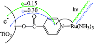 | ||
| Fig. 19 A schematic illustrating excitation wavelength-dependent injection yields for Ru(NH3)5(ina)/TiO2, i.e. 15% with 532 nm and 30% with 416 nm. Taken from cover artwork of ref. 290. | ||
There is now compelling evidence that charge separation from an MLCT excited state into TiO2 can occur faster than vibrational relaxation. The question of whether this is necessary or useful has arisen. The injected electrons are expected to trap at coordinatively unsaturated TiIV sites within a picosecond.291–295 If the electron could be collected in an external circuit prior to trapping, energy that would otherwise be lost to phonon creation could be harvested. This would allow for 1 sun, AM1.5 light-to-electrical power conversion efficiencies over the single-junction Shockley–Queisser limit of 31%296 and up to the ‘hot’-injection-limited efficiency of 66%.297 Thus, ‘hot’ injection is the first step towards achieving single junction, solar light-to-electrical power conversion efficiencies greater than 31%. However, should wave-packet dephasing108,298 accompany photo-induced electron transfer from the sensitizer to TiO2 acceptor states, ‘hot’-electron capture may be impossible. Willig et al. have time-resolved such thermal relaxation in TiO2 to picoseconds.243 The dephasing theory implies that electron transfer from the electronic wave packet in TiO2, representing the initially formed ‘hot’ electron, to a point contact is virtually impossible.109,243,244 It is thought that over time the wave packet expands throughout the film and that elastic and inelastic scattering events alter the momentum as well as the electronic and vibrational energy of the electron. Thus, most often this cooled state would reach the interface for collection or reactivity. The realization of ultrafast electron transferfrom/through the semiconductor was proposed to be feasible only under a specific and unlikely distribution of ‘hot’ electrons. Therefore, even if the excess energy is not lost through vibrational relaxation of the excited state of the sensitizers, it will most likely be lost to phonon creation on the other side of the interface.
If the TiO2 DOS lie above the excited-state reduction potential of the sensitizer it could be possible to drive an electron-transfer reaction that would be thermodynamically unfavorable from the thexi state, Fig. 20. Such a process was recently realized with heteroleptic sensitizers possessing the previously mentioned dcbq ligands, such as [Ru(bpy)2(dcbq)]2+.135,299 In this case, the acceptor was a ground-state sensitizer. The interfacial energetics were such that Ecb/DOS were more negative than Eo(RuII/+) and Eo(RuIII/II*). Therefore after ‘hot’-electron injection, resulting in a TiO2(e−) and RuIII, the TiO2(e−) could recombine with the oxidized sensitizer or reduce another surface-bound sensitizer to form RuIII/TiO2/Ru+. Using nanosecond transient absorption spectroscopy, spectral evidence for the allowed processes in Fig. 20 and wavelength-dependent injection yields lead to the conclusion that ‘hot’ injection was occurring with this compound. The conclusion that formation of RuIII/TiO2/Ru+ is mediated by the TiO2 DOS was supported by the fact that there was insufficient free energy stored in the thexi state of the sensitizer to reduce the acceptor. Thus, the proposed mechanism was that ‘hot’ injection was followed by reduction of a TiO2-bound acceptor. This serves as a proof-of-principle example and suggests that ‘hot’ injection can be used to drive ‘uphill’ redox reactions of relevance to exceeding the Shockley–Queisser limit.
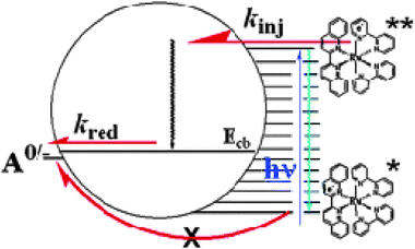 | ||
| Fig. 20 A schematic illustrating that excited-state electron injection and subsequent reduction of a co-bound molecular acceptor, A, was only thermodynamically possible if injection occurred from the initial, Franck–Condon excited state and not the thexi state. Formation of A− after pulsed-laser light excitation of Ru(bpy)2(dcbq)/TiO2 was shown to be due to ‘hot’ electron injection followed by TiO2-mediated electron transport to the acceptor. Taken from cover artwork of ref. 135. | ||
C Metal-to-particle charge transfer
There is another mechanism of photo-induced electron injection that has been observed for metal-cyano compounds anchored to TiO2. This mechanism has been termed metal-to-particle charge transfer (MPCT). This is apparent based on the observations that: (a) when said compounds are anchored to TiO2 a new absorption band is formed that was not present in fluid solution and (b) light excitation into said absorption band results in immediate formation of TiO2(e−)/S+. An interesting feature of such sensitizers is that, by definition, the injection yield is unity as light absorption and electron transfer to TiO2 are one in the same process. This is in contrast to injection from MLCT excited states described above whose injection efficiency has been shown to be a function of the pH, ionic strength, excitation wavelength, and temperature.300MPCT absorption bands were observed for the first time upon binding M(CN)xn+ complexes to TiO2 nanocrystallites (M = Fe, Ru, Os, Re, Mo, W).301,302 Some of these adducts extended the visible light photoresponse of TiO2 beyond 700 nm. Hupp et al. discovered that the resonance Raman spectrum of Fe(CN)6/TiO2 colloids exhibited the coupling of ten vibrational modes to MPCT, three of which were surface modes.303,304 Jortner and colleagues have previously described an applicable theoretical model for describing such multimode electron transfer,305–310 however the coupling of multiple surface modes to interfacial electron transfer was unprecedented experimentally.FeII-based coordination compounds containing both MPCT and MLCT bands of the type [Fe(LL)(CN)4]2− were studied, where LL = bpy, dmb, or 4,4′-diphenyl-bpy. It was shown that the MLCT absorption bands were solvatochromic whereas the MPCT bands were not.77,311 In light of this and with electrochemical results indicating that Eo(FeIII/II) did shift with solvent, it was suggested that the TiO2 DOS shifted as well and in a concerted fashion. There exists a precedence for molecular and TiO2reduction potentials shifting in concert when the molecule is poised within the ionic double layer, i.e. Helmholtz and diffuse layers.312,313 Using an [Fe(bpy)(CN)4]2− sensitizer, the possibility for a dual-mechanism of sensitization was explored, Fig. 21.311 Excitation directly into the MPCT band would inherently result in an injection yield of unity and be independent of the experimental conditions. In acetonitrile solutions it was shown that the injection yield could be reversibly tuned with the addition of LiClO4; clearly this was not a result of a MPCT transition as the UV-Vis absorption spectrum was largely independent of electrolyte. Thus, not only was direct MPCT present in this system, but less-efficient electron injection from a proximal MLCT excited state was apparent as well.
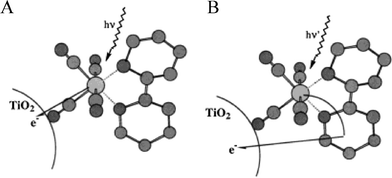 | ||
| Fig. 21 Ball-and-stick models for Fe(bpy)(CN)4/TiO2 portraying two possible mechanisms for photo-induced electron injection into TiO2: (A) direct, metal-to-particle charge transfer (MPCT) sensitization; (B) sensitization by means of a metal-to-ligand charge-transfer (MLCT) excitation followed by excited-state electron injection. Taken from cover artwork of ref. 311. | ||
Intervalence charge-transfer (IVCT) bands exist for mixed-valence, polymeric FeII–CN–TiIV cyano complexes and are speculated to be related to MPCT bands in Fe(CN)6/TiO2.314 The MPCT absorption bands were similar in energy and spectral width to those previously described for outer-sphere charge transfer with iron-cyano anions. From this, a question arises: does light absorption on TiO2 promote and electron from FeII to an adjacent TiIV site or to a TiIV site within the interior of a nanocrystallite? By electroabsorption (Stark) spectroscopy it was determined that the MPCT distance was 5.3 Å based on the dipole moment change and the Liptay treatment.314 This was within error of the distance from Fe to Ti using molecular modeling on [(CN)5FeII–CN–TiIV(H2O)4O]2−, although it was slightly larger than empirical values measured for related FeII–CN–M compounds. Similar distances were found for Mo-, Ru- and W-cyano complexes on TiO2 and all support the hypothesis that MPCT bands represent electronic transitions to an orbital on a Ti atom that is in proximity to the bound cyano nitrogen atom.315 Additionally, based on the above calculated distance and the fact that the free NC− ligands are even further from the surface than the metal center, identification of the process as MPCT and not ligand-to-metal charge transfer (LMCT), i.e. from NC− to Ti, was substantiated.
Some organic bases are also known to display direct, charge-transfer absorption bands when anchored to TiO2, the most well-known being catechol.188,300 Two OsII-polypyridyl compounds with bpy-catechol derivatives for surface attachment were recently reported.316 Absorption features assigned as direct catechol-to-particle charge transfer and MLCT on TiO2 and ZrO2 (a wide-bandgap semiconductor with EBG = 4.5 eV) were observed and PL assigned to radiative charge recombination was reported. Similar PL behavior was previously reported for organic compounds anchored to TiO2, but the assignment of this to radiative recombination was later questioned.300,317
D Reduced-sensitizer injection
An alternative mechanism exists for photo-induced electron injection wherein the excited-state is reduced prior to interfacial charge separation, Fig. 22(b). This results in injection from a non-electronically excited sensitizer. For this reason DSSCs operating under this mechanism would appropriately be termed regenerative galvanic cells as injection would be a dark, thermodynamically favorable process.318 This alternative sensitization method has been called supersensitization;153 the donor is termed the supersensitizer due to its requirement in achieving effective overall sensitization.319 A unique aspect of this mechanism is that the oxidized form of the sensitizer is never generated. Therefore, it may be particularly well-suited for sensitizers that are unstable in their oxidized forms. An advantage with MLCT excited states is that the reduced form of the sensitizer is a stronger reductant than the MLCT excited state, typically by 200 to 400 mV.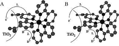 | ||
| Fig. 22 Ball-and-stick models for Ru(bpy)2(dcb)/TiO2 depicting the two possible mechanisms for photo-induced electron injection into TiO2 and regeneration of the sensitizer: (A) MLCT excited-state electron injection followed by regeneration of the oxidized sensitizer by the solution donor, D; (B) Reduced sensitizer injection that results from reductive quenching of the excited state by D followed by dark electron injection from the reduced sensitizer. Taken from Scheme 1 of ref. 320. | ||
Kirsch-De Mesmaeker and co-workers first reported compelling evidence for reduced ruthenium sensitizers transferring electrons to SnO2electrodes.319 The coincidence of Stern–Volmer constants measured by analysis of the photocurrent enhancement and PL quenching with hydroquinone donors left little doubt as to the sensitization mechanism. Additional spectroscopic evidence for photo-induced electron injection by reduced sensitizers was reported for Ru(bpy)2(dcb)/TiO2 in 0.1 M TBAClO4 acetonitrile electrolyte containing neutral, organic phenothiazine (PTZ) electron donors.321 Nanosecond transient absorption data demonstrated the rapid formation of TiO2(e−)/PTZ+, while in the absence of PTZ there was little-to-no evidence for injection. Injection was rate limited by diffusional quenching of the MLCT excited state so the RuII(bpy)2(dcb−)/TiO2 intermediate was not directly observed.
An interesting case of photo-induced, reduced-sensitizer electron injection was reported with the bimetallic sensitizer (bpy)2 RuII–BL–RhIII(dcb)2/TiO2, BL = 1,2-bis[4-(4′-methyl-bpy)]ethane, Fig. 23(a).322 About two-thirds of the MLCT excited states of the ruthenium chromophore were quenched by electron transfer to the Rh(dcb)2group to form a (bpy)2RuIII–BL–RhII(dcb)2/TiO2 charge-separated state while the remaining directly injected an electron into TiO2.** This observed branching ratio was proposed to result from different surface orientations. Approximately 40% of the intramolecular, charge-separated state, (bpy)2RuIII–BL–RhII(dcb)2/TiO2, injected electrons into TiO2 to form (bpy)2RuIII–BL–RhIII(dcb)2/TiO2(e−), while the remaining underwent back-electron transfer to form ground-state products, Fig. 23(b). The RuII*-based injection occurred within the time resolution of the instrument, i.e. <10 ns, while the RhII-based injection occurred in <100 ns following light excitation.
![(A) A diagram of a [(bpy)2RuII–BL–RhIII(dcb)2]5+ sensitizer bound to a TiO2 nanocrystallite. (B) A schematic depicting the relative redox energies, lifetimes, and quantum yields for each step in the photo-induced injection process. Taken from Fig. 10 and 12, respectively, of ref. 322.](/image/article/2009/CS/b804321n/b804321n-f23.gif) | ||
| Fig. 23 (A) A diagram of a [(bpy)2RuII–BL–RhIII(dcb)2]5+ sensitizer bound to a TiO2 nanocrystallite. (B) A schematic depicting the relative redox energies, lifetimes, and quantum yields for each step in the photo-induced injection process. Taken from Fig. 10 and 12, respectively, of ref. 322. | ||
In order to realize efficient DSSCs that operate by this mechanism, sensitizers that are potent photo-oxidants must be utilized. This stems from that fact that the I3−/I−redox mediator is the only redox mediator that yields high light-to-electrical power conversion efficiencies and the I˙/I−reduction potential is rather positive. RuII sensitizers that are strong excited-state oxidants can be prepared with ligands such as 2,2′-bipyrazine (bpz). For example, the Eo(Ru2+*/+) of [Ru(bpz)2(deeb)]2+ was found to be greater than +1.0 V vs.SCE69,70,323 (+1.24 V vs.NHE229). While the excited state of this and related sensitizers were found to be efficiently quenched by iodide or phenothiazine donors, the reduced form of the compound that resulted, RuII(bpz)(bpz−)(deeb)/TiO2, did not inject electrons into TiO2.320 In fact, very similar transient absorption features were observed in solution, on TiO2, and on ZrO2, while extremely small photocurrents (IPCE < 10−4) were observed in DSSCs. Some improvement was observed when the semiconductor was changed to SnO2, but the injection yields remained poor.323
Another interesting case of reductive quenching of an excited state that did not result in electron injection was reported for the mono-anion of Z907/TiO2 in the presence of a high concentration of 1-propyl-3-methylimidazolium iodide.324 A new transient spectroscopic feature was discovered that was attributed to the reduced sensitizer, which presumably formed by reductive quenching of the excited state by iodide. The decay of this species was attributed to a back-reaction with I3− (t1/2 = ∼1 ms) yet it is not clear why this state did not inject electrons into TiO2.
4. Sensitizer regeneration
A Intramolecular regeneration
Considerable effort has been set forth to regenerate the oxidized sensitizer by intramolecular electron transfer. This could be considered a “hole” transfer reaction that translates the oxidizing equivalent away from the RuIII-metal center and, ideally, the TiO2 surface. Very similar mechanisms are well-known in the field of supramolecular photochemistry where compounds of the type (D)n–C–(A)m are often employed ((D)n are donor molecules, C is a chromophore/sensitizer, and (A)m are acceptor molecules). When solely two components are present the compounds are termed dyads.88,94,325,326 At TiO2 interfaces a variety of C*–D dyads have been characterized; to our knowledge, Wrighton and co-workers were the first to attach a dyad to a semiconductor electrode.327 The ability to control hole-transfer reactions at the molecular level is important for many classes of solar cells. One can envision future-generation DSSCs where multiple hole-transfer steps translate the oxidizing equivalent from the sensitized interface directly to a counter electrode thereby eliminating the need for the solution-based redox mediators that are required today, e.g. I3−/I−.In practice there are at least two ways in which D–C*/TiO2→ D+–C/TiO2(e−) reactions can occur. They correspond to charge-separation mechanisms from the excited or reduced states that were described in sections 3/B and 3/D, respectively. Since C* is a weaker oxidant than C+, it is possible to design dyads covalently bound to weak donors that only react by the first mechanism. When strong electron donors are used, the mechanistic pathway is dependent on the relative rate constants for excited-state electron injection and intramolecular charge separation. Since excited-state injection is often found to be ultrafast, the first mechanism probably predominates even though it cannot always be unambiguously identified.
It should be pointed out that in some regards N3/TiO2 is thought to undergo a similar intramolecular, charge-transfer process. DFT calculations for N3+ predict considerable hole density on the isothiocyanate ligands.56–58 It is also known from electrochemical measurements that there are two closely spaced oxidations for N3, the first is predominantly metal based while the second is mainly isothiocyanate based. Therefore, in the charge-separated state, N3+/TiO2(e−), there is likely some partial “hole transfer” from the RuIII-metal center to the isothiocyanate ligands. In most of the examples discussed below, the electronic coupling between the electron donor and the Ru-metal center is much weaker, giving rise to complete hole hopping rather than partial charge transfer.
When the dyad was anchored to TiO2 thin films and immersed in acetonitrile, MLCT excitation resulted in a new charge-separated state with an electron in TiO2 and an oxidized PTZ group, abbreviated PTZ+-RuII/TiO2(e−). It was not possible to determine the mechanism of charge separation yet the authors speculated that after excited-state electron injection, electron transfer from PTZ to the RuIII-metal center (−ΔG∼ 0.36 eV) produced PTZ+-RuII/TiO2(e−). Recombination of TiO2(e−)s with PTZ+ to yield ground-state products occurred with a rate constant of 3.6 × 10³ s−1. Excitation of a model compound that did not contain the PTZ donor under otherwise identical conditions gave rise to the immediate formation of a charge-separated state, RuIII/TiO2(e−), whose recombination kinetics were complex and analyzed by a distribution model with an average rate constant of 3.9 × 10⁶ s−1. Therefore, translating the “hole” from the RuIII-metal center to the pendant PTZ moiety slowed TiO2(e−) recombination by about three orders of magnitude. This work provided an example of how the principles of stepwise charge separation, originally developed in the field of supramolecular photochemistry, can be applied to solid-state materials.
Shortly thereafter, Grätzel and co-workers reported dyads that could undergo intramolecular “hole” transfer after excited-state electron injection.330 These authors emphasized the significant color changes that accompanied electron transfer and potential applications in photochromic devices. Interestingly, they observed long-lived charge-separation, like the PTZ+-RuII/TiO2(e−) described above, in some cases while not in others.
Since that time a number of dyads have been attached to TiO2 and are discussed further below. A commonly utilized electron donor is a triarylamine moiety, NAr3. Three RuII-NAr3-type sensitizers with tpy-based ligands were studied in order to determine the optimal spatial location of the amine donor in relation to the excited-state electron.330 One compound had a 4-(N,N-di-p-anisylamino)phenyl group conjugated to a second tpy ligand, the second contained a benzyl ether interlocking group between the same amine donor and the tpy ligand, and the third compound contained only a 4,4′,4″-trimethyl-tpy ligand, Fig. 24. The latter compound was also co-adsorbed with a donor moiety bound to a phosphonated ether. Using long-wavelength resonance Raman spectroscopy it was deduced that the excited electron in the excited state of the first compound was located on the donor-containing tpy ligand whereas for the other two compounds it was located on the surface-bound phosphonated-tpy ligand. For all three compounds, photo-induced electron injection occurred quantitatively in <1 ns in air. In propylene carbonate, the quantum yield for formation of NAr3+-RuII/TiO2(e−) was only 0.60 and occurred within 20 ns for the first compound while for the second compound it was unity with biphasic kinetics, a 10 ns component and a 100 ns component. The third compound with the co-bound donor experienced practically unity conversion to the NAr3+/TiO2(e−) charge-separated state. This study illustrated that remote injection was less efficient than injection from a surface-bound ligand.
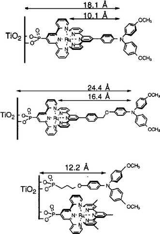 | ||
| Fig. 24 Chemical structures of sensitizers containing intramolecular, or nearby, organic donors so as to increase the charge-separation distance. Taken from Fig. 5 of ref. 330. | ||
Some remarkably long-lived charge-separated states were observed after pulsed-light excitation of similar compounds. By covalently attaching the ether-NAr3 donor group just described above to a dmb ligand in a cis-Ru(dmb-X)(dcb)(NCS)2/TiO2 system, the half-life of the charge-separated state was found to be over half a second, as shown schematically, Fig. 25(a).331 Haque, Durrant, and colleagues increased this lifetime further by employing Ru(4,4′-(R)2-bpy)(dcb)2/TiO2 systems, where R contained one triphenylamine group (NPh3), two NPh3 groups, or a poly(vinyl-NPh3) group of about 100 units, Fig. 25(b).332 The introduction of about 100 amines increased the half-life of the charge-separated state to over 4 seconds, as compared to 350 μs and 5 ms for the other two compounds, respectively. The kinetics for excited-state electron injection and subsequent hole transfer from the RuIII-metal center to the covalently bound NPh3 moiety occurred within the instrument response time, i.e.∼10 ns.
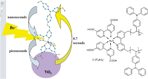 | ||
| Fig. 25 (A) A schematic depicting the cis-Ru(dmb-ether-NAr3)(dcb)(NCS)2 sensitizer bound to a TiO2 nanocrystallite and the overall mechanism for photoinduced charge separation and recombination with corresponding time scales. Taken from cover artwork of ref. 331. (B) The chemical structure of the sensitizer employed to increase the half-time of the S+/TiO2(e−) charge-separated state to over 4 s (n = 100). Taken from Scheme 1 of ref. 332. | ||
N3 derivatives, cis-Ru(4,4′-(R)2-bpy)(dcb)(NCS)2, R = NPh3 or CH3, bound to TiO2 thin films were examined in order to study the effects of RuIII-hole transfer to a triphenylamine moiety.82 Unexpectedly, both sensitizers exhibited similar transient features providing no evidence for hole transfer in the former sensitizer. Notwithstanding, the photoelectrochemical properties of the two sensitized thin-film electrodes differed significantly and a much larger Voc was measured for the NPh3-containing sensitizer. The authors speculated that the enhanced Voc resulted from a larger dipole that was nascently formed on the sensitizer bearing the NPh3 moiety. Based on the enhanced extinction coefficient of this dye and the results obtained when the small-perturbation Voc-decay technique was employed, it was proposed that photo-induced electron injection into the TiO2 acceptor states and partial hole delocalization from the RuIII-metal center to the NPh3 moiety occurred in one concerted step. Thus, increased charge separation could be achieved concomitant with electron injection by partial delocalization of the hole on the ligand.
A series of novel sensitizers each containing a 4′-X-tpy ligand (X = Ph–PO3(C2H5)2, Ph–PO3H2, PO3(C2H5)2, PO3H2, or COOH) bound to TiO2 were studied with hopes of increasing the charge-separation distance between the TiO2(e−) and oxidized sensitizer.333 Only the sensitizer shown in Fig. 26, containing a phenyl-amide-carotenoid bound to a second tpy, provided unequivocal evidence for intramolecular sensitizer regeneration and thus increased charge separation, which was complete in <10 ns. However, even though DFT calculations indicated that the LUMO and the MLCT excited state were located on the 4′-phenylphosphonate-tpy ligand which was bound to TiO2, injection yields were poor. It was postulated that the out-of-plane phenyl spacer gave poor electronic coupling to TiO2.
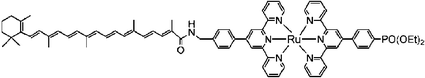 | ||
| Fig. 26 The chemical structure of the sensitizer employed to study intramolecular charge separation on TiO2 thin films. The hole was successfully transferred away from the RuIII-metal center and TiO2 surface to the carotenoid moiety. Taken from Scheme 3 of ref. 333. | ||
The compound [Ru(BTL)(deeb)2]2+, where BTL is 9′-[4,5-bis(cyanoethylthio)]-1,3-dithiol-2-ylidene]-4′,5′-diazafluorene, was found to have an extinction coefficient almost three times as large as Ru(bpy)32+ in the visible region.81 Interestingly, the transient absorption features in solution and on TiO2 differed greatly. In solution, a transient state was observed with spectroscopic properties characteristic of an MLCT excited state, with τ = 25 ns at −40 °C, whereas when bound to TiO2 a large positive absorption feature near 520 nm was observed and assigned to the oxidized dithiolene ligand. In fluid solution the driving force for reductive quenching of the MLCT excited state was unfavorable. However, when anchored to TiO2, an electron was injected and the hole had translated from the RuIII-metal center to the dithiolene-containing ligand, within 10 ns after light excitation, Fig. 27.
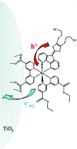 | ||
| Fig. 27 A schematic depicting a novel, high extinction coefficient sensitizer bound to a TiO2 nanocrystallite and photo-induced electron- and hole-transfer mechanisms. This sensitizer is unique in that the extended conjugation on the dithiolene-containing ligand is in the 3 and 3′ positions. Taken from cover artwork of ref. 81. | ||
Related studies with (bpy)2MII–bpt–RuII(dcb)2/TiO2 thin films (M = Ru or Os), abbreviated M–bpt–Ru, where bpt-H = 3,5-bis(pyridin-2-yl)-1,2,4-triazole, showed evidence for two different electron-injection mechanisms depending on M.335 For the all ruthenium compound, excited-state energy transfer to the TiO2-bound, dcb-containing, ruthenium moiety followed by excited-state injection was deduced based on transient PL and absorbance measurements. Although not directly observed, hole transfer to the proximal ruthenium moiety was thermodynamically favorable after excited-state injection. For the M = Os compound, excitation into the RuII-based MLCT band resulted in excited-state energy transfer to the proximal osmium moiety prior to injection, and after remote injection the hole was proposed to remain on the Os-metal center. The expected OsIII–bpt–RuII/TiO2(e−) product formed within the laser pulse (∼10 ns). It was proposed that since some of the exciting light was absorbed by the OsII moiety, and energy transfer to the ruthenium moiety was energetically unfavorable, some remote injection from the Os-localized excited state also occurred in this case.
Studies with a solution and surface-bound trinuclear ruthenium complex, (RuIII–RuII)(L)–amide–(bpy)RuII(dcb)2/TiO2, revealed that MLCT excitation of the mononuclear RuII-metal center resulted in a transient absorption spectrum indicative of (RuIII–RuII)(L)–amide–(bpy)RuIII(dcb)2/TiO2(e−), Fig. 28.336 This intramolecular charge-separated compound was completely formed by 200 ps, at which time the injection yield was deemed to be <10%. However, by 300 ns a spectrum consistent with (RuIII–RuIII)(L)–amide–(bpy)RuII(dcb)2/TiO2(e−) was observed and was shown to have a half-life, t1/2 = ∼1 ms. This illustrates that slow hole transfer can occur over large distances under the appropriate conditions.
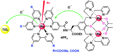 | ||
| Fig. 28 A schematic depicting a sensitizer employed to study intramolecular charge separation on TiO2 thin films. Interestingly, slow intramolecular charge separation between the mononuclear RuIII and dinuclear RuII–RuIII could be observed on the hundreds of nanoseconds time scale. Taken from cover artwork of ref. 336. | ||
Coordination compounds of the form [(LL)(L′L′)RuII(BL′)RuII(LL)(L′L′)]n+ (n = 2, 3 depending on the number of deprotonated carboxylic acid functional groups) were investigated on TiO2, where LL and L′L′ are bpy and/or dcb and BL′ is a bridging ligand: either tetrapyrido[3,2-a:2′,3′-c:3″,2″-h:2‴,3‴-j]phenazine (tpphz) or 1,4-bis(phen-[5,6-d]imidazol-2-yl)benzene (bfimbz), where phen is 1,10-phenanthroline.337 As the BL′ ligands are rigid and linear heteroaromatic entities, remote, excited-state electron injection could be examined with little fear of unexpected outer-sphere ligand–surface interactions due to ligand flexibility. It was shown that when BL′ was tpphz—a ligand possessing π* energetics below the π* levels of the surface-bound dcb ligand—injection could be time resolved due to the thexi state being localized on tpphz, away from a surface-bound dcb ligand and with less reducing power for injection. However, this slow injection was found to be not only distance- and/or driving force-dependent but orientation-dependent as well. When [(bpy)(dcb)RuII(tpphz)RuII(bpy)(dcb)]n+ (n = 2 or 3) was employed as the sensitizer injection could be time-resolved using nanosecond transient absorption spectroscopy, whereas with [ (bpy)2RuII(tpphz)RuII(bpy)(dcb)]n+ (n = 2 or 3) it could not, kinj >108 s−1. Using DFT geometry optimization software it was hypothesized that electronic coupling, and not distance from the TiO2 surface, could explain the differences, Fig. 29. The location of the π* orbital of the heterobinuclear complex in relation to the TiO2 surface allowed for better electronic coupling between the sensitizer and the TiO2 DOS even though the Nphenazine–Ti distance was increased by over a factor of two. Photoelectrochemical measurements supported this and indicated that by increasing the distance for back-electron transfer the photocurrent efficiency could be enhanced.
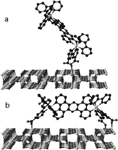 | ||
| Fig. 29 Density Functional Theory (DFT) optimized geometry for two bimetallic RuII compounds. When a distal ligand possessed carboxylic acid functional groups capable of binding to the TiO2 surface, the geometry of the minimized energy configuration had it binding to the surface as well (b). Although the LUMO of the doubly bound form was spatially closer to the TiO2 surface, the singly bound sensitizer had a faster injection rate due to better electronic coupling with the TiO2 DOS. Taken from Fig. 7 of ref. 337. | ||
B Intermolecular regeneration
In DSSCs, redox mediators are added to the external electrolyte. The reduced form of the mediator must regenerate the oxidized sensitizer by electron transfer prior to recombination with the injected electron. The oxidized form of the redox mediator is then reduced at the platinum counter electrode, a process not described herein. Ideally, all redox states of the redox mediator would not competitively absorb light. Although ion-pairing or surface adsorption with such mediators may occur, for the organization of this review we consider these to be intermolecular electron-transfer reactions.a Sensitizers in solution. By far the most effective donor in DSSCs is iodide.12 All confirmed reports of light-to-electrical power conversion efficiencies over 10% utilize iodide and state-of-the-art DSSCs require iodide.12 While many of the details of iodide oxidation at sensitized electrodes are now becoming available, it is important to point out that the aqueous redox chemistry of iodide and homogeneous reactions with transition-metal compounds have long been known.338–342
Shown in Scheme 1 is a Latimer-type diagram for the aqueous redox chemistry of iodide. Additional values and details are available in the review by Stanbury.338 The formal one-electron reduction potential of the iodine atom is very positive, Eo(I˙/I−) = +1.33 V vs.NHE.338 Therefore, a potent oxidant is required to generate iodine atoms. However, another pathway exists in which two iodides can be oxidized directly to I2˙−, Eo(I2˙−) = +1.03 V vs.NHE.338 Based on potentials alone, it is tempting to conclude that this latter pathway is the only mechanism available to oxidized sensitizers like N3+, since generation of iodine atoms would be thermodynamically unfavorable by close to 250 mV.25 However, it should be kept in mind that the potentials listed are for standard-state conditions in aqueous electrolytes and that adsorption to the TiO2 surface may have a significant effect. Walter and Elliott have provided evidence that interactions between iodide and the bpy ring may also activate iodide.343 Furthermore, the values given in Scheme 1 are for aqueous solutions. Since there is good reason to believe that the reduction potentials will vary significantly with solvent, it would be tremendously helpful to this field if a corresponding Latimer-type diagram in acetonitrile was available since there is good reason to believe that the reduction potentials will vary significantly with solvent. For example, the equilibrium constant for reaction (9) is reported to be >106 M−1 in CH3CN344–349 but is only 700–800 M−1 in water.350
| I− + I2⇌ I3− | (9) |
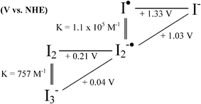 | ||
| Scheme 1 | ||
The transition-metal redox chemistry of iodide has previously been reviewed.341,342 Two mechanisms have been observed, based on reactions (10) and (11):
| Mox + I−→ Mred + I˙ | (10) |
| Mox + 2I−→ Mred + I2˙− | (11) |
Much less is known about MLCT excited-state oxidation of iodide. The alternative, reduced-sensitizer electron-injection process requires interactions of the excited state and iodide. Early studies with [RuIII(bpy)2(bpy−)]2+* revealed very inefficient electron transfer, i.e. 1 × 10⁶ M−1 s−1.354,355 Interestingly, excited-state quenching of [RuIII(bpy)2(dcb−)]2+* anchored to SiO2 appears to be somewhat more efficient, i.e. 1 × 10⁸ M−1 s−1.356
We recently found that excited-state electron-transfer reactions with iodide were significant when ion-paired with the ground-state sensitizer.133,357 Addition of iodide to a dichloromethane solution of [Ru(bpy)2(deeb)]2+ resulted in significant changes to the ground-state absorption spectrum. A decrease in PL and excited-state lifetime accompanied the absorption changes consistent with both static- and dynamic-quenching mechanisms, respectively. A Benesi–Hildebrand-type analysis of these absorption changes yielded equilibrium constants for ion-pairing that were within experimental error the same as those abstracted from PL quenching data, Keq = 59700 M−1. Similar behavior was observed in acetonitrile and/or with Ru(bpy)32+, however an iodide concentration that was two orders of magnitude larger was required. Transient absorption measurements clearly showed an electron-transfer mechanism with the appearance of I2˙− and no evidence for intermediate iodine atom formation; thus the mechanism appeared to follow reaction (11). The cage escape yields were low, ϕ = 0.25, but increased to 0.50 with Ru(bpy)32+. Remarkably, the solid-state crystal structure of Ru(bpy)2(deeb)I2 had both iodides associated with the carbonyl oxygens of the ester groups, Fig. 30. One might have anticipated that Coulombic repulsion would have resulted in a larger inter-ionic distance then the ∼6 Å observed. If a similar structure exists in solution the iodides would be well-positioned for a concerted reduction of [RuIII(bpy)2(deeb−)]2+* and formation of I2˙−. This is an intriguing possibility as excited-state reactions that form chemical bonds are rare in all of photochemistry. Although, evidence for intermediate I˙ formation by reaction (10) has recently been observed in our labs.358
![Space-filling representation of the crystal structure of a single sensitizer determined by X-ray diffraction showing two iodides associated with the deeb ligand in [Ru(bpy)2(deeb)]2+. This geometry would allow for facile reductive quenching of the excited or oxidized forms of the molecule and the proximity of a second iodide could favor I2˙− generation as per eqn (11). Taken from cover artwork of ref. 133.](/image/article/2009/CS/b804321n/b804321n-f30.gif) | ||
| Fig. 30 Space-filling representation of the crystal structure of a single sensitizer determined by X-ray diffraction showing two iodides associated with the deeb ligand in [Ru(bpy)2(deeb)]2+. This geometry would allow for facile reductive quenching of the excited or oxidized forms of the molecule and the proximity of a second iodide could favor I2˙− generation as per eqn (11). Taken from cover artwork of ref. 133. | ||
b Sensitizer/TiO2 systems. The first heterogeneous reduction of RuIII-polypyridyl compounds by iodide was reported by Fitzmaurice and Frei.359 Photo-induced electron injection into colloidal TiO2 from [RuIII(dcb)2(dcb−)]2+* was followed by oxidation of iodide in acidic aqueous solution. From the pseudo-first-order transient kinetics in 0.5 to 100 mM KI, a second-order rate constant for iodide oxidation of ∼2.5 × 10⁹ M−1 s−1 was abstracted. The data were ascribed to be most consistent with formation of ion-pairs.
Since that time there have been a number of studies aimed at abstracting the rate at which the RuII form of the sensitizer is regenerated. These experiments were usually performed by monitoring the recovery of the MLCT absorption bleach after pulsed-laser excitation at wavelengths where the iodide oxidation products did not appreciably absorb light. While this has proven to be a reasonable way of quantifying rate constants for regeneration of the RuII state, little information regarding the mechanism(s) of iodide oxidation is obtained. For this reason, we briefly summarize the key observations.
Most studies of this type were performed with N3/TiO2. At low iodide concentrations, the regeneration rate was found to be first order in iodide. At higher iodide concentrations, a static component was often observed. Under the 0.5 M iodide concentration of a DSSC, regeneration is often stated to be complete within 10 ns.11,13 The rate constant for regeneration of the oxidized dye, RuIII(bpy)2(dcb)/SnO2, by iodide was determined to be 1.2 × 10¹⁰ M−1 s−1.356 Durrant and co-workers have recently provided evidence that the regeneration rate is dependent on the Eo(RuIII/II) of the sensitizer.360 With Ru(dcb)2(CN)2/TiO2 thin films an intermediate was observed and assigned to a [RuIII, I−] ion-pair. Reaction of this with a second iodide was proposed to yield I2˙−.
The rate of reactivity of iodide with N719+/TiO2(e−) increased in the presence of Li+ and other cations with large charge-to-radius ratios.361 It was also noted that the half-time for sensitizer regeneration abruptly shortened when the concentration of Li+ was increased to between 10 and 50 mM, Fig. 31(a). Using electrophoretic measurements, the point of zero ζ-potential (PZZP) was determined to occur at 3 mM Li+, a concentration slightly less than that required for the abrupt change in half-time, Fig. 31(b). Also, by titration of iodide to positively charged TiO2 particles in the presence of Mg2+, experimental data suggested that iodide adsorbed within the Helmholtz layer of the particles even in the presence of bulky dyes. It was concluded that the abrupt change to faster sensitizer regeneration occurred due to ion-pairing of iodide anions with the TiO2 surface or sensitizer resulting in an increased occurrence of the faster termolecular reaction (11).
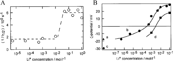 | ||
| Fig. 31 (A) Plot of the inverse half-lives for the regeneration of N719+/TiO2(e−) by iodideversus the logarithm of the concentration of Li+. (B) A similar plot depicting the point of zero ζ-potential (PZZP) for TiO2nanoparticles as a function of the logarithm of the Li+ concentration for (b) unsensitized TiO2 and (d) N719/TiO2. Both plots for N719/TiO2 noticeably change behavior near 2 × 10⁻²–2 × 10⁻³ M. Taken from Fig. 4a and 3, respectively, of ref. 361. | ||
a Organic donors. With a few notable exceptions there has been very little progress in using one-electron transfer, outer-sphere redox couples as mediators. The published literature does not accurately reflect the experimental efforts that have been put forth in this area. This stems from the fact that it is neither rewarding nor easy to publish data on solar light-to-electrical power conversion efficiencies of <0.1%. Some time ago we showed that phenothiazine donors were able to efficiently regenerate the oxidized sensitizer.329 However, one needed a pico-ammeter to measure any photocurrent due to quantitative recombination of TiO2(e−)s with PTZ+. In other words, PTZ+ molecules were unable to escape the mesoporous film before recombination. This result appears to be very general. Gregg and co-workers found similar behavior with FeCp2 donors.363 By coating the sensitized electrode with silanes, a large increase in the photoelectrochemical response was observed that was reasonably attributed to attenuation of the recombination reaction of TiO2(e−)s with FeCp2+, Fig. 32.
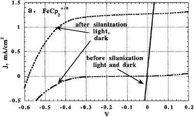 | ||
| Fig. 32 Current–voltage curves under simulated solar irradiance conditions and in the dark showing that silanization of a Ru(bpy)2(dcb)/TiO2 thin film electrode dramatically improved the current–voltage characteristic of regenerative solar cells employing FeCp2+/0 as the redox couple. This data is consistent with the silanes attenuating TiO2(e−) + FeCp2+ recombination. Taken from Fig. 7a of ref. 363. | ||
In early aqueous DSSC studies, Grätzel showed that hydroquinone was a satisfactory donor.364 A polycrystalline TiO2 (anatase) electrode sensitized with Ru(dcb)32+ in 10 mM aqueous NaCl (pH 2.6 with HCl) solution with 1 mM hydroquinone gave maximum IPCE values of 44%. Three years later, a DSSC containing 1 mM aqueous HClO4 and either 10 mM hydroquinone/100 mM LiClO4 or 1 M KI electrolyte resulted in similar maximum IPCE values, Fig. 33.365 A comparison of halide redox mediators in acidic aqueous electrolyte, i.e. 1 mM HClO4, illustrated that Ru(dcb)3/TiO2 thin-film electrodes in electrolyte solution containing 1 M LiClO4/1 mM Br2 resulted in a monochromatic light-to-electrical power conversion efficiency of 12%.365 However, the redox mediator was outperformed by the I3−/I−redox mediator under short-circuit conditions. The more negative photocurrent onset observed for iodide, relative to hydroquinone and bromide, suggested a surface adsorption-induced shift in the flatband potential in the iodide-containing electrolyte.
 | ||
| Fig. 33 Current–voltage curves for Ru(dcb)3/TiO2 in aqueous electrolyte illustrating that bromide and dihydroquinone function nearly as well as iodide in DSSCs under short-circuit conditions. Taken from Fig. 3 of ref. 365. | ||
A comparative study of the pseudohalide redox mediators (SeCN)2/SeCN− and (SCN)2/SCN− with the standard I3−/I−redox mediator in N3/TiO2 regenerative DSSCs was reported.366 As the reduction potentials of the pseudohalides were 190 and 430 mV more positive than I3−/I−, respectively, it was postulated that an increased Voc would result. Interestingly, the Voc for the DSSC containing the (SeCN)2/KSeCN redox mediator was about the same as for the I3−/I−redox mediator while that for (SCN)2/NaSCN was considerably smaller. The iscs differed by a factor of four under monochromatic (500 nm) light excitation. The injection yields were independent of the redox mediator in 250 mM LiClO4 acetonitrile electrolyte containing 100 mM of the sodium or potassium salt of the reduced redox mediator, but the rate of regeneration followed the order I− > SeCN− > SCN−. While SCN− and SeCN−oxidation by N3+/TiO2 was thermodynamically favored, the oxidation kinetics were sluggish which allowed a larger fraction of the injected electrons to recombine with N3+.
Interestingly, Wang and Grätzel observed more promising behavior for Z907/TiO2 thin films with the (SeCN)2/SeCN−pseudohalide redox mediator in the 1-ethyl-3-methylimidazolium (EMI) selenocyanate ionic liquid with added K(SeCN)3.367 Although this ionic liquid was found to be 35 times less viscous than the traditional 1-propyl-3-methylimidazolium (PMI) iodide ionic liquid, it was over 28 times more conductive at room temperature and could solubilize approximately eight times more (SeCN)2/SeCN− than PMI could with I3−/I−. By transient absorption spectroscopy, it was shown that Z907+/TiO2(e−) could be regenerated fastest in EMI-SeCN− as compared to PMI-I− and the analogous EMI-SCN− ionic liquid. This was contrary to the findings of Oskam et al. in acetonitrile electrolytes.366 It was also shown that the maximum IPCE was close to unity and the overall light-to-electrical power conversion efficiency under 1 sun, AM1.5-simulated irradiation was 7.5%.
Recent studies have investigated 2,2,6,6-tetramethyl-1-piperidinyloxy radical (TEMPO) as a possible redox mediator.368,369Nitrosyl tetrafluoroborate (NOBF4) was added to TEMPO in order to generate a TEMPO+/TEMPO redox couple in a 1 : 9 stoichiometry, similar to the ratio of I3−/I− employed in champion DSSCs. When 1 M TEMPO was compared to the same concentration of iodide both the isc and Voc were slightly increased. The light-to-electrical power conversion efficiency for an organic sensitizer bound to TiO2 under 1 sun, AM1.5-simulated irradiation was 5.4%. When the TEMPO concentration was decreased to 0.1 M, the Voc actually increased to ∼910 mV.
b Transition-metal donors. Octahedral CoII diimine compounds have proven to be effective donors for sensitizer regeneration and CoIII/IIredox mediators have led to promising light-to-electrical power conversion efficiencies in DSSCs. The CoIII/II self-exchange rate constants are known to be particularly sluggish, behavior that is reasonably understood by the d6/d7 electronic configurations that give rise to large inner-sphere reorganization energies.370 It is possible that these same electronic factors are responsible for the slow rate constants for TiO2(e−) + CoIII recombination reactions and the reasonable photocurrent efficiencies that have been reported when CoIII/IIredox couples have been used.
The first studies of cobalt mediators were by Grätzel and co-workers.371 A DSSC based on the [CoIII/II(dbbip)2]3+/2+redox couple, where dbbip is 2,6-bis(1′-butylbenzimidazol-2′-yl)pyridine), resulted in photovoltaic performance that rivalled the traditional I3−/I−redox mediator when a ∼150 nm thick spray-pyrolyzed titania underlayer was deposited on the electrode substrate. It was shown that the exchange current density for the CoIII/II couple at fluorine-doped tin oxide (FTO) was 7 × 10⁻⁶ A cm−2 in an acetonitrile–ethylene carbonate (40 : 60, v/v) electrolyte.362 As this value was at least two orders-of-magnitude lower than that measured at platinum but more than two orders of magnitude higher than that of the I3−/I−redox couple measured at FTO in the same electrolyte, a titania blocking layer was employed to slow this undesirable reaction. Using the cis-Ru(4-methyl-4′-hexadecyl-bpy)(dcb)(NCS)2 sensitizer and a 1 : 9 stoichiometric ratio of CoIII : CoII in the same electrolyte mixture, a maximum IPCE of >65% was realized and, under 0.094 suns, AM1.5-simulated irradiation, a light-to-electrical power conversion efficiency of 5.2% was measured.371 The use of a neutral sensitizer was found to be necessary in order to attenuate the adsorption of cationic redox species onto TiO2. When CoII(dbbip)22+ was added above a threshold of 10 mM, the second-order rate constant for regeneration—first order in N3+/TiO2 and first order in CoII(dbbip)22+—was 2.9 × 10⁶ M−1 s−1, approximately an order-of-magnitude smaller than values reported for NaI. However, at 100 mM the pseudo-first-order rate constants were similar to those found with the same concentration of TBAI.361 The change in apparent second-order rate constant was thought to be due to surface adsorption of the cationic redox couple at low concentrations. Adding to previous work, it was shown that the isc for a DSSC employing Z907/TiO2 was dependent on the counterion of the solution CoIII/IIredox mediator; the perchlorate salt worked the best.372 As expected, for the perchlorate-based redox mediators whose Eo(CoIII/II) varied over 190 mV, a similar 180 mV variation in Voc was realized. The largest Voc recorded was 660 mV accompanied by a 7.9% light-to-electrical power conversion efficiency under 0.1 suns, AM1.5-simulated irradiation.
Upon introduction of LiClO4 to DSSCs the lifetime of the TiO2(e−)s373,374 increased for cobalt-based redox couples whereas for the I3−/I−redox mediator it decreased. This was rationalized as being due to a decrease in the local concentration of the cationic or neutral cobalt-based redox couples near the TiO2 surface when cationic Li+ was present.373,374
A family of cobalt redox couples employing derivatives of bpy, phen, and tpy ligands were studied by Bignozzi, Elliott, and colleagues.375 The best cobalt-based mediator, based on [CoIII/II(DTB)3]3+/2+ perchlorate (DTB = 4,4′-di-tert-butyl-bpy), resulted in DSSCs exhibiting light-to-electrical power conversion efficiencies within 80% of that of a comparable I3−/I−-mediated DSSC under 1 sun, AM1.5-simulated conditions. Also, in contrast to the I3−/I−redox mediator, addition of Li+ to the cells increased not only the isc but the Voc as well! This was proposed to be due to a decrease in the rate of recombination of TiO2(e−)s and CoIII most likely from an increase in overpotential for reduction of the CoIII species at the back FTO contact. In addition, cyclic voltammograms with platinum electrodes revealed sluggish interfacial, CoIII/II electron-transfer kinetics relative to carbon and gold. Although gold was optimal, FTO electrodes coated with graphite nanoparticles initially outperformed platinum in DSSCs; however, the carbon-coated FTO electrodes degraded with time. Nevertheless, the initial response was encouraging and shows promise for replacing platinum with a less-expensive, carbon-based material for use as a counter electrode.
Although large reorganization energies and slow-electron transfer kinetics for cobalt-based redox couples are advantageous as they attenuate the unwanted, recombination reaction, TiO2(e−) + CoIII→ TiO2 + CoII, these characteristics are undesirable with respect to sensitizer regeneration, S+/TiO2(e−) + CoII→ S/TiO2(e−) + CoIII. Rapid sensitizer regeneration and sluggish recombination kinetics are traits that make the I3−/I−redox mediator optimal. By using co-mediators in conjunction with [CoIII/II(DTB)3]3+/2+ it was proposed that these traits could be realized in non-iodide-based systems.124 Both PTZ and FeCp2 were employed in Z907/TiO2 DSSCs, due to their small reorganization energies, rapid electron transfer kinetics, and reduction potentials intermediate between that of [CoIII/II(DTB)3]3+/2+ and Z907+/0. By transient absorption spectroscopy the bleach due to Z907+/TiO2(e−) was found to recover in the presence of 0.1 M donor in the order FeCp2 > PTZ > Co(DTB)32+ > no donor, whereas by chronocoulometry at FTO, PTZ/CoII 1:2 molar mixtures were found to turnover 45% faster than FeCp2/CoII mixtures. Thus, the maximum IPCE, i.e. >80%, was achieved for 0.075/0.15 M PTZ/CoII (1:2 molar ratio) in acetonitrile after generating steady currents by photolysis for 10–15 min in order to generate some CoIII. The Voc and FF, 650 mV and 0.63, respectively, under 0.1 suns, AM1.5-simulated conditions, were both larger than for an equivalent DSSC employing the LiI/I2redox system (0.3/0.03 M). However, the light-to-electrical power conversion efficiency was less due to mass-transport limitations of the bulky cobalt redox mediator. By binding Os(dcb)2Cl2 to FTO the exchange current for [CoIII(DTB)3]3+ reduction was greatly enhanced.376 When employed in an N3/TiO2 DSSC, the isc and Voc were only slightly attenuated as compared to a gold counter electrode and, using a three electrode measurement, the potential of the Os(dcb)2Cl2/FTO counter electrode was only slightly perturbed near open-circuit conditions.
CoIII/II redox couples based on triazine ligands have been synthesized and characterized.377 The heteroleptic Co(triazine-R)Cl2 compounds were shown to have Eo(CoIII/II) = ∼+0.75 V vs.SCE (+0.99 V vs.NHE229), considerably more positive than previously reported Co-based redox mediators. However, this redox couple has yet to be employed in a functioning DSSC. It will be interesting to see if regeneration by this redox mediator can compete kinetically with charge recombination.
CuI has a d10 electronic configuration and compounds like Cu(bpy)2+ often adopt a tetrahedral geometry in solution and in the solid state. The CuII form is subject to a Jahn–Teller distortion that often manifests itself in a geometry with more co-planar diimine ligands, i.e. a flattening, and a fifth ligand from solvent or a counterion axially ligated. It is possible to photoinduce these structural changes and they have been characterized by time-resolved X-ray techniques.378 Like the CoIII/IIredox mediators, CuII/I couples have large reorganization energies, slow self-exchange rate constants and show some modest success as mediators in DSSCs. For example, CuI-pyridyl and CuI-pyridyl-quinoline compounds have been studied in DSSCs.379 The best-performing mediators produced a maximum IPCE of ∼40% and yielded higher Vocs and FFs than the I3−/I−redox couple under the same experimental conditions. This was attributed to a decreased dark current due to the large reorganization energy of the CuII/Iredox couple.
Unfortunately the large reorganization energies for CuII/Iredox mediators suffer the same pitfalls as their CoIII/II counterparts, i.e. slow sensitizer regeneration. Thus, a CuI compound with a distorted tetrahedral geometry was employed in order to help reduce the large reorganization energy.380 When [CuII/I(dmp)2]2+/+ was employed as the redox mediator, where dmp is 2,9-dimethyl-phen, a light-to-electrical power conversion efficiency of 2.2% under 0.2 suns, AM1.5-simulated irradiation was obtained with N719/TiO2-based DSSCs. The methyl groups were proposed to prevent planarization of the dmp ligands which manifests itself in a positive shift in Eo(CuII/I). Significantly, a higher Voc was realized with the copper mediator as compared with I3−/I− under the same experimental conditions.
Recent results from our laboratories suggest new directions for fundamental research and raise the question of what the term ‘regeneration’ actually means. These new results are best understood with an example, [Ru(dtb)2(dcb)]2+, where dtb is 4,4′-di-tert-butyl-bpy. Fig. 34(a) shows the absorption and PL spectra of a Ru(dtb)2(dcb)/TiO2 thin film immersed in 0.1 M LiClO4 acetonitrile and in neat acetonitrile. In the presence of Li+ both maxima red-shifted and their intensity decreased relative to neat acetonitrile. The significant quenching of the PL results from enhanced excited-state electron injection into TiO2 as described previously herein.254
 | ||
| Fig. 34 (A) Absorption and photoluminescence spectra of Ru(dtb)2(dcb)/TiO2 in 0.1 M LiClO4 acetonitrile electrolyte (red spectra) and in neat acetonitrile after removal of the LiClO4 by ten neat acetonitrile washings (black spectra). (B) Transient absorption difference spectra for three Ru(dtb)2(dcb)/TiO2 thin films at the indicated surface coverages and delay times measured after pulsed 532 nm excitation in 0.1/0.5 M LiClO4/TBAI acetonitrile electrolyte. Overlaid are simulations of the data represented by dashed lines. Inset: Time-resolved, single wavelength absorption difference spectra measured at 510 nm for each surface coverage, corresponding to cation transfer, and a single difference spectrum measured at 433 nm (black spectrum with orange fit), corresponding to I3− loss due to TiO2(e−) + I3− recombination. Taken from Fig. 1 and 2, respectively, of ref. 381. | ||
Pulsed 532 nm excitation of Ru(dtb)2(dcb)/TiO2 in 0.1/0.5 M LiClO4/TBAI acetonitrile electrolyte resulted in the microsecond absorption difference spectrum, Fig. 34(b). Under such conditions, one would expect to observe a TiO2(e−) and oxidized iodide products, e.g. I3−. Regardless of the mechanism for iodide oxidation, most of the I2˙− should have disproportionated by this sufficiently long time delay. The absorption features characteristic of I3− (λ < 420 nm) and TiO2(e−)s (λ > 560 nm) were indeed observed. However, the absorption band centered at 460 nm and the bleach at 510 nm could not be assigned to any conceivable electron-transfer products.
Spectral modeling indicated that the absorption features at 460 and 510 nm resulted from [Ru(dtb)2(dcb)]2+ sensitizers that were regenerated in a Li+-deficient milieu. In other words, the sensitizers that were initially photo-excited had an absorption spectrum shown in red while immediately after regeneration their spectrum was that shown in black, Fig. 34(a). Overlaid on the data in Fig. 34(b) are simulations based on the weighted addition of (1) the absorption spectrum of I3−, (2) the TiO2(e−) absorption spectrum, and (3) the difference in the absorption spectra of Ru(dtb)2(dcb)/TiO2 in the absence minus the presence of Li+. Similar sensitizer absorption features were observed when PTZ was used in place of iodide. The excellent agreement between observed and simulated spectra provided compelling evidence that these sensitizers were regenerated in an environment that lacked outer-sphere Li+ interaction(s). This behavior was also observed after pulsed-light excitation of Ru(bpy)2(dcb)/TiO2 and Ru(bpy)2(dcbq)/TiO2 in 0.5 M iodide electrolyte as well as previously in the published literature for N3/TiO2382 and Ru(bpy)2(dcb)/SnO2.356 In all cases, absorption features were observed that were not due to oxidized iodide products, TiO2(e−)s, or other redox states of the sensitizers. They were, however, reasonably described as sensitizers regenerated in an environment depleted of Li+.
The absorption changes that correspond to cation transfer were well described by the Kohlrausch–Williams–Watts (KWW) function for a distribution of rate constants (distributions are shown in Fig. 35(a)):
 | (12) |
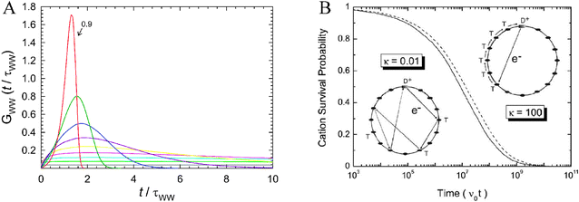 | ||
| Fig. 35 (A) Normalized Levy distributions of lifetimes calculated using the indicated values of β from the KWW model. As β approaches 1, the distribution approaches a Dirac δ function in shape and thus the kinetics would begin to follow a simple first-order model. Taken from Fig. 2 of ref. 402. (B) Simulated time-resolved spectra based on the random-flight multiple-trapping model of Tachiya and colleagues on the left and the multiple-trapping, nearest-neighbor CTRW model of Nelson et al. on the right. Although similar in shape, the trapping–detrapping rate is four orders-of-magnitude slower in the former. Taken from Fig. 18 of ref. 401. | ||
The spectral data indicated that Li+ transfer away from the sensitizer occurred in <10 ns. Furube et al. reported time-resolved infrared data consistent with picosecond Li+ transfer after excited-state injection by coumarin sensitizers, behavior attributed to Coulombic repulsion between the oxidized coumarin and Li+.387 As cations are required for charge compensation of the injected electron, that could also induce Li+ to migrate away from the oxidized sensitizer. As mentioned previously, intercalation of Li+ is known to accompany reduction of anatase TiO2. In this regard, we found that the same sensitizer spectral changes could be observed by partial electrochemical reduction of the TiO2, i.e. when no oxidized sensitizer was present, indicating that charge compensation plays a role.
After fast excited-state electron injection into TiO2 and regeneration by iodide, sensitizers were present in an environment distinctly different from that prior to light absorption. Significantly, the newly generated sensitizers were in an environment that is known to be less favorable for excited-state electron injection.254 Under 1 sun, AM1.5 irradiation, the slow (μs—ms) cation transfer is not expected to limit the efficiency of DSSCs as a typical RuII sensitizer absorbs light approximately twice every second.388 However, at higher irradiances or at planar TiO2 surfaces this effect may limit light-to-electrical power conversion efficiencies. In all cases, the sensitization rate constants shown in Fig. 1 need to be modified. The oxidized RuIII sensitizer may be reduced to RuII on a nanosecond time scale, however it is not brought back to the environment prior to light absorption until slow (μs—ms) cation transfer has taken place.
5. Charge recombination
Charge-recombination processes at sensitized semiconductor interfaces have been studied in considerable detail. Reactions of TiO2(e−)s with: (A) the oxidized sensitizer; and (B) acceptors in the electrolyte, Step IV in Fig. 1, have received much attention. As described in section 4/B/i/b, regeneration of the oxidized sensitizer by iodide is rapid and quantitative in champion DSSCs. Therefore, reaction IV–A is generally not relevant to these cells. It is, however, important in DSSCs employing alternative redox mediators or sensitizers whose ground-state reduction potentials are less favorable for regeneration than that of N3, Eo(RuIII/II) < +0.85 V vs.SCE25 (+1.09 V vs.NHE229). It may also become relevant at high irradiances or in viscous electrolytes. The transparent nature of the mesoporous, nanocrystalline TiO2 (anatase) thin films allows this process to be quantified in a transmission mode with signal-to-noise ratios comparable to what can be achieved in fluid solution. Mechanistic insights have been gained from transient absorption measurements made under open-circuit conditions in the absence of an external electron donor such that each injected electron recombines with oxidized sensitizers.In champion DSSCs, charge recombination to acceptors within the I3−/I− electrolyte is a very inefficient process. The fraction of TiO2(e−)s that recombine by this pathway is usually so small (<0.01) that it does not significantly influence the isc. However, TiO2(e−)s that recombine by this pathway are thought to have a significant influence on the quasi-Fermi level of the semiconductor and hence a large effect on the Voc. Intensity-modulated photovoltage/photocurrent spectroscopy (IMVS/IMPS) and time-domain transient photovoltage/photocurrent decays with appropriate modeling, have provided some insights into the mechanisms of this unwanted reaction.
A Electron-transport-limited charge recombination
In the late 1990s, our group at Johns Hopkins University and the groups at Imperial College in London provided evidence that charge recombination was not slow because of inherently small rate constants but because efficient separation of the injected electron and the oxidized sensitizer resulted in non-geminate recombination. Our own kinetic data showed that charge recombination was modeled by an equal-concentration, second-order process much like the analogous process in fluid solution.254,389 The concentration of charge-separated states was controlled by modulating the excitation irradiance or the Li+ concentration. When the concentration of charge-separated states, i.e.RuIII/TiO2(e−), was varied by over a factor of ten, the same second-order rate constant was abstracted from the data. A single second-order rate constant could be used to fit the first few microseconds of recombination, whereas a sum of two rate constants, i.e. a bi-second order kinetic model, was required to fit the entire transient. The possibility that a distribution of second-order rate constants had underlain the observed kinetic behavior could not be ruled out. The observed second-order rate constant, which was obtained directly from the transient absorption data, had the unconventional units of s−1. Accurate conversion to the more common units of M−1 s−1 was complicated by the heterogeneity of the sample which resulted in an ill-defined homogeneous optical path length. Assuming adherence to Beer’s Law and an optical path length equivalent to the film thickness, the back-electron transfer rate constants for RuIII(bpy)2(dcb)/TiO2(e−) → RuII(bpy)2(dcb)/TiO2 were found to be ∼9 × 10¹¹ and 3 × 10¹⁰ M−1 s−1 in 1.0 M LiClO4 acetonitrile electrolyte. Other researchers have employed the same methodology to abstract a weighted-average of the equal-concentration, second-order rate constants in units of M−1 s−1.390 The key advance was that efficient separation of the TiO2(e−) from S+ occurred thereby giving rise to somewhat-isolated TiO2(e−)s and oxidized sensitizers. Recombination was second order in nature not first order as had been previously assumed in the kinetic modeling. In fact, actinometry measurements showed no evidence for first-order, geminate recombination; every injected electron recombined by the second-order mechanism.Shortly thereafter, Nelson and the group from Imperial College proposed a model for charge recombination that involved transport of the injected electron to the oxidized sensitizer.183,185 The central idea was that charge carriers become trapped in localized states and that the kinetics for charge transport are dominated by the time constants for release from those states. Transient phenomena of this kind are termed ‘dispersive’391–393 when they are rate-limited by this step. A numerical model initially derived by Scher and Montroll based on a ‘continuous-time’ random walk (CTRW) where species move by diffusion on a lattice was utilized.394,395 The dispersive nature of such kinetics was introduced by applying a power-law, waiting-time distribution time step, ψ∝t−1−β, 0 < β < 1. For ‘normal’ diffusion the time step would be drawn from a Poisson distribution, ψ∝et/τ. The result of such a model are kinetics that follow the KWW function, which represents a distribution of rate constants as shown in Fig. 35(a),383–385 with β being equal to the inverse of the DOS non-ideality factor.185 Also, with this model, the t1/2 for the recombination ought to vary with the number of TiO2(e−)s per particle, n, as
| τ1/2 = Cn−1/β | (13) |
 | (14) |
Two models for trap-limited diffusion in disorder media were proposed by Nelson et al.185 The first was based on multiple-trapping-limited recombination as derived from the CTRW model where steps to all nearest neighbors were equally likely. The other was based on tunneling-limited recombination, where quantum-mechanical tunneling can result in long-range interactions, i.e. farther than nearest-neighbor. Fits to experimental charge-recombination data under external bias and plots of the half-lives versus the concentration of TiO2(e−)s strongly ruled out the latter model and supported the former given an exponential DOS.
Later, an extension to the multiple-trapping, nearest-neighbor CTRW model proposed by Nelson et al. was reported by Tachiya and colleagues.400,401 This new random-flight multiple-trapping model included the possibility of many neighbor interactions, where the probability that the detrapped electron will be captured by any empty, surface trap state within the nanoparticle is equal. Although similar in shape to the model proposed by Nelson et al., the calculated trapping–detrapping rate as a function of time was many orders-of-magnitude slower, Fig. 35(b).
A hopping model that differs from the multiple-trapping model has also been proposed by Bisquert.403 Instead of activated detrapping to the conduction band, electron transport occurs by direct transfer via localized states located at energies just below Ecb. However, a very high carrier density is needed to validate the model as all of the above models predict similar behavior at lower carrier densities.
There is now a wide body of charge-recombination data that is well modeled by the multiple-trapping, nearest-neighbor CTRW model and the KWW function. It allows a great deal of experimental data to be modeled with only two independent variables. However, the derived parameters (τo and β) do not always provide insights into the underlying dynamics. The KWW function has been “derived” by at least three different groups: (1) the already discussed CTRW model of Scher and Montroll;394,395 (2) a distribution of serially linked first-order rate constants by Anderson;404 and (3) fractal time concepts by Shlesinger.405 Although not as rigorous, Plonka has also shown that dispersive, second-order kinetics can lead to behavior that is well modeled by the KWW function.406 Anderson’s model is based on a distribution of first-order rate constants whose magnitudes decrease with time. Such behavior can be very difficult to distinguish from a second-order process where the rate decreases with time but the rate constant does not. We have in fact shown that it is often impossible to conclude whether a distribution or a sum of two discrete rate constants underlie complex kinetic behavior based simply on the quality of the fit.407 The point here is that while modeling charge recombination based on Scher and Montroll’s CTRW model makes good physical sense, it is not a unique fit and other models may ultimately provide more insights.
 | ||
| Fig. 36 (A) A diagram illustrating the space-charge potential drop across a TiO2 nanocrystallite that is ∼20 nm in diameter before and after contact with a solution electrolyte. (B) Color-coded topographical model illustrating the relative potential distribution for an ordered mesoporous network of such nanocrystallites. Taken from Fig. 5 and 6, respectively, of ref. 18. | ||
It is for this reason that TiO2(e−) diffusion is governed by the concerted motion of the electronic and electrolyte charges per the formula:17,410,421
 | (15) |
This ambipolar diffusion model was described in the early 1950s and solved computationally using a non-linear model in the late 1960s.422,423 Searson and co-workers first reported that the TiO2(e−) diffusion coefficient, in thin-film electrodes, was dependent on the light intensity and thus also on the concentration of TiO2(e−)s.424 Hagfeldt and colleagues later reported that TiO2(e−) diffusion in unsensitized mesoporous, nanocrystalline TiO2 (anatase) thin-film electrodes followed a cation-dependent mechanism.425 They termed the solution electrolyte an image cloud care of classical physics terminology.426Reduction of the electrolyte concentration from 500 to 20 mM resulted in a five-fold decline in the diffusion coefficient, indicative of an ambipolar diffusion mechanism. With laser pulses at 2 Hz in 500 mM LiClO4 acetonitrile electrolyte, the diffusion coefficients were shown to significantly slow, possibly due to insufficient time for Li+ deintercalation from within the anatase lattice. These same researchers later showed similar behavior for sensitized N3/TiO2 thin-film electrodes.427 Although not fit to an ambipolar diffusion model it was apparent that the cation concentration limited the TiO2(e−) collection time.
Frank and colleagues were the first to quantify ambipolar diffusion coefficients for mesoporous, nanocrystalline TiO2 (anatase) thin-film electrodes.410 Using laser-pulsed photocurrent transients, both in the absence and presence of a constant background illumination, ambipolar diffusion coefficients for N719/TiO2electrodes were obtained over a large range of excitation energies. These diffusion coefficients ranged greatly from 3 × 10⁻⁸ to 10−4 cm2 s−1 for low to high irradiances, respectively. The difference in the calculated ambipolar diffusion coefficient and TiO2(e−) diffusion coefficient was greatest under the highest illumination intensities studied; however the difference in the values was only ∼15%. Thus, TiO2(e−) diffusion coefficients were satisfactory estimates for the more accurate ambipolar diffusion coefficients. Further support for the ambipolar diffusion model was later established by these same researchers based on the arrival-time detection of current from TiO2(e−)s at the back FTO contact, rather than displacement current, under counter-electrode side illumination.428 This implied that the electric field of the TiO2(e−)s was shielded by the electrolyte and that only TiO2(e−)s that physically arrived at the FTO–TiO2 junction registered a photocurrent. It was originally thought that the large concentration of electrolyte in functioning DSSCs would effectively shield the TiO2(e−)s and have little effect on their transport. However, this is only the case under steady-state conditions. At early times after a perturbation, the diffusion coefficient for TiO2(e−)s is substantial and an ‘ionic drag’ on the free electron mobility is present.16 It was shown that when the sea of counter-charged species was rather dilute the TiO2(e−) transport became less dispersive at early times. In contrast, the concentration of counter-charged species had little influence on the steady-state limit of the TiO2(e−)s diffusion coefficient. Thus, on short time scales the ambipolar effect hindered fast electron transport through the TiO2 film while under steady-state conditions, where transport was trap limited, ionic drag was generally absent.
Yanagida and co-workers found evidence that further supported the ambipolar diffusion model using Li+-concentration-dependent transient photocurrent studies with unsensitized TiO2 thin-film electrodes in ethanol electrolyte. It was shown that the ambipolar diffusion model adequately described the data and that the TiO2(e−) diffusion coefficient was over two orders-of-magnitude larger than that of Li+.429 Additional studies performed by varying the irradiance in either 700 mM or 5 mM LiClO4-electrolyte solutions resulted in the expected ambipolar diffusion trend. In 700 mM electrolyte, a direct relationship between the ambipolar diffusion coefficient and irradiance was observed while in 5 mM electrolyte, an inverse relationship existed as expected by the diffusion of Li+ now being rate limiting, Fig. 37(a). Using similar experimental procedures, these same researchers showed that the diffusion coefficients for various cations, i.e.Li+, Na+, Mg2+, TBA+, dimethylhexylimidazolium cation (DMHI+), could accurately be extracted from the low-concentration-electrolyte data fit to the ambipolar diffusion model.430 However, at higher electrolyte concentrations significant and unexpected increases in the ambipolar diffusion constant were obtained. Only for the TBA+ data did the ambipolar diffusion model result in a satisfactory fit for all concentrations studied, Fig. 37(b). The empirically determined diffusion coefficients for the other cations were well above expected values in the order DMHI+ > Li+ > Na+, assumed to be due to specific adsorption. By employing UV-Vis spectroscopy of the soaking solutions, it was indeed shown that there was multilayer absorption of DMHI+ on TiO2 whereas practically no absorption of TBA+ occurred. Additionally, when plots of the ambipolar diffusion coefficient versus the concentration of cation were obtained for Li+ and TBA+, a noticeable hysteresis was present for Li+ assigned to Li+ adsorption onto TiO2.
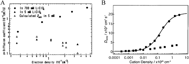 | ||
| Fig. 37 (A) A log–log plot of the empirical diffusion coefficients as a function of TiO2(e−) density. The monotonic increasing trend for the data in 700 mM LiClO4 and the inflection in the 5 mM data can be satisfactorily modeled by the ambipolar diffusion model. Taken from Fig. 5 of ref. 429. (B) A nearly perfect fit of the ambipolar diffusion constant versus the logarithm of the concentration of TBA+ data to the ambipolar diffusion model for a large concentration of TiO2(e−)s (circles); also shown is data at low TiO2(e−) density (squares). Taken from Fig. 3 of ref. 430. | ||
Most measurements of transport times in mesoporous, nanocrystalline TiO2 thin-film electrodes are determined under short-circuit conditions, as elsewhere transport is often RC limited.432 However it is often desirable/necessary to determine these transport times near DSSC working conditions, i.e. near VPP/Voc.413 O’Regan and colleagues have developed a novel method for doing so by measuring photovoltage transients at various preset voltages and entering the results in a zero-free-parameter model.432 Using this novel method it was shown that TiO2(e−) transport though N3/TiO2 thin-film electrodes fits the multiple-trapping model, whereby detrapping limits TiO2(e−) transport and recombination.433 The method also allowed for a more accurate calculation of activation energies for TiO2(e−) transport, as prior methods did not allow for the facile correction of the temperature dependence of Ecb. The results seemed to indicate that the activation energy was not as large as the energy difference between the trap states and the conduction band, consistent with other reports.434–436 Thus the results are in agreement with the aforementioned hopping model proposed by Bisquert where electrons need not fully thermalize to the conduction band in order to hop between trap states within TiO2.403
Following the work of Bisquert and Vikhrenko,415,416 a model employing a quasi-static approximation was proposed that accounted for previously measured activation energies without invoking the temperature dependence of Ecb.437 In contrast, this model predicted concerted and equal shifts in Ecb and the energy of the quasi-Fermi level with temperature.
B Recombination to the oxidized sensitizer
Early studies of TiO2 colloidal solutions and thin films sensitized to visible light with RuII-based and organic sensitizers established that charge recombination to the oxidized sensitizer occurred on a tens- to hundreds-of-microseconds time scale.158,438 The observation of efficient sensitization from compounds with very short excited-state lifetimes, such as [cis-Ru(dcb)2(H2O)2]2+, indicated that excited-state electron injection was a sub-nanosecond process.439 The question then naturally arose: why does such a fortuitous difference in interfacial charge-separation and charge-recombination rate constants exist at the TiO2 interface? For MLCT excited states part of the explanation was that injection occurred from the π* orbitals of a surface-bound, dcb ligand while recombination was to the t2g orbitals of the RuIII-metal center. In other words, there is a built-in type of rectification in these sensitizers whose orbitals provide strong electronic coupling for charge separation but inhibit recombination.218,219 It was also known that charge recombination was in the Marcus inverted region whereas excited-state injection was nearly activationless.438 Such orbital participation and thermodynamics could explain the large difference in interfacial charge-separation and charge-recombination rate constants.Electrochemical investigation of the Eo(RuIII/II) for sensitizers bound to mesoporous, nanocrystalline TiO2 (anatase) thin-film electrodes revealed that by integration of the area under the cyclic voltammogram, ∼10% of the concentration of spectroscopically quantified sensitizers had been oxidized/reduced.72 Although some dyes could directly adsorb to the FTO electrode, this could not wholly explain the ∼10% that were electro-active as this corresponded to over an order-of-magnitude larger surface coverage than was physically possible. It was proposed, for the first time, that self-exchange charge transfer processes across the TiO2 surface could be occurring.
In the first study of lateral hole transfer across the surface of mesoporous, nanocrystalline metal-oxide thin films, a percolation threshold was found to exist.71 This threshold was found to be 50% of saturation surface coverage for phosphonated triarylamines adsorbed onto TiO2, ZrO2, or Al2O3 as determined by chronoabsorption measurements and spectrophotometric Anson plots. The mechanism for this hole transfer was deduced to be via self-exchange hole transfer with eventual mediation by the back TCE support. This process was not limited by the ion motion in solution for the systems studied.
Employing Z907 bound to metal-oxide, thin-film electrodes, it was found that a chemically reversible anodic wave was present on TiO2 and highly insulating Al2O3.440 The percolation threshold was found to be ∼50% of saturation surface coverage and faster lateral hole diffusion coefficients were observed in acetonitrile-based electrolytes versus purely ionic liquids. This was proposed to be due to the two orders-of-magnitude higher viscosity of the ionic liquid that resulted in slower effective ambipolar-diffusion rates. It was also clearly deduced that the increased hole diffusion coefficients for Z907+ and [cis-Ru(dmb)(dcb)(NCS)2]+ under saturation surface coverages were due to efficient hole transfer between isothiocyanate ligands. This was evident by comparison to the slower diffusional, hole-hopping rates for (NC−)2-containing dyes, Ru(bpy)32+-type dyes, dyes with transisothiocyanate ligands, cis-Ru(dmb)(dcb)(NCS)2 with mercury-poisoned isothiocyanate ligands, and N3—whose intermolecular-isothiocyanate ligands are further separated on the surface. The fastest diffusion coefficient for hole transfer was achieved with [cis-Ru(dmb)(dcb)(NCS)2]+ and was determined to be 1.1 × 10⁻⁸ cm2 s−1.
While studying the percolation threshold for three TiO2-bound sensitizers containing donor moieties shown in Fig. 24, it was discovered that one of them exhibited a long-lived photochroism.330 Photochroism occurs when oxidized-donor spectral features are still present even when oxidation of the sensitizer is followed by application of an appropriate bias that could thermodynamically reduce the oxidized donors but not the TiO2 DOS. This was attributed to the extended conjugation of the sensitizer that inhibited its free rotation and the formation of a surface-conducting monolayer. Thus, facile percolation of charge from the back FTO contact to every surface-bound donor could not be realized.
The percolation threshold for Os(bpy)2(dcb)/TiO2 thin-film electrodes was found to be 60% of saturation surface coverage.73 However, at coverages less than the percolation threshold, but with the addition of Ru(bpy)32+ in solution, mediation of oxidative hole transfer occurred upon stepping the potential positive of Eo(RuIII/II). Similarly, addition of Os(bpy)32+ in solution increased the rate of both reductive electron transfer and oxidative hole transfer upon biasing the film in the appropriate direction due to solution-based, dye-mediated charge transfer.
By employing a sensitizer with a lower Eo(RuII/+) than Ecb and relying on ‘hot’-electron injection, laser-flash photolysis of RuII(bpy)2(dcbq)/TiO2 thin films in acetonitrile resulted in immediate, i.e. <10 ns, formation of RuIII(bpy)2(dcbq)/TiO2 and RuII(bpy)2(dcbq−)/TiO2 charge-separated states.135 Fits to stretched exponentials via the KWW function resulted in average rate constants, i.e. τo−1, for [RuII(bpy)2(dcbq−)]+ + [RuIII(bpy)2(dcbq)]3+ recombination of 8 ± 5 × 10⁵ s−1. But a question remained: was recombination predominantly due to electron or hole transfer reactions? By employing chronoabsorption measurements and spectrophotometric Anson plots, the diffusion coefficient for the RuII/+ self-exchange reaction on TiO2 was found to be over an order-of-magnitude larger than that for the RuIII/II reaction. Solution self-exchange rate constants for Ru(bpy)32+ were within a factor of two the same for RuIII/II and RuII/+ in acetonitrile.441–444 It was proposed that the TiO2 DOS mediated electron, but not hole, transfer.
Using RuII(bpy)2(dcbq)/TiO2, FeIII(PPIX)Cl/TiO2 and FeIII(PPIX)(py)2/TiO2 thin-film electrodes, in acetonitrile, methanol, and methanol, respectively, no percolation threshold for electron transfer was observed in TBA+ electrolytes (PPIX is protoporphyrin IX and py is pyridine).445 Interestingly, after being reduced the diffusion coefficients for their oxidation were over two orders-of-magnitude slower for the FeII-based, PPIX coordination compounds. The diffusion coefficient for electron-transfer reduction for each molecular acceptor was at an intermediate value between these two re-oxidation extremes but were within experimental error of one another. This was rationalized based on a Gerischer-type model where the fluctuating energy levels for FeII had a much poorer overlap with the TiO2 DOS as compared to those of dcbq−.
a E o(M+/0) and TiO2 DOS and quasi-Fermi-level dependence. Semiclassical, non-adiabatic Marcus Theory predicts a parabolic-dependence on the logarithm of the electron-transfer rate constant with the standard-state driving force for the reaction.240,446,447 The maximum rate constant occurs at the vertex of this parabola and represents activationless electron transfer and thus should be temperature independent. Electron-transfer processes occurring at larger driving forces are actually slower and are located in an energetic/kinetic region termed the inverted region. Moser and Grätzel reported practically temperature-independent rate constants for charge recombination from colloidal TiO2 to surface-bound, oxidized, organic sensitizers over a >200 degree temperature window.438 Based on numerical simulations employing a quantum-mechanical model for non-adiabatic electron transfer, including an average high-frequency vibrational mode from the sensitizer,305–310 it was shown that under conditions of moderate solvent reorganization energy, practically activationless electron-transfer behavior could be observed well into the Marcus inverted region. Thus, this highly exergonic recombination reaction was concluded to fall deeply within the Marcus kinetic inverted region even though the roughly temperature-independent rate constants eluded to activationless behavior.
Driving-force-dependent electron transfer can be quantified at dye-sensitized TiO2 interfaces where excited-state electron injection into TiO2 leaves an electron at a particular standard-state potential and a “hole” on the sensitizer. The Ecb, and subsequently the free energy of the TiO2(e−)s, can be varied by altering the pH or the concentration of cations, as was employed in excited-state injection studies in section 3/B/ii, while the free energy of the “hole,”i.e.Eo(RuIII/II), can be controlled through synthetic manipulation of the coordinated ligands. Lever has an empirical model that allows these potentials to be accurately determined before the sensitizer is synthesized.448 However, in some cases the environment and the proximity of the sensitizer to the TiO2 surface can in itself result in different measured Eo(RuIII/II)s. Zaban et al. have previously shown that the Eo(RuIII/II) of the RuII(LL)(mpt)CN sensitizer, where LL is 1,2-bis(4′-methyl-bpy-4-yl)ethane and mpt is 4′-phosphonic acid-tpy, became pH-dependent when bound to mesoporous, nanocrystalline TiO2 (anatase) thin films and shifted in a nearly Nernstian fashion in concert with Ecb.313 Similar behavior was also shown for eight other sensitizers who possessed pH-independent Eo(M+/0)s in fluid solution but whose Eo(M+/0) shifted 21 to 53 mV/pH unit when bound to TiO2.312 These sensitizers were either organic or inorganic with metal center being RuII, FeIII or MgII and ligands being tetracarboxyphthalocyaninato-, dcb- or dpb-based, where dpb is 4,4′-diphosphonic acid-bpy. It was proposed that the position of the adsorbed sensitizer within the ionic double layer could explain the differences in shifts of Eo(M+/0) per pH unit.
Employing a family of MLCT sensitizers based on osmium, ruthenium and rhenium whose ground state reduction potential varied by about ∼960 mV, it was shown that recombination kinetics from a TiO2(e−) to an oxidized sensitizer were independent of sensitizer employed.389 The transient data was successfully fit to an equal-concentration, bi-second-order kinetic model on a 100 ns and longer time scale. The data could also be successfully fit to four first-order rate constants but the rationale for this fit was less apparent. Of note was that the raw transient data was insensitive to the sensitizer reduction potential, the molecular geometry, the nature of the metal center employed—i.e. Re, Ru, or Os—and the number of carboxylic acid groups present—i.e. two or four. The insensitivity of the second-order rate constants to these parameters was attributed to the reaction being rate limited by TiO2(e−)-oxidized sensitizer (h+) encounters or lack of change in the apparent driving force for the recombination reaction due to concerted Ecb and ground-state Eo shifts, as was shown previously.312,313 Charge transport within the sensitized film may also have been a second-order process.
In a separate study by Lewis and co-workers, charge recombination to five RuIII or OsIII compounds were fit to the same equal-concentration, bi-second-order recombination model.390 By using the weighted average of the second-order rate constants in conjunction with semiclassical Marcus theory, charge recombination to oxidized sensitizers, like N3+/TiO2, was found to fall in the Marcus inverted kinetic region with a total reorganization energy, λ = ∼1.0 eV, Fig. 38(a). The temperature-dependent electron-transfer kinetics were similar to those observed by Dang and Hupp with Ru-phen based coordination compounds electrostatically bound to colloidal SnO2nanoparticles.449 The kinetics suggested that while nuclear tunneling was negligible, solvent reorganization and low-frequency, metal–ligand vibrational modes assisted the recombination reaction, as opposed to high-frequency, ligand-based vibrational modes. Lewis and co-workers also reported that the activation energy for charge recombination was slightly larger for OsII- versusRuII-based sensitizers.
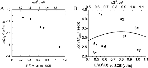 | ||
| Fig. 38 Plot of the logarithm of the inverse of the half-times/lifetimes versus the driving force for two different studies of TiO2(e−) + S+ recombination. The trend in (A) implies that the electron transfer was in the Marcus inverted kinetic region while the trend in (B) seems to follow activationless electron transfer. Taken from Fig. 5 of ref. 390 and Fig. 4 of ref. 450, respectively. | ||
More recently, eight different sensitizers whose Eo(RuIII/II) spanned ∼500 mV were employed to examine the driving-force dependence on charge recombination.450 The transient spectroscopic data was fit to a multiple-trapping, nearest-neighbor CTRW kinetic model by using the KWW function and the driving-force dependence was quantified based on t1/2, the time it took for half of the injected electrons to recombine. Using the inverse of these half-lives the data was shown to be relatively insensitive to variations in Eo(RuIII/II). This was interpreted as being indicative of reactions lying near the peak of the Marcus free energy curve, ΔGo = ∼λ, and with λ = ∼0.8 eV, Fig. 38(b). Therefore, these authors concluded that charge recombination to N3+, and other similar sensitizers, was nearly activationless. It is interesting to note that while the Eo(RuIII/II) values were generally in good agreement with Lewis and colleagues,390 the magnitude of the driving force differed significantly due to discrepancies in the reducing power of the TiO2(e−)s, Fig. 38.
Employing [RuII(depb)3]2+ or [RuII(dpb)3]10−, where depb is 4,4′-diethylphosphonate-bpy bound to mesoporous, nanocrystalline TiO2 (anatase) thin films, the pH dependence of recombination in aqueous solution was studied by Hupp and co-workers.451 The fast exponential component to the biphasic recovery was shown to be invariant of pH (or H0) over a 19 pH-unit range even though the Ecb of TiO2 is known to shift in a nearly Nernstian fashion with pH, Fig. 39(a). One might expect the Eo(RuIII/II) to shift in a concerted fashion as observed by Zaban et al.,312,313 however this was not the case as the Eo(RuIII/II) of the surface-bound sensitizer was shown to have only a minor pH-dependence (5 mV/pH unit) over a >7.5 pH unit range, Fig. 39(b).452 This less than Nernstian-order-of-magnitude shift in Eo(RuIII/II) should have been largely overcome by the potential shift in Ecb. As a continuation of this study, Ru(dpb)2(LL)/TiO2 thin films were shown to exhibit minor, but apparent, Marcus normal region behavior, where LL were bpy and phen derivatives.453 This unexpected result, given the large variations in driving force, was explained as sequential electron- and proton-transfer reactions. It was proposed that the rate-limiting step was back-electron transfer, however this step did not release all of the free energy in the overall reaction, and thus the variation in driving force for this step was solely dependent on changes in Eo(RuIII/II), Fig. 39(c). As the Eo(RuIII/II) differed only slightly with pH, and was actually found to vary with the ζ-potential of the TiO2, only a small deviation in driving force was actually realized.
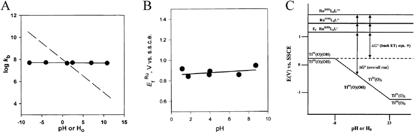 | ||
| Fig. 39 (A) Plot of the logarithm of recombination rate constant versus pH for TiO2 thin films. As the energy of the conduction band edge, Ecb, shifts in a nearly Nernstian fashion with pH (dashed line), this plot illustrates driving-force independent recombination rates (solid line with points). Taken from Fig. 4 of ref. 451. (B) Plot of the standard-state reduction potential of the surface-bound compounds (Eo(RuIII/II)) versus the pH, confirming that the E0(RuIII/II) did not change with the pH of the solution and thus further supporting the driving-force independent mechanism. Taken from Fig. 5 of ref. 452. (C) Pourbaix-type diagram of the TiO2(e−) + S+ recombination reaction. The driving-force independent recombination rates were rationalized as being due to rate-limiting electron transfer followed by exergonic proton transfer. Taken from Fig. 5 of ref. 453. | ||
The described charge-recombination studies with altered thermodynamic driving force provide a somewhat conflicting series of conclusions: rate constants independent of the ground-state reduction potential of the sensitizer, in the inverted region, and near the top of the Marcus curve. Undoubtedly, these differences arise from details of the preparation of the TiO2 thin films, surface chemistry such as TiCl4 pretreatments,454 and species present in the electrolyte. Additional research is required to identify the critical variables, especially in non-aqueous electrolytes.
While the driving-force dependence for charge recombination to the oxidized sensitizer in mesoporous, nanocrystalline thin films is not completely established, the behavior in aqueous colloidal solutions appears to be more clear. Hupp and co-workers monitored charge recombination to six different Fe(CN)5(L)n− sensitizers bound to colloidal TiO2 in aqueous pH 2 solution on a nanosecond time scale.304 The recombination kinetics were found to be biphasic with a fast first-order component followed by longer non-exponential kinetics. The first-order component varied with Eo(FeIII/II) as expected if the process were occurring in the Marcus inverted region. Likewise, recombination reactions from electrostatically bound RuII- and OsII-polypyridyl coordination compounds to colloidal SnO2nanoparticles exhibited a pH-sensitive kinetic behavior.455 This is in stark contrast to the pH-independent behavior observed for recombination from similar compounds covalently anchored to mesoporous, nanocrystalline TiO2 (anatase) thin films. It was suggested that this difference was due to the significant trap density in TiO2 and that ionic attachment introduced fewer surface traps.
As with studies on charge separation of section 3/B/ii, it is also useful to study charge recombination under steady-state, working conditions at short circuit. The first account of such a study was performed by Grätzel and co-workers in 1990.158 By exciting at least a quarter of the sensitizers on Ru(dcb)3/TiO2 thin-film electrodes in LiClO4 aqueous electrolytes it was shown that the half-times for the non-exponential recombination kinetics decreased by almost three orders of magnitude under forward-bias versus reverse-bias conditions. This same increase in rate was found for N3/TiO2 thin-film electrodes in ethylene carbonate–propylene carbonate (1 : 1) solution as the irradiance was increased to generate ∼1 to ∼50 TiO2(e−)s/particle.456 The kinetics were fit to the multiple-trapping, nearest-neighbor CTRW model and KWW function. The half-times were invariant on irradiance when <1 TiO2(e−)/particle was generated.
Durrant and co-workers showed the half-time for N3++TiO2(e−) recombination exhibited an exponential dependence on applied voltage in 0.1 M TBA+ trifluoromethanesulfonate ethanol electrolyte, Fig. 40(a).457 When immersed in ethanol electrolytes and on applying an electrochemical bias from +100 to −600 V vs.Ag/AgCl, the half-time for the recombination reaction decreased by more than seven orders of magnitude while the injection yield remained unchanged.456 By changing the electrolyte from ethanol/TBAT (Electrolyte A), where TBAT is tetrabutylammonium triflate, to CH3CN/TBAClO4/LiClO4 (Electrolyte B) and then adding 4-tert-butylpyridine (Electrolyte C), similar bias-dependent, TiO2(e−) recombination rates were observable but, again, only under conditions of >1 TiO2(e−)/particle, Fig. 40(b). However, when comparing Electrolyte A to B at different biases, their half-times for recombination differed to varying degrees, but with the half-time in Electrolyte B always being larger. As the driving force for recombination would decrease in the presence of Li+ due to the positive shift in Ecb, this data does not fit that of Marcus inverted behavior. Additionally, the multiple-trapping, nearest-neighbor CTRW model for recombination was further supported over a bi-second-order model.254,389,390 The greater than seven orders-of-magnitude decrease in half-time would result in approximately the same increase in initial rate. Given the proposed second-order process, the differential rate law v = k2[TiO2(e−)][S+] would require the generation of 107 TiO2(e−)s/particle which was highly improbable based on the magnitude of spectroscopic signals and approximate extinction coefficients.
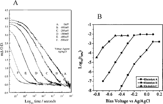 | ||
| Fig. 40 (A) Bias-dependent, time-resolved, single-wavelength absorption difference spectra for N3/TiO2 thin film electrodes indicating that as the density of acceptor states in the TiO2electrode were filled, the rate of TiO2(e−)+N3+ recombination increased. Applied biases are indicated on the figure. Taken from Fig. 2 of ref. 457. (B) Plot of the logarithm of the recombination half-life versus the applied bias in the indicated electrolytes. See text for electrolyte compositions. Taken from Fig. 6 of ref. 456. | ||
Although the rate of charge recombination of TiO2(e−)s and N3+ was dependent on the concentration of electrochemically generated TiO2(e−)s, this was not the case for regeneration by the solution redox mediator.382 At moderate LiI concentration, i.e. 30 mM, and at an applied bias approximately equal to the Voc under 1 sun, AM1.5-simulated conditions, the kinetic partitioning between TiO2(e−)s + N3+ recombination and regeneration of N3+ by the reduced solution redox mediator were similar. But under the typical DSSC conditions of 0.5 M LiI and 0.05 M I2 and 1 sun, AM1.5-simulated irradiance, the rate of sensitizer regeneration would be greatly favored and TiO2(e−)s + N3+ recombination would not limit performance.
b Distance dependence. Distance-dependent electron tunneling behavior can be studied for recombination from a TiO2(e−) to an oxidized surface-bound acceptor. Rate constants due to tunneling should exhibit an exponential dependence on distance, eqn (8), as was the case for electron-injection tunneling behavior in section 3/B/iii.
Three novel sensitizers bound to TiO2via an mpt ligand and containing a nearby triarylamine donor moiety were studied in order to determine the distance dependence for recombination, Fig. 24.330 The donor nitrogen atoms were calculated to be 12 Å, 18 Å, and 24 Å from the surface. Assuming the typical dampening factor, β = 1.2 Å−1, for ‘through space’ electronic coupling between the TiO2(e−)s and NAr3+, the expected 6 Å-distance dependence was not observed and was off by a factor of three. It was thought that this was due to the fact that the dyes may not bind exactly in a perpendicular orientation to the surface.
Employing three RuII sensitizers containing a bpy ligand derivatized with zero, one or two oligo(xylylene) linkers, the distance dependence of TiO2(e−) recombination was studied.267 By comparing the weighted average of the bi-second-order rate constants390 differences in back-electron-transfer rate constants were found to be within experimental error of one another. As was the case with electron injection, the lack of expected large differences in rate constant were proposed to result from variable Ru–TiO2 distances due to the flexibility of the linker groups.
The distance dependence of back-electron transfer was examined in acetonitrile for three rigid-rod Ru(bpy)32+-based sensitizers containing zero, one, two, or three rigid phenyleneethynylene linkers covalently attached to TiO2via two methyl ester anchoring groups.268,458 It was shown that recombination kinetics from a TiO2(e−) to RuIII were successfully fit by an equal-concentration, bi-second-order kinetic model254,389,390 and that the average of the rate constants was essentially independent of sensitizer employed. Thus, the expected distance dependence for the rate of back-electron transfer was not observed. This was partially supported by the fact that sensitizers lacking binding groups were still found to bind to TiO2 indicating that expected Ru–TiO2 distances may be incorrect due to alternative binding orientations.
Durrant and colleagues studied Ru(4,4′-(R)2-bpy)(dcb)2/TiO2 thin films, where R contained oligo(NPh3) groups at varying distances from the RuII-metal center, to determine the distance dependence for back-electron transfer.332 After combining this data with other data from their laboratories,253,331,450,459 it was clearly evident that the TiO2(e−) back-electron transfer rate constants displayed an exponential dependence on spatial separation with dampening factor, β = 0.95 ± 0.2 Å−1. Additionally, cis-Ru(4,4′-vinyl(NPh3)n-bpy)(dcb)(NCS)2 (n = 1, 2) were synthesized and DFT calculations suggested that their HOMOs resided predominantly on the NPh3 moieties at a distance of 10.5 and 11.6 Å, respectively.460 When compared to Z907/TiO2, these dyes exhibited larger t1/2, i.e. 0.22, 1.8, 3 ms for Z907, n = 1, and n = 2, respectively, that followed the expected exponential trend.
Using the mono-phosphonated version of the ‘black dye,’ [Ru(mpt)(NCS)3]3−, bound to the same TiO2/Al2O3 core–shell particles mentioned above for electron injection, Fig. 16(a), the distance dependence of TiO2(e−) recombination was studied.271 Tunneling was required for electron recombination and the kinetics were non-exponential with half-times ranging from 6 μs to 60 ms for 0 to 6 nm thick Al2O3 overlayers, Fig. 41(a). Using signal half-times it was shown that charge recombination of TiO2(e−)s/Al2O3 and [Ru(mpt)(NCS)3]+ resulted in a dampening factor, β = 0.15 Å−1, Fig. 41(b). This result, combined with the predominant dampening factor for injection, β = 0.11 Å−1, illustrates that recombination is attenuated to a greater degree than injection when TiO2/Al2O3 core-shell designs are employed. The approximately six-times-smaller dampening factor when compared to the results from the molecular approach used by Durrant and co-workers suggests that intra-bandgap states within the Al2O3 coating could be present and mediating this back-electron transfer.
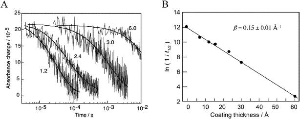 | ||
| Fig. 41 (A) Time-resolved, single-wavelength absorption difference spectra for Ru(4′-PO32−-tpy)(NCS)3/TiO2 thin films illustrating that the rate of recombination was inversely related to the size of the Al2O3 overlayer illustrated in Fig. 16(a). Al2O3 overlayer thickness in nanometers are shown. (B) Plot of the natural logarithm of the recombination half-life versus the Al2O3 coating thickness illustrating tunneling behavior. Taken from Fig. 8 and 9, respectively, of ref. 271. | ||
As mentioned above, Haque, Durrant, and colleagues significantly increased the charge-separated lifetime to over 4 s by employing a Ru(4,4′-(R)2-bpy)(dcb)2/TiO2 system, where R contained a poly(vinyl-NPh3) group of about 100 units, Fig. 25(b).332 The half-times for the charge-separated state increased from 350 μs to 5 ms to 4 s as the number of vinyl-NPh3 subunits increased from 1 to 2 to 100, respectively. Also, when fit to the multiple-trapping, nearest-neighbor CTRW model and the KWW function, the dampening factor ranged from 0.4 to 0.9 to 1, respectively; the latter indicating a mono-exponential, first-order recombination mechanism, Fig. 42.
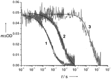 | ||
| Fig. 42 Time-resolved, single-wavelength absorption difference spectra for Ru(4,4′-(R)2-bpy)(dcb)2/TiO2 thin films, where R contained one triphenylamine (NPh3) group (1), two NPh3 groups (2), or a poly(vinyl-NPh3) group of about 100 units (3), as depicted in Fig. 25(b). Taken from Fig. 2 of ref. 332. | ||
Clifford et al. analyzed two free-base porphyrin sensitizers, meso-5,10,15,20-tetrakis(4-carboxyphenyl)porphyrin and meso-5-(4-carboxyphenyl)-10,15,20-tris(4-diphenylaminophenyl)porphyrin, by transient absorption spectroscopy and found that TiO2(e−) recombination with the oxidized porphyrin ring was sufficiently slowed for the latter sensitizer.461 The former sensitizer’s kinetics were satisfactorily fit to the multiple-trapping, nearest-neighbor CTRW model and the KWW function, β = 0.31, whereas the kinetics for the latter sensitizer were perfectly first order in nature, i.e. β = 1, Fig. 43(a). This was believed to be due to a different rate-limiting step for recombination between each oxidized sensitizer and the TiO2(e−)s. While detrapping was rate limiting for the former dye, the final TiO2(e−) + S+ electron-transfer step limited the latter. The explanation for a first-order rate constant, and not an equal-concentration, second-order rate constant, was that the intrinsic concentration of TiO2(e−)s was much larger than the additional concentration resulting from sensitizer, excited-state injection.182 Thus, as the concentration of oxidized sensitizers decreased due to TiO2(e−) + S+ recombination, the TiO2(e−) concentration changed little resulting in the observed pseudo-first-order kinetic behavior.
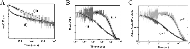 | ||
| Fig. 43 Time-resolved, single-wavelength absorption difference spectra for two free-base porphyrin sensitizers, meso-5,10,15,20-tetrakis(4-carboxyphenyl)porphyrin (i, dye 1) and meso-5-(4-carboxyphenyl)-10,15,20-tris(4-diphenylaminophenyl)porphyrin (ii, dye 2), bound to TiO2 thin films illustrating that the recombination kinetics were dispersive, and could be fit to the multiple-trapping, nearest-neighbor CTRW model of Nelson et al., and a first-order kinetic mechanism, respectively. (A) The data is displayed as the logarithm of the ΔAbsorbance versus the time to illustrate the first-order nature of the latter sensitizer’s kinetics, i.e. ii, dye 2. Taken from Fig. 1(b) of ref. 461. (B) The same data displayed as the ΔAbsorbance versus the logarithm of the time to illustrate the dispersive nature of the former sensitizer’s kinetics, i.e. i, dye 1. Taken from Fig. 1(a) of ref. 461. (C) The same data and plot as in B but fit equally as well to the new Coulomb-trap, random-flight multiple-trapping model of Tachiya and colleagues. Taken from Fig. 4 of ref. 462. | ||
The back-electron transfer kinetics for two RuII-based sensitizers were compared: N719 and a novel sensitizer with a covalently bound triarylamine donor where the hole was efficiently transferred away from TiO2 within the instrument response time.331 As was seen by Clifford et al. the kinetics of the faster back-electron transfer from N719 were dispersive while the slower kinetics for the novel sensitizer were first order in nature.
Tachiya and colleagues proposed the Coulomb trap model for back-electron transfer to oxidized sensitizers which employs the random-flight multiple-trapping model for TiO2(e−) transport.462 The model is based on the idea that a TiO2(e−) only feels the Coulombic attraction to a dye cation when it is trapped near the cation. This stabilization interaction effectively increases the activation energy for the detrapping not only of said TiO2(e−) but of neighboring TiO2(e−)s as well. By employing an exponential TiO2 DOS that are pre-filled to a reasonable dark concentration of TiO2(e−)s, i.e. 0.1 per particle,166 and assuming that the effective dielectric constant at the site of this Coulombic attraction is low, i.e. <5, the experimental data of Clifford et al. can be modeled extremely well. Fig. 43(b)/(c) illustrates the comparison of the two models: the multiple-trapping, nearest-neighbor CTRW model by Nelson et al. in the middle, b, and the new Coulomb-trap, random-flight multiple-trapping model by Tachiya and colleagues on the right, c.
C Recombination to acceptors in solution
Measurements of Voc provide an indirect, but powerful, tool for characterizing charge recombination processes. Although the Voc is the maximum Gibbs free energy that one can obtain from a regenerative solar cell, it can often be kinetically derived under steady-state, illumination conditions. The modified diode equation is often found to be relevant for DSSCs:
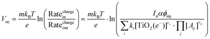 | (16) |
An early application of this to DSSCs was observed with the intramolecular charge separation as previously described,328 where the Voc was measured for Ru(dmb)(dcb)2/TiO2 and Ru(4-CH3, 4′-CH2-PTZ-bpy)(dcb)2/TiO2 thin film electrodes as a function of irradiance in 0.1 M LiClO4 or NaI/I2 (0.5/0.05 M) propylene carbonate electrolytes. The potentials measured versus a Ag+/Ag pseudo-reference electrode indicated that the Voc was 175 ± 10 mV larger for Ru(4-CH3, 4′-CH2-PTZ-bpy)(dcb)2/TiO2versusRu(dmb)(dcb)2/TiO2. The photocurrents were approximately the same for both sensitizers over four orders-of-magnitude irradiance indicating that the numerator of eqn (16) was sensitizer independent while the denominator was not. The charge recombination rate constants were measured spectroscopically, k = 3.9 × 10⁶ s−1 and k = 3.6 × 10³ s−1, respectively. With these rate constants a ΔVoc of ∼200 mV was calculated which is close to the value 175 ± 10 mV that was measured experimentally. Remarkably, these molecular interfaces behaved as ideal diodes, m = 1, over this four orders-of-magnitude change in irradiance. Interestingly in the presence of the redox mediator, i.e. I3−/I−, the non-ideality factor was 2. The Voc remained larger for Ru(4-CH3, 4′-CH2-PTZ-bpy)(dcb)2/TiO2 suggesting that charge recombination to oxidized iodide products was also inhibited for this compound. More recently, we have obtained experimental evidence that there may indeed be an advantage in oxidizing iodide farther from the TiO2 surface. In dichloromethane electrolytes containing 0.1/0.005 M TBAI/I2, the Voc was found to be directly related to the distance the hole was from the surface.471 Using [Ru(bpy)2(deeb)]2+ or tripodal, Ru(bpy)32+-based sensitizers containing one or two rigid phenyleneethynylene linkers covalently attached to a 1,3,5,7-tetraphenyladamantane core and attached to the TiO2 surface in a tripodal-shaped binding configuration, the distance between the RuIII-metal center and the TiO2 surface was varied.268,269,471 As ion-pairing was previously shown to occur in dichloromethane with [Ru(bpy)2(deeb)]2+ and I− or I3−,133,357,472 it was proposed that after ion-paired I− photo-oxidation, TiO2(e−) recombination may occur to ion-paired I3− at a fixed distance from the surface. Assuming the injection yield was invariant on the length of the spacer, the Voc data highly supported this distance-dependent recombination mechanism, Fig. 44.
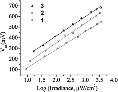 | ||
| Fig. 44 Plot of Vocversus the logarithm of the irradiance for three TiO2-bound, Ru(bpy)32+-based sensitizers containing one (circles) or two (triangles) rigid phenyleneethynylene linkers covalently attached to a 1,3,5,7-tetraphenyladamantane core or simply a deeb ligand (squares) in 0.1/0.005 M TBAI/I2dichloromethane electrolyte. The farther the RuII-metal center, and thus proposed ion-paired I− and/or I3−, from the TiO2 surface, the longer the lifetime of the charge-separated state and thus increased Voc. Taken from Fig. 3 of ref. 471. | ||
In early studies with a series of cis-Ru(dcb)2X2/TiO2 thin film electrodes (M = Ru, Os), the intensity-dependent photocurrent and Voc values could generally be rationalized based on the redox properties of the compound. The Voc was never found to be sensitizer dependent. However, recently there is some evidence that the recombination rate constants can be tuned through the π* levels of the sensitizer and halide coordination sites on macrocyclic compounds.285,470 Indeed any time large photocurrents and small Voc values are measured, it is of interest and suggests that there remains some charge-recombination pathway to the sensitized interface. Arakawa and co-workers, and more recently Bignozzi and colleagues, have identified such conditions with RuII and OsII compounds that have diimine ligands with low-lying π* levels.469,470 Recall, too, that if Ecb is raised, the photogenerated TiO2(e−)s can be fully trapped on dcbq ligands,299 behavior that is consistent with that reported here.
However, in order to calculate the Voc, the absorbed photon flux, Ioα, the DOS non-ideality factor, m, the injection yield, ϕinj, and the TiO2(e−) recombination rate based on the overall recombination mechanism—the denominator within the Napierian logarithm—need be determined.464–468 For the reasons previously discussed, there are no accepted and straightforward means of measuring the denominator as even the chemical identity of the acceptor is unknown, much less the mechanism by which it reacts. Doing this is no simple task given the numerous possible reaction intermediates, as depicted in Scheme 1 in section 4/B/i/a. The elementary reaction steps that have been proposed thus far are:
| I− + I2⇌ I3− | (9, restated) |
| I2 + TiO2(e−) → I2˙− | (17††) |
| 2I2˙−→ I3− + I− | (18a‡‡) |
| I2˙− + TiO2(e−) → 2I− | (18b§§) |
| I2⇌ 2Iads˙ | (19) |
| Iads˙ + TiO2(e−) → I− | (20) |
| TiO2(e−)trapped⇌ TiO2(e−)free | (21) |
| TiO2(e−)free→ TiO2(e−)reactive | (22) |
| X + TiO2(e−)reactive→ X− | (23) |
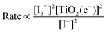 | (24a) |
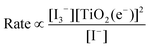 | (24b) |
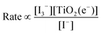 | (24c) |
 | (24d) |
 | (24e) |
| Eqn | Order in: | Comments | ||
|---|---|---|---|---|
| [I3−] | TiO2(e−) | [I−] | ||
| (24a) | 2 | 2 | −2 | Reaction (9) is in pre-equilibrium, reaction (17) is fast, and reaction (18a) is the rate-determining step. |
| (24b) | 1 | 2 | −1 | Reaction (9) is in pre-equilibrium, reaction (17) is fast, and reaction (18b) is the rate-determining step. |
| (24c) | 1 | 1 | −1 | Reaction (9) is in pre-equilibrium and reaction (17) is the rate-determining step. |
| (24d) | 0.5 | 1 | −0.5 | Reaction (9) is in pre-equilibrium, reaction (19) is fast, and reaction (20) is the rate-determining step. |
| (24e) | 0 | 1 | 0 | Reaction (21) is rate determining and reactions (22) and (23) follow. |
As is apparent, unambiguous determination of the integrated rate law and overall reaction mechanism requires knowledge of the reaction order for not just one, but two species. Thus, certain experiments alone cannot irrefutably establish the overall mechanism. Unfortunately, the current body of literature paints a somewhat conflicting story and thus results from the literature will be explained according to which of the five integrated rate laws and reaction mechanisms above could apply, i.e.eqn (24a–e).
a Electrochemical techniques. Peter and colleagues studied N3/TiO2 DSSCs in acetonitrile electrolyte by IMVS/IMPS, a novel potentiostatic–galvanostatic–potentiostatic (PGP) method, and transient photovoltage/photocurrent measurements while under background illumination. Based on an inverse-square root relationship of the TiO2(e−) lifetime, τn, and background light intensity, i.e. τn∝Io−0.51, it was deduced that the recombination reaction of TiO2(e−)s with the I3−/I−redox mediator was second order in TiO2(e−) density, i.e. 1/0.51, and thus an I2˙− intermediate was proposed.223,473 This is indicative of mechanism (24a) or (24b). The same conclusion was drawn from the PGP method where the DSSCs were illuminated with a blue-light-emitting diode under open-circuit conditions and then were rapidly short circuited for chronocoulometric measurements.474–476 The pseudo-second-order rate constant from the IMVS and PGP measurements was determined to be 0.6 and 1.1 × 10⁴ M−1 s−1 at 50 mM I3−, respectively. Unfortunately, a non-inverse-square root relationship between τn and the isc at various green-light laser irradiances, i.e. τn∝isc−0.62, was also determined by transient photovoltage/photocurrent measurements.477 Explanations of the results were that either recombination is not first order in TiO2(e−)s or the interfacial electron-transfer rate constant depends on trap occupancy and/or the rate of TiO2(e−) diffusion. An explanation for the apparent discrepancy among experimental results may be the variations in the background/initial photon fluxes employed: effectively <0.2, 1 and <0.01 suns, AM1.5-simulated conditions, respectively. In none of these studies was the order of the reaction with respect to I2˙−, I3−, I− or I2 concentration explored.
Frank and co-workers studied N3/TiO2 DSSCs in acetonitrile–NMO (50 : 50 wt%) electrolyte, where NMO is 3-methyl-2-oxazolidinone, and by two procedures found a second-order dependence on I3−: plots of Vocversus the concentration of I3− and IMVS in the presence of two different I3−/I− concentrations.464,478,479 The light-intensity, power-law dependence of the lifetime, as determined by IMVS and IMPS, was modeled to be the order of the reaction in TiO2(e−)s and was approximated to be second order based on the calculated powers of ∼2.2 and ∼2.7, respectively. The results are consistent with mechanism (24a). These same authors studied N719/TiO2 DSSCs in 3-methoxypropionitrile electrolyte and deduced that recombination was TiO2(e−)-diffusion limited.480 These conclusions were based on a model of TiO2(e−)-diffusion-limited recombination and fits to transient photovoltage and photocurrent data as a function of background white-light intensity ranging approximately three orders-of-magnitude in irradiance up to ∼1 sun. This data was more consistent with mechanism (24c), (24d) or (24e).
By measuring the photovoltage under conditions of up to 0.82 suns illumination and in the presence of varied concentrations of I3− for N3/TiO2 DSSCs in nitrile electrolyte, Hagfeldt and co-workers determined the recombination reaction to be first order in I3−.481 They proposed the alternative mechanism (24b) with elementary steps (17)†† and (18b).§§ Although the reaction order with respect to the density of TiO2(e−)s was not determined, mechanism (24c) was unlikely due to the high irradiances employed. The difference between these results and those of Frank and co-workers was rationalized by the solvent composition: 0 versus 50 wt% NMO, respectively, where it was proposed that NMO prevented reaction (17)†† from occurring, in favor of reaction (17). The diode-equation non-ideality factor was calculated to be very close to one, i.e. 1.08, but could be in error based on somewhat condition-dependent values often cited in the literature, i.e.∼1.7–3.8.171,178,183–185,223,224 Such error could be due to the fact that the non-ideality factor was obtained from Vocversus light intensity plots and was calculated based on the unlikely assumptions that the injection yield and TiO2(e−) recombination rate were independent of the irradiance.254 Due to the inverse relationship between non-ideality factor and reaction order in I3− for this model, a non-ideality factor of 2 would have resulted in a reaction order in I3− of 0.5, consistent with mechanism (24d).
b Spectroscopic techniques. Hagfeldt and co-workers employed nanosecond transient absorption spectroscopy to study iodide turnover and regeneration from ‘black dye’/TiO2 thin films in 3-methoxypropionitrile containing 0.5 M LiI and 50 mM I2.482 The reduction of ‘black dye’+/TiO2 by iodide resulted in the formation of I2˙−, which occurred in <20 ns. At higher irradiances, the transient spectroscopic signal for I2˙− and TiO2(e−)s at 760 nm decayed with a half-time of ∼100 attributed to TiO2(e−) + I2˙− recombination (eqn (18b)). This suggested mechanism (24b) was highly likely. The first phase of the overall biphasic kinetics were fit to an equal-concentration, second-order integrated rate law with a non-zero baseline, but with much error in the extracted rate constant. The equal-concentration, second-order kinetics were believed to be present due to equal concentrations of I2˙− and TiO2(e−)s formed after pulsed-light excitation via reaction (11) or equal concentrations of I˙ and TiO2(e−)s formed via reaction (10) followed by rapid and quantitative I2˙− formation via reaction (25):
| I− + I˙→ I2˙− | (25) |
Nelson et al. predicted a sublinear power-law variation of TiO2(e−) density with light intensity, i.e. n = CIoβ, and deduced that the recombination reaction would be first order in the density of TiO2(e−)s at low light intensities, indicative of mechanism (24c), (24d) or (24e).182,185 The former result has been previously observed479 and the latter behavior was seen above with recombination of TiO2(e−)s and oxidized sensitizers in section 5/B/ii/b.331,461 Using transient absorption spectroscopy and N3/TiO2 thin-film electrodes in propylene carbonate electrolyte containing iodide, Durrant, Nelson, and co-workers monitored the kinetics for the loss of I2˙−.382 After photo-excitation of ∼1% of the sensitizers, electron injection into TiO2, and hole transfer to iodide, I2˙− was proposed to be formed by (11) or (10) followed by reaction (25). As evidenced by studies performed under variable-applied bias conditions, the rate of I2˙− loss was determined to be second order in the concentration of I2˙− and 0th order in TiO2(e−) density consistent with the I2˙− dismutation reaction (18a). It was noted that the TiO2(e−)s most likely recombined with I3− or I2 in a latter step but that neither species could be unambiguously identified in the spectra. Thus, this experiment modeled the fate of I2˙− but did not detail the reaction of the TiO2(e−)s, which may be more relevant to the functioning DSSC. However, a mechanism consistent with (24a) could be deduced.
Durrant, Nelson, and co-workers studied the recombination kinetics for TiO2(e−)s with I2 by transient absorption spectroscopy on unsensitized TiO2 thin films in acetonitrile electrolytes by monitoring the loss of TiO2(e−)s after their formation by bandgap excitation and subsequent sacrificial hole scavenging with MeOH or Fe(CN)64−.463 By transiently generating <13 TiO2(e−)s/particle, it was shown that in the limit of a high concentration of I2, the TiO2(e−) kinetics followed the multiple-trapping, nearest-neighbor CTRW model and KWW function observed for trap-limited recombination. In the limit of a low concentration of I2 the kinetics became mono-exponential, as predicted by the dispersive, electron-transfer theory when heterogeneous electron transfer is limited by the concentration of acceptors, Fig. 45. Based on Monte Carlo simulations performed to mimic this behavior and a plot of half-lives versus the concentration of I2, second-order processes were ruled out. The kinetics for the loss of TiO2(e−)s in the presence of 50 mM I2 was found to be over two orders-of-magnitude faster in the absence of 0.7 M LiI, and more dispersive. Given the strongly favorable equilibrium of I2 + I−→ I3− in acetonitrile, Keq > 106 M−1 (eqn (9)),344–349 this implies that I2 is a better acceptor than I3− for TiO2(e−)s in acetonitrile. The lack of any signal for I2˙− during recombination implied that the reaction mechanism for the loss of TiO2(e−)s to the I3−/I−redox mediator on unsensitized TiO2 thin films is analogous to the same reaction at the platinum counter electrode, i.e. dissociative adsorption followed by electron transfer and mechanism (24d).
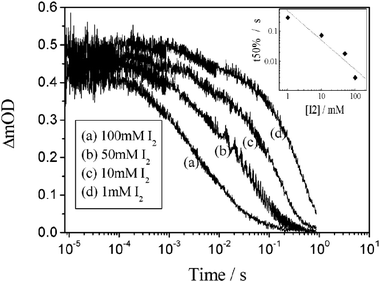 | ||
| Fig. 45 Time-resolved, single-wavelength absorption difference spectra for unsensitized TiO2 thin films as a function of I2 concentration. Inset: A log–log plot of the half-life versus the concentration of I2 illustrating the proposed first-order recombination behavior in the concentration of I2. Taken from Fig. 5 of ref. 463. | ||
6. Conclusions
It has been eighteen years since the celebrated Grätzel and O’Regan paper first appeared in Nature. This review demonstrates the tremendous progress that has been made towards developing a molecular-level understanding of charge-transfer processes at sensitized TiO2 interfaces. The time scales and dynamics for excited-state electron injection into TiO2 have been quantified precisely under many experimental conditions. Regeneration of the photo-oxidized sensitizer by a variety of outer-sphere electron donors, including iodide, has also been quantified in some detail. Much less progress has been made towards our understanding of the unwanted charge recombination to oxidized iodide species, i.e. TiO2(e−) + A. This is at least in part due to the inefficiency of these processes which makes characterization difficult. Fundamental data on the identity of the Acceptor(s) as well as the reduction mechanism(s) are still lacking. Nevertheless, studies have shown that the sensitizer π* orbitals and charged ions in the electrolytes can play specific roles. Given the recent breakthroughs and the keen interest in these reactions, rapid progress is expected. A molecular-level understanding of the mechanisms for charge separation and recombination at sensitized semiconductor interfaces may ultimately enable optimal light-to-electrical power conversion in DSSCs and in future-generation photovoltaics.Acknowledgements
The Division of Chemical Sciences, Office of Basic Energy Sciences, Office of Energy Research, U.S. Department of Energy, the National Science Foundation, and the donors of the Petroleum Research Fund, administered by the ACS, are gratefully acknowledged for research support.References
- M. I. Hoffert, K. Caldeira, A. K. Jain, E. F. Haites, L. D. D. Harvey, S. D. Potter, M. E. Schlesinger, S. H. Schneider, R. G. Watts, T. M. L. Wigley and D. J. Wuebbles, Nature, 1998, 395, 881–884 CrossRef CAS.
- K. Caldeira, A. K. Jain and M. I. Hoffert, Science, 2003, 299, 2052–2054 CrossRef CAS.
- United States, Department of Energy, Energy Information Administration, http://www.eia.doe.gov/.
- N. S. Lewis and D. G. Nocera, Proc. Natl. Acad. Sci. U. S. A., 2006, 103, 15729–15735 CrossRef CAS.
- D. Lüthi, M. Le Floch, B. Bereiter, T. Blunier, J.-M. Barnola, U. Siegenthaler, D. Raynaud, J. Jouzel, H. Fischer, K. Kawamura and T. F. Stocker, Nature, 2008, 453, 379–382 CrossRef.
- L. Loulergue, A. Schilt, R. Spahni, V. Masson-Delmotte, T. Blunier, B. Lemieux, J.-M. Barnola, D. Raynaud, T. F. Stocker and J. Chappellaz, Nature, 2008, 453, 383–386 CrossRef CAS.
- Lewis, Nathan S., Powering the Planet—Global Energy Perspective, http://nsl.caltech.edu/energy.html.
- Department of Energy, Report of the Basic Energy Sciences Workshop on Solar Energy Utilization, Washington, DC, 2005 Search PubMed.
- United Nations, World Energy Assessment Report: Energy and the Challenge of Sustainability, New York, NY, 2003 Search PubMed.
- B. O’Regan and M. Grätzel, Nature, 1991, 353, 737–740 CrossRef CAS.
- A. Hagfeldt and M. Grätzel, Chem. Rev., 1995, 95, 49–68 CrossRef CAS.
- M. A. Green, K. Emery, Y. Hishikawa and W. Warta, Progress in Photovoltaics: Research and Applications, 2008, 16, 61–67 Search PubMed.
- A. Hagfeldt and M. Grätzel, Acc. Chem. Res., 2000, 33, 269–277 CrossRef CAS.
- M. Grätzel, in a talk at the 12th International Conference on Photochemical Conversion and Storage of Solar Energy, Berlin, Germany, August, 1998.
- N. Papageorgiou, Coord. Chem. Rev., 2004, 248, 1421–1446 CrossRef CAS.
- J. van de Lagemaat, K. Zhu, K. D. Benkstein and A. J. Frank, Inorg. Chim. Acta, 2008, 361, 620–626 CrossRef CAS.
- A. J. Frank, N. Kopidakis and J. v. d. Lagemaat, Coord. Chem. Rev., 2004, 248, 1165–1179 CrossRef CAS.
- L. M. Peter, Phys. Chem. Chem. Phys., 2007, 9, 2630–2642 RSC.
- J. Bisquert, Phys. Chem. Chem. Phys., 2008, 10, 3175–3194 RSC.
- J. Bisquert, Phys. Chem. Chem. Phys., 2008, 10, 49–72 RSC.
- National Renewable Energy Laboratory, Reference Solar Spectral Irradiance: Air Mass 1.5, http://rredc.nrel.gov/solar/spectra/am1.5/.
- K. Laqua, W. H. Melhuish and M. Zander, Pure Appl. Chem., 1988, 60, 1449–1460 CrossRef CAS.
- G. M. Hasselman, D. F. Watson, J. R. Stromberg, D. F. Bocian, D. Holten, J. S. Lindsey and G. J. Meyer, J. Phys. Chem. B, 2006, 110, 25430–25440 CrossRef CAS.
- G. P. Smestad and M. Grätzel, J. Chem. Educ., 1998, 75, 752–756 CrossRef CAS.
- M. K. Nazeeruddin, A. Kay, I. Rodicio, R. Humphry-Baker, E. Mueller, P. Liska, N. Vlachopoulos and M. Grätzel, J. Am. Chem. Soc., 1993, 115, 6382–6390 CrossRef CAS.
- M. Grätzel, J. Photochem. Photobiol. C: Photochem. Rev., 2003, 4, 145–153 CrossRef CAS.
- J. P. Paris and W. W. Brandt, J. Am. Chem. Soc., 1959, 81, 5001–5002 CrossRef CAS.
- F. E. Lytle and D. M. Hercules, J. Am. Chem. Soc., 1969, 91, 253–257 CrossRef CAS.
- F. Felix, J. Ferguson, H. U. Guedel and A. Ludi, J. Am. Chem. Soc., 1980, 102, 4096–4102 CrossRef CAS.
- G. A. Crosby, K. W. Hipps and W. H. Elfring, J. Am. Chem. Soc., 1974, 96, 629–630 CrossRef CAS.
- E. M. Kober and T. J. Meyer, Inorg. Chem., 1982, 21, 3967–3977 CrossRef CAS.
- E. U. Condon, Phys. Rev., 1928, 32, 858–872 CrossRef CAS.
- E. Condon, Phys. Rev., 1926, 28, 1182–1201 CrossRef CAS.
- J. Franck and E. G. Dymond, Trans. Faraday Soc., 1926, 21, 536–542 RSC.
- S. Wallin, J. Davidsson, J. Modin and L. Hammarstrom, J. Phys. Chem. A, 2005, 109, 4697–4704 CrossRef CAS.
- A. T. Yeh, C. V. Shank and J. K. McCusker, Science, 2000, 289, 935–938 CrossRef CAS.
- E. M. Kober, B. P. Sullivan and T. J. Meyer, Inorg. Chem., 1984, 23, 2098–2104 CrossRef CAS.
- R. F. Dallinger and W. H. Woodruff, J. Am. Chem. Soc., 1979, 101, 4391–4393 CrossRef CAS.
- D. H. Oh and S. G. Boxer, J. Am. Chem. Soc., 1989, 111, 1130–1131 CrossRef CAS.
- F. Alary, J. L. Heully, L. Bijeire and P. Vicendo, Inorg. Chem., 2007, 46, 3154–3165 CrossRef CAS.
- A. W. Adamson and J. N. Demas, J. Am. Chem. Soc., 1971, 93, 1800–1801 CrossRef.
- G. A. Crosby and J. N. Demas, J. Am. Chem. Soc., 1971, 93, 2841–2847 CrossRef.
- J. N. Demas and D. G. Taylor, Inorg. Chem., 1979, 18, 3177–3179 CrossRef CAS.
- H. Yersin and E. Gallhuber, J. Am. Chem. Soc., 1984, 106, 6582–6586 CrossRef CAS.
- H. Yersin, E. Gallhuber, A. Vogler and H. Kunkely, J. Am. Chem. Soc., 1983, 105, 4155–4156 CrossRef CAS.
- G. D. Hager and G. A. Crosby, J. Am. Chem. Soc., 1975, 97, 7031–7037 CrossRef CAS.
- G. D. Hager, R. J. Watts and G. A. Crosby, J. Am. Chem. Soc., 1975, 97, 7037–7042 CrossRef CAS.
- R. W. Harrigan and G. A. Crosby, J. Chem. Phys., 1973, 59, 3468–3476 CrossRef CAS.
- R. W. Harrigan, G. D. Hager and G. A. Crosby, Chem. Phys. Lett., 1973, 21, 487–490 CrossRef CAS.
- K. W. Hipps and G. A. Crosby, J. Am. Chem. Soc., 1975, 97, 7042–7048 CrossRef CAS.
- P. D. Fleischauer, A. W. Adamson and G. Sartori, Prog. Inorg. Chem., 1972, 17, 1–56 CAS.
- A. W. Adamson, J. Chem. Educ., 1983, 60, 797–802 CrossRef CAS.
- C. Daul, E. J. Baerends and P. Vernooijs, J. Am. Chem. Soc., 1994, 33, 3538–3543 CAS.
- P. Qu, D. W. Thompson and G. J. Meyer, Langmuir, 2000, 16, 4662–4671 CrossRef CAS.
- C. J. Timpson, C. A. Bignozzi, B. P. Sullivan, E. M. Kober and T. J. Meyer, J. Phys. Chem., 1996, 100, 2915–2925 CrossRef CAS.
- P. Persson, R. Bergström, L. Ojamäe and S. Lunell, Quantum-Chemical Studies of Metal Oxides for Photoelectrochemical Applications, Adv. Quantum Chem., 2002, 41, 203–263 CAS.
- H. Rensmo, S. Lunell and H. Siegbahn, J. Photochem. Photobiol. A: Chem., 1998, 114, 117–124 CrossRef CAS.
- H. Rensmo, S. Södergren, L. Patthey, K. Westermark, L. Vayssieres, O. Kohle, P. A. Brühwiler, A. Hagfeldt and H. Siegbahn, Chem. Phys. Lett., 1997, 274, 51–57 CrossRef CAS.
- A. J. Bard, G. M. Whitesides, R. N. Zare and F. W. McLafferty, Acc. Chem. Res., 1995, 28, 91–91 CrossRef CAS.
- A. J. Bard and M. A. Fox, Acc. Chem. Res., 1995, 28, 141–145 CrossRef CAS.
- M. K. Nazeeruddin, S. M. Zakeeruddin, R. Humphry-Baker, M. Jirousek, P. Liska, N. Vlachopoulos, V. Shklover, C. H. Fischer and M. Grätzel, Inorg. Chem., 1999, 38, 6298–6305 CrossRef CAS.
- S. M. Zakeeruddin, M. K. Nazeeruddin, R. Humphry-Baker, P. Pechy, P. Quagliotto, C. Barolo, G. Viscardi and M. Grätzel, Langmuir, 2002, 18, 952–954 CrossRef CAS.
- P. Wang, S. M. Zakeeruddin, J. E. Moser, M. K. Nazeeruddin, T. Sekiguchi and M. Grätzel, Nat. Mater., 2003, 2, 402–407 CrossRef CAS.
- M. K. Nazeeruddin, S. M. Zakeeruddin, J. J. Lagref, P. Liska, P. Comte, C. Barolo, G. Viscardi, K. Schenk and M. Grätzel, Coord. Chem. Rev., 2004, 248, 1317–1328 CrossRef CAS.
- P. Wang, C. Klein, R. Humphy-Baker, S. M. Zakeeruddin and M. Grätzel, Appl. Phys. Lett., 2005, 86, 123508–123510 CrossRef.
- P. Wang, C. Klein, R. Humphry-Baker, S. M. Zakeeruddin and M. Grätzel, J. Am. Chem. Soc., 2005, 127, 808–809 CrossRef CAS.
- D. Kuang, S. Ito, B. Wenger, C. Klein, J. E. Moser, R. Humphry-Baker, S. M. Zakeeruddin and M. Grätzel, J. Am. Chem. Soc., 2006, 128, 4146–4154 CrossRef CAS.
- M. K. Nazeeruddin, P. Péchy and M. Grätzel, Chem. Commun., 1997, 1705–1706 RSC.
- C. R. Bock, J. A. Connor, A. R. Gutierrez, T. J. Meyer, D. G. Whitten, B. P. Sullivan and J. K. Nagle, J. Am. Chem. Soc., 1979, 101, 4815–4824 CrossRef CAS.
- C. R. Bock, T. J. Meyer and D. G. Whitten, J. Am. Chem. Soc., 1975, 97, 2909–2911 CrossRef CAS.
- P. Bonhote, E. Gogniat, S. Tingry, C. Barbe, N. Vlachopoulos, F. Lenzmann, P. Comte and M. Grätzel, J. Phys. Chem. B, 1998, 102, 1498–1507 CrossRef CAS.
- T. A. Heimer, S. T. D’Arcangelis, F. Farzad, J. M. Stipkala and G. J. Meyer, Inorg. Chem., 1996, 35, 5319–5324 CrossRef CAS.
- S. A. Trammell and T. J. Meyer, J. Phys. Chem. B, 1999, 103, 104–107 CrossRef.
- D. Rehm and A. Weller, Ber. Bunsen-Ges. Phys. Chem., 1969, 73, 834–839 CAS.
- D. Rehm and A. Weller, Isr. J. Chem., 1970, 8, 259–271 CAS.
- P. Chen and T. J. Meyer, Chem. Rev., 1998, 98, 1439–1478 CrossRef CAS.
- M. Yang, D. W. Thompson and G. J. Meyer, Inorg. Chem., 2002, 41, 1254–1262 CrossRef CAS.
- R. Argazzi, C. A. Bignozzi, M. Yang, G. M. Hasselmann and G. J. Meyer, Nano Lett., 2002, 2, 625–628 CrossRef CAS.
- L. C. T. Shoute and G. R. Loppnow, J. Am. Chem. Soc., 2003, 125, 15636–15646 CrossRef CAS.
- K. Kalyanasundaram, N. Vlachopoulos, V. Krishnan, A. Monnier and M. Grätzel, J. Phys. Chem., 1987, 91, 2342–2347 CrossRef CAS.
- A. Staniszewski, W. B. Heuer and G. J. Meyer, Inorg. Chem., 2008, 47, 7062–7064 CrossRef CAS.
- H. J. Snaith, C. S. Karthikeyan, A. Petrozza, J. Teuscher, J. E. Moser, M. K. Nazeeruddin, M. Thelakkat and M. Grätzel, J. Phys. Chem. C, 2008, 112, 7562–7566 CrossRef CAS.
- V. Aranyos, J. Hjelm, A. Hagfeldt and H. Grennberg, J. Chem. Soc., Dalton Trans., 2001, 1319–1325 RSC.
- P. Wang, S. M. Zakeeruddin, J. E. Moser, R. Humphry-Baker, P. Comte, V. Aranyos, A. Hagfeldt, M. K. Nazeeruddin and M. Grätzel, Adv. Mater., 2004, 16, 1806–1811 CrossRef CAS.
- S. R. Jang, C. Lee, H. Choi, J. J. Ko, J. Lee, R. Vittal and K. J. Kim, Chem. Mater., 2006, 18, 5604–5608 CrossRef CAS.
- Y. j. Hou, P. h. Xie, B. w. Zhang, Y. Cao, X. r. Xiao and W. b. Wang, Inorg. Chem., 1999, 38, 6320–6322 CrossRef CAS.
- F. Gao, Y. Wang, J. Zhang, D. Shi, M. Wang, R. Humphry-Baker, P. Wang, S. M. Zakeeruddin and M. Grätzel, Chem. Commun., 2008, 2635–2637 RSC.
- V. Balzani, L. Moggi and F. Scandola, in: Towards a Supramolecular Photochemistry: Assembly of Molecular Components to Obtain Photochemical Molecular Devices, ed. V. Balzani, Dordrecht, Holland, 1987 Search PubMed.
- C. A. Bignozzi, R. Argazzi, M. T. Indelli and F. Scandola, Sol. Energy Mater., 1994, 32, 229–244 CrossRef CAS.
- C. A. Bignozzi, R. Argazzi, F. Scandola, J. R. Schoonover and G. J. Meyer, Sol. Energy Mater., 1995, 38, 187–198 CrossRef CAS.
- R. Amadelli, R. Argazzi, C. A. Bignozzi and F. Scandola, J. Am. Chem. Soc., 1990, 112, 7099–7103 CrossRef CAS.
- M. K. Nazeeruddin, P. Liska, J. Moser, N. Vlachopoulos and M. Grätzel, Helv. Chim. Acta, 1990, 73, 1788–1803 CrossRef CAS.
- D. Holten, D. F. Bocian and J. S. Lindsey, Acc. Chem. Res., 2002, 35, 57–69 CrossRef CAS.
- R. J. Forster, T. E. Keyes and J. G. Vos, Interfacial Supramolecular Assemblies, John Wiley & Sons Ltd., 2003 Search PubMed.
- F. Gajardo, A. M. Leiva, B. Loeb, A. Delgadillo, J. R. Stromberg and G. J. Meyer, Inorg. Chim. Acta, 2008, 361, 613–619 CrossRef CAS.
- J. Van Houten and R. J. Watts, J. Am. Chem. Soc., 1976, 98, 4853–4858 CrossRef CAS.
- W. Siebrand, J. Chem. Phys., 1966, 44, 4055–4057 CAS.
- R. Englman and J. Jortner, Mol. Phys., 1970, 18, 145–164 CAS.
- K. F. Freed and J. Jortner, J. Chem. Phys., 1970, 52, 6272–6291 CrossRef CAS.
- M. Bixon and J. Jortner, J. Chem. Phys., 1968, 48, 715–726 CrossRef CAS.
- G. W. Robinson and R. P. Frosch, J. Chem. Phys., 1963, 38, 1187–1203 CAS.
- N. A. Anderson and T. Lian, Coord. Chem. Rev., 2004, 248, 1231–1246 CrossRef CAS.
- J. B. Asbury, N. A. Anderson, E. Hao, X. Ai and T. Lian, J. Phys. Chem. B, 2003, 107, 7376–7386 CrossRef CAS.
- J. B. Asbury, E. Hao, Y. Wang, H. N. Ghosh and T. Lian, J. Phys. Chem. B, 2001, 105, 4545–4557 CrossRef CAS.
- J. B. Asbury, E. Hao, Y. Wang and T. Lian, J. Phys. Chem. B, 2000, 104, 11957–11964 CrossRef CAS.
- J. B. Asbury, Y.-Q. Wang, E. Hao, H. N. Ghosh and T. Lian, Res. Chem. Intermed., 2001, 27, 393–406 CrossRef CAS.
- G. Benkö, J. Kallioinen, J. E. I. Korppi-Tommola, A. P. Yartsev and V. Sundström, J. Am. Chem. Soc., 2002, 124, 489–493 CrossRef.
- R. Ernstorfer, L. Gundlach, S. Felber, W. Storck, R. Eichberger and F. Willig, J. Phys. Chem. B, 2006, 110, 25383–25391 CrossRef CAS.
- T. Hannappel, B. Burfeindt, W. Storck and F. Willig, J. Phys. Chem. B, 1997, 101, 6799–6802 CrossRef CAS.
- J. Kallioinen, G. Benkö, P. Myllyperkiö, L. Khriachtchev, B. Skarman, R. Wallenberg, M. Tuomikoski, J. Korppi-Tommola, V. Sundström and A. P. Yartsev, J. Phys. Chem. B, 2004, 108, 6365–6373 CrossRef CAS.
- J. Kallioinen, G. Benkö, V. Sundström, J. E. I. Korppi-Tommola and A. P. Yartsev, J. Phys. Chem. B, 2002, 106, 4396–4404 CrossRef CAS.
- D. Kuciauskas, J. E. Monat, R. Villahermosa, H. B. Gray, N. S. Lewis and J. K. McCusker, J. Phys. Chem. B, 2002, 106, 9347–9358 CrossRef CAS.
- A. Morandeira, G. Boschloo, A. Hagfeldt and L. Hammarström, J. Phys. Chem. B, 2005, 109, 19403–19410 CrossRef CAS.
- P. Myllyperkiö, G. Benkö, J. Korppi-Tommola, A. P. Yartsev and V. Sundström, Phys. Chem. Chem. Phys., 2008, 10, 996–1002 RSC.
- K. Schwarzburg, R. Ernstorfer, S. Felber and F. Willig, Coord. Chem. Rev., 2004, 248, 1259–1270 CrossRef CAS.
- C. She, J. Guo, S. Irle, K. Morokuma, D. L. Mohler, H. Zabri, F. Odobel, K. T. Youm, F. Liu, J. T. Hupp and T. Lian, J. Phys. Chem. A, 2007, 111, 6832–6842 CrossRef CAS.
- Y. Tachibana, S. A. Haque, I. P. Mercer, J. R. Durrant and D. R. Klug, J. Phys. Chem. B, 2000, 104, 1198–1205 CrossRef CAS.
- Y. Tachibana, J. E. Moser, M. Grätzel, D. R. Klug and J. R. Durrant, J. Phys. Chem., 1996, 100, 20056–20062 CrossRef CAS.
- D. F. Watson and G. J. Meyer, Annu. Rev. Phys. Chem., 2005, 56, 119–156 CrossRef CAS.
- M. A. Webb, F. J. Knorr and J. L. McHale, J. Raman Spectrosc., 2001, 32, 481–485 CrossRef CAS.
- L. F. Cooley, P. Bergquist and D. F. Kelley, J. Am. Chem. Soc., 1990, 112, 2612–2617 CrossRef CAS.
- R. A. Malone and D. F. Kelley, J. Chem. Phys., 1991, 95, 8970–8976 CrossRef CAS.
- A. C. Bhasikuttan, M. Suzuki, S. Nakashima and T. Okada, J. Am. Chem. Soc., 2002, 124, 8398–8405 CrossRef CAS.
- S. Cazzanti, S. Caramori, R. Argazzi, C. M. Elliott and C. A. Bignozzi, J. Am. Chem. Soc., 2006, 128, 9996–9997 CrossRef CAS.
- S. Yoon, P. Kukura, C. M. Stuart and R. A. Mathies, Mol. Phys., 2006, 104, 1275–1282 CrossRef CAS.
- N. H. Damrauer, G. Cerullo, A. Yeh, T. R. Boussie, C. V. Shank and J. K. McCusker, Science, 1997, 275, 54–57 CrossRef.
- N. H. Damrauer and J. K. McCusker, J. Phys. Chem. A, 1999, 103, 8440–8446 CrossRef CAS.
- A. N. Tarnovsky, W. Gawelda, M. Johnson, C. Bressler and M. Chergui, J. Phys. Chem. B, 2006, 110, 26497–26505 CrossRef CAS.
- W. Henry, C. G. Coates, C. Brady, K. L. Ronayne, P. Matousek, M. Towrie, S. W. Botchway, A. W. Parker, J. G. Vos, W. R. Browne and J. J. McGarvey, J. Phys. Chem. A, 2008, 112, 4537–4544 CrossRef CAS.
- W. D. K. Clark and N. Sutin, J. Am. Chem. Soc., 1977, 99, 4676–4682 CrossRef CAS.
- M. Gleria and R. Memming, Z. Phys. Chem. (Munich), 1975, 98, 303–316 CAS.
- S. Anderson, E. C. Constable, M. P. Dare-Edwards, J. B. Goodenough, A. Hamnett, K. R. Seddon and R. D. Wright, Nature, 1979, 280, 571–573 CAS.
- A. Marton, C. C. Clark, R. Srinivasan, R. E. Freundlich, A. A. Narducci Sarjeant and G. J. Meyer, Inorg. Chem., 2006, 45, 362–369 CrossRef CAS.
- T. J. Meyer, G. J. Meyer, B. W. Pfennig, J. R. Schoonover, C. J. Timpson, J. F. Wall, C. Kobusch, X. Chen, B. M. Peek, C. G. Wall, W. Ou, B. W. Erickson and C. A. Bignozzi, Inorg. Chem., 1994, 33, 3952–3964 CrossRef CAS.
- P. G. Hoertz, A. Staniszewski, A. Marton, G. T. Higgins, C. D. Incarvito, A. L. Rheingold and G. J. Meyer, J. Am. Chem. Soc., 2006, 128, 8234–8245 CrossRef CAS.
- P. Persson, S. Lunell and L. Ojamäe, Chem. Phys. Lett., 2002, 364, 469–474 CrossRef CAS.
- P. Qu and G. J. Meyer, Langmuir, 2001, 17, 6720–6728 CrossRef CAS.
- S. Umapathy, A. M. Cartner, A. W. Parker and R. E. Hester, J. Phys. Chem., 1990, 94, 8880–8885 CrossRef CAS.
- K. S. Finnie, J. R. Bartlett and J. L. Woolfrey, Langmuir, 1998, 14, 2744–2749 CrossRef CAS.
- K. Kilsa, E. I. Mayo, B. S. Brunschwig, H. B. Gray, N. S. Lewis and J. R. Winkler, J. Phys. Chem. B, 2004, 108, 15640–15651 CrossRef.
- K. D. Dobson and A. J. McQuillan, Spectrochim. Acta, Part A, 2000, 56, 557–565 CrossRef CAS.
- G. B. Deacon and R. J. Phillips, Coord. Chem. Rev., 1980, 33, 227–250 CrossRef CAS.
- P. Persson, R. Bergstrom and S. Lunell, J. Phys. Chem. B, 2000, 104, 10348–10351 CrossRef CAS.
- P. Pechy, F. P. Rotzinger, M. K. Nazeeruddin, O. Kohle, Shaik M. Zakeeruddin, R. Humphry-Baker and M. Grätzel, J. Chem. Soc., Chem. Commun., 1995, 65–66 RSC.
- T. A. Heimer, C. A. Bignozzi and G. J. Meyer, J. Phys. Chem., 1993, 97, 11987–11994 CrossRef CAS.
- G. J. Meyer, Inorg. Chem., 2005, 44, 6852–6864 CrossRef CAS.
- T. Bessho, E. C. Constable, M. Grätzel, A. H. Redondo, C. E. Housecroft, W. Kylberg, M. K. Nazeeruddin, M. Neuburger and S. Schaffner, Chem. Commun., 2008, 3717–3719 RSC.
- S. Sakaki, T. Kuroki and T. Hamada, J. Chem. Soc., Dalton Trans., 2002, 840–842 RSC.
- N. Alonso-Vante, J.-F. Nierengarten and J.-P. Sauvage, J. Chem. Soc., Dalton Trans., 1994, 1649–1654 RSC.
- C. A. Kelly, F. Farzad, D. W. Thompson and G. J. Meyer, Langmuir, 1999, 15, 731–737 CrossRef CAS.
- F. Farzad, D. W. Thompson, C. A. Kelly and G. J. Meyer, J. Am. Chem. Soc., 1999, 121, 5577–5578 CrossRef CAS.
- G. T. Higgins, B. V. Bergeron, G. M. Hasselmann, F. Farzad and G. J. Meyer, J. Phys. Chem. B, 2006, 110, 2598–2605 CrossRef CAS.
- H. Gerischer and F. Willig, Top. Curr. Chem., 1976, 61, 31–84.
- H. Gerischer, Photochem. Photobiol., 1972, 16, 243–260 CAS.
- H. Gerischer, Surf. Sci., 1969, 18, 97–122 CrossRef CAS.
- K. Westermark, A. Henningsson, H. Rensmo, S. Södergren, H. Siegbahn and A. Hagfeldt, Chem. Phys., 2002, 285, 157–165 CrossRef CAS.
- F. Cardon and W. P. Gomes, J. Phys. D: Appl. Phys., 1978, 11, L63–L67 CrossRef CAS.
- B. O’Regan, J. Moser, M. Anderson and M. Grätzel, J. Phys. Chem., 1990, 94, 8720–8726 CrossRef CAS.
- B. A. Gregg, Coord. Chem. Rev., 2004, 248, 1215–1224 CrossRef CAS.
- K. Schwarzburg and F. Willig, J. Phys. Chem. B, 1999, 103, 5743–5746 CrossRef CAS.
- A. Zaban, A. Meier and B. A. Gregg, J. Phys. Chem. B, 1997, 101, 7985–7990 CrossRef CAS.
- J. Bisquert, G. Garcia-Belmonte and F. Fabregat-Santiago, J. Solid State Electrochem., 1999, 3, 337–347 CrossRef CAS.
- W. J. Albery and P. N. Bartlett, J. Electrochem. Soc., 1984, 131, 315–325 CAS.
- G. Hodes, I. D. J. Howell and L. M. Peter, J. Electrochem. Soc., 1992, 139, 3136–3140 CAS.
- A. Hagfeldt, U. Björkstén and S.-E. Lindquist, Sol. Energy Mater., 1992, 27, 293–304 CrossRef CAS.
- G. Rothenberger, D. Fitzmaurice and M. Grätzel, J. Phys. Chem., 1992, 96, 5983–5986 CrossRef CAS.
- B. Enright, G. Redmond and D. Fitzmaurice, J. Phys. Chem., 1994, 98, 6195–6200 CrossRef CAS.
- G. Redmond and D. Fitzmaurice, J. Phys. Chem., 1993, 97, 1426–1430 CrossRef CAS.
- L. A. Lyon and J. T. Hupp, J. Phys. Chem. B, 1999, 103, 4623–4628 CrossRef CAS.
- D. Fitzmaurice, Sol. Energy Mater., 1994, 32, 289–305 CrossRef CAS.
- J. Bisquert, F. Fabregat-Santiago, I. Mora-Sero, G. Garcia-Belmonte, E. M. Barea and E. Palomares, Inorg. Chim. Acta, 2008, 361, 684–698 CrossRef CAS.
- V. G. Kytin, J. Bisquert, I. Abayev and A. Zaban, Phys. Rev. B, 2004, 70, 193304 CrossRef.
- M. Bailes, P. J. Cameron, K. Lobato and L. M. Peter, J. Phys. Chem. B, 2005, 109, 15429–15435 CrossRef CAS.
- I. Abayev, A. Zaban, V. G. Kytin, A. A. Danilin, G. Garcia-Belmonte and J. Bisquert, J. Solid State Electrochem., 2007, 11, 647–653 CrossRef CAS.
- F. Fabregat-Santiago, I. Mora-Sero, G. Garcia-Belmonte and J. Bisquert, J. Phys. Chem. B, 2003, 107, 758–768 CrossRef CAS.
- A. J. Morris and G. J. Meyer, J. Phys. Chem. C, 2008, 112, 18224–18231 CrossRef CAS.
- S. A. Haque, E. Palomares, B. M. Cho, A. N. M. Green, N. Hirata, D. R. Klug and J. R. Durrant, J. Am. Chem. Soc., 2005, 127, 3456–3462 CrossRef CAS.
- J. R. Durrant, J. Photochem. Photobiol. A: Chem., 2002, 148, 5–10 CrossRef CAS.
- Y. Tachibana, I. V. Rubtsov, I. Montanari, K. Yoshihara, D. R. Klug and J. R. Durrant, J. Photochem. Photobiol. A: Chem., 2001, 142, 215–220 CrossRef CAS.
- J. van de Lagemaat, N. Kopidakis, N. R. Neale and A. J. Frank, Phys. Rev. B, 2005, 71, 035304 CrossRef.
- P. E. de Jongh and D. Vanmaekelbergh, Phys. Rev. Lett., 1996, 77, 3427–3430 CrossRef CAS.
- J. R. Durrant, S. A. Haque and E. Palomares, Coord. Chem. Rev., 2004, 248, 1247–1257 CrossRef.
- J. Nelson, Phys. Rev. B, 1999, 59, 15374 CrossRef CAS.
- J. Nelson and R. E. Chandler, Coord. Chem. Rev., 2004, 248, 1181–1194 CrossRef CAS.
- J. Nelson, S. A. Haque, D. R. Klug and J. R. Durrant, Phys. Rev. B, 2001, 63, 205321 CrossRef.
- A. B. Walker, L. M. Peter, D. Martínez and K. Lobato, Chimia, 2007, 61, 792–795 CrossRef CAS.
- G. Boschloo and D. Fitzmaurice, J. Phys. Chem. B, 1999, 103, 2228–2231 CrossRef CAS.
- J. Moser, S. Punchihewa, P. P. Infelta and M. Grätzel, Langmuir, 1991, 7, 3012–3018 CrossRef CAS.
- G. Redmond, D. Fitzmaurice and M. Grätzel, J. Phys. Chem., 1993, 97, 6951–6954 CrossRef CAS.
- L. Kavan, K. Kratochvilová and M. Grätzel, J. Electroanal. Chem., 1995, 394, 93–102 CrossRef CAS.
- H. Wang, J. He, G. Boschloo, H. Lindstrom, A. Hagfeldt and S. E. Lindquist, J. Phys. Chem. B, 2001, 105, 2529–2533 CrossRef CAS.
- L. de la Garza, Z. V. Saponjic, N. M. Dimitrijevic, M. C. Thurnauer and T. Rajh, J. Phys. Chem. B, 2006, 110, 680–686 CrossRef CAS.
- T. Berger, T. Lana-Villarreal, D. Monllor-Satoca and R. Gómez, Electrochem. Commun., 2006, 8, 1713–1718 CrossRef CAS.
- G. Ramakrishna, A. Das and H. N. Ghosh, Langmuir, 2004, 20, 1430–1435 CrossRef CAS.
- T. Dittrich, Physica Status Solidi A, 2000, 182, 447–455 Search PubMed.
- F. Urbach, Phys. Rev., 1953, 92, 1324 CrossRef CAS.
- H. Tang, F. Lévy, H. Berger and P. E. Schmid, Phys. Rev. B, 1995, 52, 7771 CrossRef CAS.
- V. Duzhko, V. Y. Timoshenko, F. Koch and T. Dittrich, Phys. Rev. B, 2001, 64, 075204 CrossRef.
- E. Burstein, Phys. Rev., 1954, 93, 632–633 CrossRef CAS.
- T. S. Moss, Proc. Phys. Soc. B, 1954, 67, 775–782 CrossRef.
- B. O’Regan, M. Grätzel and D. Fitzmaurice, J. Phys. Chem., 1991, 95, 10525–10528 CrossRef CAS.
- B. O’Regan, M. Grätzel and D. Fitzmaurice, Chem. Phys. Lett., 1991, 183, 89–93 CrossRef CAS.
- K. Takeshita, Y. Sasaki, M. Kobashi, Y. Tanaka, S. Maeda, A. Yamakata, T.-a. Ishibashi and H. Onishi, J. Phys. Chem. B, 2004, 108, 2963–2969 CrossRef CAS.
- A. Kay, R. Humphry-Baker and M. Grätzel, J. Phys. Chem., 1994, 98, 952–959 CrossRef CAS.
- G. Boschloo and D. Fitzmaurice, J. Phys. Chem. B, 1999, 103, 7860–7868 CrossRef CAS.
- A. Von Hippel, J. Kalnajs and W. B. Westphal, J. Phys. Chem. Solids, 1962, 23, 779–796 CrossRef.
- H. Lindstrom, S. Sodergren, A. Solbrand, H. Rensmo, J. Hjelm, A. Hagfeldt and S. E. Lindquist, J. Phys. Chem. B, 1997, 101, 7710–7716 CrossRef.
- H. Lindstrom, S. Sodergren, A. Solbrand, H. Rensmo, J. Hjelm, A. Hagfeldt and S. E. Lindquist, J. Phys. Chem. B, 1997, 101, 7717–7722 CrossRef.
- R. van de Krol, A. Goossens and E. A. Meulenkamp, J. Appl. Phys., 2001, 90, 2235–2242 CrossRef CAS.
- R. van de Krol, A. Goossens and J. Schoonman, J. Phys. Chem. B, 1999, 103, 7151–7159 CrossRef CAS.
- R. J. Cava, D. W. Murphy, S. Zahurak, A. Santoro and R. S. Roth, J. Solid State Chem., 1984, 53, 64–75 CrossRef CAS.
- L. Kavan, M. Grätzel, J. Rathousky and A. Zukalb, J. Electrochem. Soc., 1996, 143, 394–400 CAS.
- B. Zachau-Christiansen, K. West, T. Jacobsen and S. Atlung, Solid State Ionics, 1988, 28–30, 1176–1182 CrossRef.
- R. van de Krol, A. Goossens and E. A. Meulenkamp, J. Electrochem. Soc., 1999, 146, 3150–3154 CrossRef CAS.
- A. Henningsson, M. P. Andersson, P. Uvdal, H. Siegbahn and A. Sandell, Chem. Phys. Lett., 2002, 360, 85–90 CrossRef CAS.
- I. Exnar, L. Kavan, S. Y. Huang and M. Grätzel, J. Power Sources, 1997, 68, 720–722 CrossRef CAS.
- S. Y. Huang, L. Kavan, I. Exnar and M. Grätzel, J. Electrochem. Soc., 1995, 142, L142–L144 CAS.
- J. I. Pankove, Optical Processes in Semiconductors, Courier Dover Publications, 1975 Search PubMed.
- S. M. Sze and K. K. Ng, Physics of Semiconductor Devices, Wiley-Interscience, 2006 Search PubMed.
- T. Berger, M. Sterrer, O. Diwald, E. Knozinger, D. Panayotov, T. L. Thompson and J. T. Yates, J. Phys. Chem. B, 2005, 109, 6061–6068 CrossRef CAS.
- F. Cao, G. Oskam, P. C. Searson, J. M. Stipkala, T. A. Heimer, F. Farzad and G. J. Meyer, J. Phys. Chem., 1995, 99, 11974–11980 CrossRef CAS.
- R. F. Howe and M. Grätzel, J. Phys. Chem., 1985, 89, 4495–4499 CrossRef CAS.
- A. C. Fisher, L. M. Peter, E. A. Ponomarev, A. B. Walker and K. G. U. Wijayantha, J. Phys. Chem. B, 2000, 104, 949–958 CrossRef.
- R. L. Willis, C. Olson, B. O’Regan, T. Lutz, J. Nelson and J. R. Durrant, J. Phys. Chem. B, 2002, 106, 7605–7613 CrossRef CAS.
- C. Kittel, Introduction to Solid State Physics, John Wiley & Sons, Inc., 2004 Search PubMed.
- A. Yamakata, T.-a. Ishibashi and H. Onishi, Chem. Phys. Lett., 2001, 333, 271–277 CrossRef CAS.
- J. M. Bolts and M. S. Wrighton, J. Phys. Chem., 1976, 80, 2641–2645 CrossRef CAS.
- H. Gerischer, Semiconductor Electrochemistry, in Treatise on Physical Chemistry Vol. IXA: Electrochemistry, ed. H. Eyring, J. Henderson and W. Jost, Academic Press, New York, 1970, pp. 463–542 Search PubMed.
- A. J. Bard and L. R. Faulkner, Electrochemical Methods: Fundamentals and Applications, John Wiley & Sons, Inc., 2001 Search PubMed.
- Y. G. Berube and P. L. de Bruyn, J. Colloid Interface Sci., 1968, 28, 92–105 CrossRef CAS.
- K. Bourikas, T. Hiemstra and W. H. Van Riemsdijk, Langmuir, 2001, 17, 749–756 CrossRef CAS.
- M. Kosmulski and J. B. Rosenholm, J. Phys. Chem., 1996, 100, 11681–11687 CrossRef CAS.
- D. E. Yates and T. W. Healy, J. Chem. Soc., Faraday Trans. 1, 1980, 76, 9–18 RSC.
- A. Loupy and B. Tchoubar, Salt Effects in Organic and Organometallic Chemistry, VCH Verlagsgesellschaft mbH, Weinheim, Germany, 1992 Search PubMed.
- M. G. Evans and M. Polanyi, Trans. Faraday Soc., 1935, 31, 875–894 RSC.
- H. Eyring, J. Chem. Phys., 1935, 3, 107–115 CrossRef CAS.
- N. S. Hush, J. Chem. Phys., 1958, 28, 962–972 CrossRef CAS.
- N. S. Hush, Trans. Faraday Soc., 1961, 57, 557–580 RSC.
- R. A. Marcus, Annu. Rev. Phys. Chem., 1964, 15, 155–196 CrossRef CAS.
- R. A. Marcus and N. Sutin, Biochim. Biophys. Acta (BBA)—Rev. Bioenergetics, 1985, 811, 265–322 Search PubMed.
- S. Ramakrishna, F. Willig, V. May and A. Knorr, J. Phys. Chem. B, 2003, 107, 607–611 CrossRef CAS.
- W. Stier and O. V. Prezhdo, J. Phys. Chem. B, 2002, 106, 8047–8054 CrossRef CAS.
- F. Willig, C. Zimmermann, S. Ramakrishna and W. Storck, Electrochim. Acta, 2000, 45, 4565–4575 CrossRef CAS.
- C. Zimmermann, F. Willig, S. Ramakrishna, B. Burfeindt, B. Pettinger, R. Eichberger and W. Storck, J. Phys. Chem. B, 2001, 105, 9245–9253 CrossRef CAS.
- Y. Tachibana, M. K. Nazeeruddin, M. Grätzel, D. R. Klug and J. R. Durrant, Chem. Phys., 2002, 285, 127–132 CrossRef CAS.
- B. Wenger, M. Grätzel and J.-E. Moser, Chimia, 2005, 59, 123–125 CrossRef CAS.
- B. Wenger, M. Grätzel and J. E. Moser, J. Am. Chem. Soc., 2005, 127, 12150–12151 CrossRef CAS.
- T. D. M. Bell, C. Pagba, M. Myahkostupov, J. Hofkens and P. Piotrowiak, J. Phys. Chem. B, 2006, 110, 25314–25321 CrossRef CAS.
- C. She, J. Guo and T. Lian, J. Phys. Chem. B, 2007, 111, 6903–6912 CrossRef CAS.
- S. Iwai, K. Hara, S. Murata, R. Katoh, H. Sugihara and H. Arakawa, J. Chem. Phys., 2000, 113, 3366–3373 CrossRef CAS.
- G. Benkö, B. Skarman, R. Wallenberg, A. Hagfeldt, V. Sundström and A. P. Yartsev, J. Phys. Chem. B, 2003, 107, 1370–1375 CrossRef.
- H. Nishikiori, W. Qian, M. A. El-Sayed, N. Tanaka and T. Fujii, J. Phys. Chem. C, 2007, 111, 9008–9011 CrossRef CAS.
- E. Palomares, M. V. Martinez-Diaz, S. A. Haque, T. Torres and J. R. Durrant, Chem. Commun., 2004, 2112–2113 RSC.
- C. A. Kelly, F. Farzad, D. W. Thompson, J. M. Stipkala and G. J. Meyer, Langmuir, 1999, 15, 7047–7054 CrossRef CAS.
- P. A. Connor, K. D. Dobson and A. J. McQuillan, Langmuir, 1999, 15, 2402–2408 CrossRef CAS.
- K. D. Dobson, P. A. Connor and A. J. McQuillan, Langmuir, 1997, 13, 2614–2616 CrossRef CAS.
- S. Ardizzone and S. Trasatti, Adv. Colloid Interface Sci., 1996, 64, 173–251 CrossRef CAS.
- M. Harju, M. Järn, P. Dahlsten, J. B. Rosenholm and T. Mäntylä, Appl. Surf. Sci., 2008, 254, 7272–7279 CrossRef CAS.
- J. Ferguson, A. W. H. Mau and W. H. F. Sasse, Chem. Phys. Lett., 1979, 68, 21–24 CrossRef.
- P. V. Kamat, I. Bedja, S. Hotchandani and L. K. Patterson, J. Phys. Chem., 1996, 100, 4900–4908 CrossRef CAS.
- B. I. Lemon and J. T. Hupp, J. Phys. Chem. B, 1999, 103, 3797–3799 CrossRef CAS.
- Y. Tachibana, S. A. Haque, I. P. Mercer, J. E. Moser, D. R. Klug and J. R. Durrant, J. Phys. Chem. B, 2001, 105, 7424–7431 CrossRef CAS.
- G. L. Closs and J. R. Miller, Science, 1988, 240, 440–447 CrossRef CAS.
- J. F. Smalley, H. O. Finklea, C. E. D. Chidsey, M. R. Linford, S. E. Creager, J. P. Ferraris, K. Chalfant, T. Zawodzinsk, S. W. Feldberg and M. D. Newton, J. Am. Chem. Soc., 2003, 125, 2004–2013 CrossRef CAS.
- J. F. Smalley, S. W. Feldberg, C. E. D. Chidsey, M. R. Linford, M. D. Newton and Y.-P. Liu, J. Phys. Chem., 1995, 99, 13141–13149 CrossRef CAS.
- H. B. Gray and J. R. Winkler, Proc. Natl. Acad. Sci. U. S. A., 2005, 102, 3534–3539 CrossRef CAS.
- K. Kilsa, E. I. Mayo, D. Kuciauskas, R. Villahermosa, N. S. Lewis, J. R. Winkler and H. B. Gray, J. Phys. Chem. A, 2003, 107, 3379–3383 CrossRef.
- E. Galoppini, Coord. Chem. Rev., 2004, 248, 1283–1297 CrossRef CAS.
- E. Galoppini, W. Guo, P. Qu and G. J. Meyer, J. Am. Chem. Soc., 2001, 123, 4342–4343 CrossRef CAS.
- P. Piotrowiak, E. Galoppini, Q. Wei, G. J. Meyer and P. Wiewior, J. Am. Chem. Soc., 2003, 125, 5278–5279 CrossRef CAS.
- B. Wenger, C. Bauer, M. K. Nazeeruddin, P. Comte, S. M. Zakeeruddin, M. Grätzel and J.-E. Moser, Physical Chemistry of Interfaces and Nanomaterials V, ed. M. Spitler and F. Willig, Proceedings of SPIE, 2006, vol. 6325, p. 63250V Search PubMed.
- E. Palomares, J. N. Clifford, S. A. Haque, T. Lutz and J. R. Durrant, J. Am. Chem. Soc., 2003, 125, 475–482 CrossRef CAS.
- A. R. Kortan, R. Hull, R. L. Opila, M. G. Bawendi, M. L. Steigerwald, P. J. Carroll and L. E. Brus, J. Am. Chem. Soc., 1990, 112, 1327–1332 CrossRef CAS.
- I. Bedja and P. V. Kamat, J. Phys. Chem., 1995, 99, 9182–9188 CrossRef CAS.
- Y. Diamant, S. Chappel, S. G. Chen, O. Melamed and A. Zaban, Coord. Chem. Rev., 2004, 248, 1271–1276 CrossRef CAS.
- A. Zaban, S. G. Chen, S. Chappel and B. A. Gregg, Chem. Commun., 2000, 2231–2232 RSC.
- W. H. Rippard, A. C. Perrella, F. J. Albert and R. A. Buhrman, Phys. Rev. Lett., 2002, 88, 046805 CrossRef CAS.
- M. Myahkostupov, P. Piotrowiak, D. Wang and E. Galoppini, J. Phys. Chem. C, 2007, 111, 2827–2829 CrossRef CAS.
- N. A. Anderson, X. Ai, D. Chen, D. L. Mohler and T. Lian, J. Phys. Chem. B, 2003, 107, 14231–14239 CrossRef CAS.
- R. Argazzi, C. A. Bignozzi, T. A. Heimer and G. J. Meyer, Inorg. Chem., 1997, 36, 2–3 CrossRef CAS.
- F. Liu and G. J. Meyer, Inorg. Chem., 2005, 44, 9305–9313 CrossRef CAS.
- G. M. Hasselmann and G. J. Meyer, Z. Phys. Chem. (Munich), 1999, 212, 39–44 CAS.
- M. K. Nazeeruddin, R. Humphry-Baker, M. Grätzel and B. A. Murrer, Chem. Commun., 1998, 719–720 RSC.
- A. Morandeira, I. Lopez-Duarte, M. V. Martinez-Diaz, B. O’Regan, C. Shuttle, N. A. Haji-Zainulabidin, T. Torres, E. Palomares and J. R. Durrant, J. Am. Chem. Soc., 2007, 129, 9250–9251 CrossRef CAS.
- B. C. O'Regan, I. Lopez-Duarte, M. V. Martinez-Diaz, A. Forneli, J. Albero, A. Morandeira, E. Palomares, T. Torres and J. R. Durrant, J. Am. Chem. Soc., 2008, 130, 2906–2907 CrossRef CAS.
- S. Ferrere and B. A. Gregg, J. Am. Chem. Soc., 1998, 120, 843–844 CrossRef CAS.
- A. Islam, K. Hara, L. P. Singh, R. Katoh, M. Yanagida, S. Murata, Y. Takahashi, H. Sugihara and H. Arakawa, Chem. Lett., 2000, 29, 490–491 CrossRef.
- T. A. Heimer, E. J. Heilweil, C. A. Bignozzi and G. J. Meyer, J. Phys. Chem. A, 2000, 104, 4256–4262 CrossRef CAS.
- J.-E. Moser and M. Grätzel, Chimia, 1998, 52, 160–162 CAS.
- F. Liu and G. J. Meyer, Inorg. Chem., 2003, 42, 7351–7353 CrossRef CAS.
- D. P. Colombo and R. M. Bowman, J. Phys. Chem., 1995, 99, 11752–11756 CrossRef.
- D. P. Colombo, K. A. Roussel, J. Saeh, D. E. Skinner, J. J. Cavaleri and R. M. Bowman, Chem. Phys. Lett., 1995, 232, 207–214 CrossRef.
- G. Rothenberger, J. Moser, M. Grätzel, N. Serpone and D. K. Sharma, J. Am. Chem. Soc., 1985, 107, 8054–8059 CrossRef CAS.
- N. Serpone, D. Lawless, R. Khairutdinov and E. Pelizzetti, J. Phys. Chem., 1995, 99, 16655–16661 CrossRef CAS.
- D. E. Skinner, D. P. Colombo, J. J. Cavaleri and R. M. Bowman, J. Phys. Chem., 1995, 99, 7853–7856 CrossRef CAS.
- W. Shockley and H. J. Queisser, J. Appl. Phys., 1961, 32, 510–519 CAS.
- R. T. Ross and A. J. Nozik, J. Appl. Phys., 1982, 53, 3813–3818 CrossRef CAS.
- M. Thoss, I. Kondov and H. Wang, Chem. Phys., 2004, 304, 169–181 CrossRef CAS.
- P. G. Hoertz, D. W. Thompson, L. A. Friedman and G. J. Meyer, J. Am. Chem. Soc., 2002, 124, 9690–9691 CrossRef CAS.
- F. Liu, M. Yang and G. J. Meyer, Molecule-to-Particle Charge Transfer in Sol–Gel Materials, in Handbook of Sol–Gel Science and Technology: Processing Characterization and Application, ed. R. M. Almeida, Kluwer Academic Publishers, 2005, vol. II: Characterization of Sol–Gel Materials and Products, pp. 400–428 Search PubMed.
- E. Vrachnou, M. Grätzel and A. J. McEvoy, J. Electroanal. Chem., 1989, 258, 193–205 CrossRef CAS.
- E. Vrachnou, N. Vlachopoulos and M. Grätzel, J. Chem. Soc., Chem. Commun., 1987, 868–870 RSC.
- R. L. Blackbourn, C. S. Johnson and J. T. Hupp, J. Am. Chem. Soc., 1991, 113, 1060–1062 CrossRef CAS.
- H. Lu, J. N. Prieskorn and J. T. Hupp, J. Am. Chem. Soc., 1993, 115, 4927–4928 CrossRef CAS.
- S. F. Fischer and R. P. Van Duyne, Chem. Phys., 1977, 26, 9–16 CrossRef CAS.
- J. J. Hopfield, Proc. Natl. Acad. Sci. U. S. A., 1974, 71, 3640–3644 CAS.
- J. Jortner, J. Chem. Phys., 1976, 64, 4860–4867 CrossRef CAS.
- N. R. Kestner, J. Logan and J. Jortner, J. Phys. Chem., 1974, 78, 2148–2166 CrossRef CAS.
- J. Ulstrup and J. Jortner, J. Chem. Phys., 1975, 63, 4358–4368 CrossRef CAS.
- R. P. Van Duyne and S. F. Fischer, Chem. Phys., 1974, 5, 183–197 CrossRef CAS.
- M. Yang, D. W. Thompson and G. J. Meyer, Inorg. Chem., 2000, 39, 3738–3739 CrossRef CAS.
- A. Zaban, S. Ferrere and B. A. Gregg, J. Phys. Chem. B, 1998, 102, 452–460 CrossRef CAS.
- A. Zaban, S. Ferrere, J. Sprague and B. A. Gregg, J. Phys. Chem. B, 1997, 101, 55–57 CrossRef CAS.
- M. Khoudiakov, A. R. Parise and B. S. Brunschwig, J. Am. Chem. Soc., 2003, 125, 4637–4642 CrossRef CAS.
- J. A. Harris, K. Trotter and B. S. Brunschwig, J. Phys. Chem. B, 2007, 111, 6695–6702 CrossRef CAS.
- S. Verma, P. Kar, A. Das, D. K. Palit and H. N. Ghosh, J. Phys. Chem. C, 2008, 112, 2918–2926 CrossRef CAS.
- H. N. Ghosh, J. Phys. Chem. B, 1999, 103, 10382–10387 CrossRef CAS.
- P. Qu and G. J. Meyer, Dye-Sensitized Electrodes, in Electron Transfer in Chemistry, ed. V. Balzani, John Wiley & Sons, NY, 2001, vol. IV, ch. 2, part 2, pp. 355–411 Search PubMed.
- I. Ortmans, C. Moucheron and A. Kirsch-De Mesmaeker, Coord. Chem. Rev., 1998, 168, 233–271 CrossRef CAS.
- B. V. Bergeron and G. J. Meyer, J. Phys. Chem. B, 2003, 107, 245–254 CrossRef CAS.
- D. W. Thompson, C. A. Kelly, F. Farzad and G. J. Meyer, Langmuir, 1999, 15, 650–653 CrossRef CAS.
- C. J. Kleverlaan, M. T. Indelli, C. A. Bignozzi, L. Pavanin, F. Scandola, G. M. Hasselman and G. J. Meyer, J. Am. Chem. Soc., 2000, 122, 2840–2849 CrossRef CAS.
- B. V. Bergeron, A. Marton, G. Oskam and G. J. Meyer, J. Phys. Chem. B, 2005, 109, 937–943 CrossRef CAS.
- P. Wang, B. Wenger, R. Humphry-Baker, J. E. Moser, J. Teuscher, W. Kantlehner, J. Mezger, E. V. Stoyanov, S. M. Zakeeruddin and M. Grätzel, J. Am. Chem. Soc., 2005, 127, 6850–6856 CrossRef.
- D. Gust, T. A. Moore and A. L. Moore, J. Photochem. Photobiol. B: Biol., 2000, 58, 63–71 CrossRef CAS.
- T. A. Moore, A. L. Moore and D. Gust, Philos. Trans. R. Soc. London, B, 2002, 357, 1481–1498 CrossRef CAS.
- C. S. Christ, J. Yu, X. Zhao, G. T. R. Palmore and M. S. Wrighton, Inorg. Chem., 1992, 31, 4439–4440 CrossRef.
- R. Argazzi, C. A. Bignozzi, T. A. Heimer, F. N. Castellano and G. J. Meyer, J. Am. Chem. Soc., 1995, 117, 11815–11816 CrossRef CAS.
- R. Argazzi, C. A. Bignozzi, T. A. Heimer, F. N. Castellano and G. J. Meyer, J. Phys. Chem. B, 1997, 101, 2591–2597 CrossRef CAS.
- P. Bonhote, J. E. Moser, R. Humphry-Baker, N. Vlachopoulos, S. M. Zakeeruddin, L. Walder and M. Grätzel, J. Am. Chem. Soc., 1999, 121, 1324–1336 CrossRef CAS.
- N. Hirata, J.-J. Lagref, E. J. Palomares, J. R. Durrant, M. K. Nazeeruddin, M. Grätzel and D. Di Censo, Chem. Eur. J., 2004, 10, 595–602 CrossRef CAS.
- S. A. Haque, S. Handa, K. Peter, E. Palomares, M. Thelakkat and J. R. Durrant, Angew. Chem., Int. Ed., 2005, 44, 5740–5744 CrossRef CAS.
- H. Wolpher, S. Sinha, J. Pan, A. Johansson, M. J. Lundqvist, P. Persson, R. Lomoth, J. Bergquist, L. Sun, V. Sundström, B. Akermark and T. Polivka, Inorg. Chem., 2007, 46, 638–651 CrossRef CAS.
- C. Kleverlaan, M. Alebbi, R. Argazzi, C. A. Bignozzi, G. M. Hasselmann and G. J. Meyer, Inorg. Chem., 2000, 39, 1342–1343 CrossRef CAS.
- A. C. Lees, C. J. Kleverlaan, C. A. Bignozzi and J. G. Vos, Inorg. Chem., 2001, 40, 5343–5349 CrossRef.
- Y. Xu, G. Eilers, M. Borgström, J. Pan, M. Abrahamsson, A. Magnuson, R. Lomoth, J. Bergquist, T. Polivka, L. Sun, V. Sundström, S. Styring, L. Hammarström and B. Åkermark, Chem. Eur. J., 2005, 11, 7305–7314 CrossRef CAS.
- B. Gholamkhass, K. Koike, N. Negishi, H. Hori, T. Sano and K. Takeuchi, Inorg. Chem., 2003, 42, 2919–2932 CrossRef CAS.
- D. M. Stanbury, Reduction Potentials Involving Inorganic Free Radicals in Aqueous Solution, Adv. Inorg. Chem., 1989, 33, 69–138 CAS.
- G. Nord, B. Pedersen and O. Farver, Inorg. Chem., 1978, 17, 2233–2238 CrossRef CAS.
- G. Nord, B. Pedersen, L. Floryan and P. Pagsberg, Inorg. Chem., 1982, 21, 2327–2330 CrossRef CAS.
- G. Nord, Comm. Inorg. Chem., 1992, 13, 221–239 CAS.
- W. K. Wilmarth, D. M. Stanbury, J. E. Byrd, H. N. Po and C.-P. Chua, Coord. Chem. Rev., 1983, 51, 155–179 CrossRef CAS.
- B. J. Walter and C. M. Elliott, Inorg. Chem., 2001, 40, 5924–5927 CrossRef CAS.
- I. V. Nelson and R. T. Iwamoto, J. Electroanal. Chem., 1964, 7, 218–221 Search PubMed.
- J. Desbarres, Bull. Soc. Chim. Fr., 1961, 28, 502.
- A. J. Parker, J. Chem. Soc. A, 1966, 220–228 RSC.
- R. Alexander, E. C. F. Ko, Y. C. Mac and A. J. Parker, J. Am. Chem. Soc., 1967, 89, 3703–3712 CrossRef CAS.
- F. G. K. Baucke, R. Bertram and K. Cruse, J. Electroanal. Chem., 1971, 32, 247–256 CAS.
- R. Guidelli and G. Piccardi, Electrochim. Acta, 1967, 12, 1085–1095 CrossRef CAS.
- L. I. Katzin and E. Gebert, J. Am. Chem. Soc., 1955, 77, 5814–5819 CrossRef CAS.
- A. I. Popov and D. H. Geske, J. Am. Chem. Soc., 1958, 80, 1340–1352 CrossRef CAS.
- V. A. Macagno, M. C. Giordano and A. J. Arvía, Electrochim. Acta, 1969, 14, 335–357 CrossRef CAS.
- X. Wang and D. M. Stanbury, Inorg. Chem., 2006, 45, 3415–3423 CrossRef CAS.
- J. N. Demas and J. W. Addington, J. Am. Chem. Soc., 1976, 98, 5800–5806 CrossRef CAS.
- J. N. Demas, J. W. Addington, S. H. Peterson and E. W. Harris, J. Phys. Chem., 1977, 81, 1039–1043 CrossRef CAS.
- C. Nasr, S. Hotchandani and P. V. Kamat, J. Phys. Chem. B, 1998, 102, 4944–4951 CrossRef CAS.
- C. C. Clark, A. Marton and G. J. Meyer, Inorg. Chem., 2005, 44, 3383–3385 CrossRef CAS.
- J. M. Gardner and G. J. Meyer, J. Am. Chem. Soc., 2008 Search PubMed , in press.
- D. J. Fitzmaurice and H. Frei, Langmuir, 1991, 7, 1129–1137 CrossRef CAS.
- J. N. Clifford, E. Palomares, M. K. Nazeeruddin, M. Grätzel and J. R. Durrant, J. Phys. Chem. C, 2007, 111, 6561–6567 CrossRef CAS.
- S. Pelet, J. E. Moser and M. Grätzel, J. Phys. Chem. B, 2000, 104, 1791–1795 CrossRef CAS.
- P. J. Cameron, L. M. Peter, S. M. Zakeeruddin and M. Grätzel, Coord. Chem. Rev., 2004, 248, 1447–1453 CrossRef CAS.
- B. A. Gregg, F. Pichot, S. Ferrere and C. L. Fields, J. Phys. Chem. B, 2001, 105, 1422–1429 CrossRef CAS.
- J. Desilvestro, M. Grätzel, L. Kavan, J. Moser and J. Augustynski, J. Am. Chem. Soc., 1985, 107, 2988–2990 CrossRef CAS.
- N. Vlachopoulos, P. Liska, J. Augustynski and M. Grätzel, J. Am. Chem. Soc., 1988, 110, 1216–1220 CrossRef CAS.
- G. Oskam, B. V. Bergeron, G. J. Meyer and P. C. Searson, J. Phys. Chem. B, 2001, 105, 6867–6873 CrossRef CAS.
- P. Wang, S. M. Zakeeruddin, J. E. Moser, R. Humphry-Baker and M. Grätzel, J. Am. Chem. Soc., 2004, 126, 7164–7165 CrossRef CAS.
- Z. Zhang, P. Chen, T. N. Murakami, S. M. Zakeeruddin and M. Grätzel, Adv. Funct. Mater., 2008, 18, 341–346 CrossRef CAS.
- Z. Zhang, P. C. Chen, S. M. Zakeeruddin, J.-E. Moser and M. Grätzel, Mater. Res. Soc. Symp. Proc., 2007, 1013E, Z06-02.
- N. Sutin and C. Creutz, J. Chem. Educ., 1983, 60, 809–814 CrossRef CAS.
- H. Nusbaumer, J. E. Moser, S. M. Zakeeruddin, M. K. Nazeeruddin and M. Grätzel, J. Phys. Chem. B, 2001, 105, 10461–10464 CrossRef CAS.
- H. Nusbaumer, S. M. Zakeeruddin, J.-E. Moser and M. Grätzel, Chem. Eur. J., 2003, 9, 3756–3763 CrossRef CAS.
- S. Nakade, T. Kanzaki, W. Kubo, T. Kitamura, Y. Wada and S. Yanagida, J. Phys. Chem. B, 2005, 109, 3480–3487 CrossRef CAS.
- S. Nakade, Y. Makimoto, W. Kubo, T. Kitamura, Y. Wada and S. Yanagida, J. Phys. Chem. B, 2005, 109, 3488–3493 CrossRef CAS.
- S. A. Sapp, C. M. Elliott, C. Contado, S. Caramori and C. A. Bignozzi, J. Am. Chem. Soc., 2002, 124, 11215–11222 CrossRef CAS.
- M. J. Scott, J. J. Nelson, S. Caramori, C. A. Bignozzi and C. M. Elliott, Inorg. Chem., 2007, 46, 10071–10078 CrossRef CAS.
- E. A. Medlycott, I. Theobald and G. S. Hanan, Eur. J. Inorg. Chem., 2005, 1223–1226 CrossRef CAS.
- L. X. Chen, G. Jennings, T. Liu, D. J. Gosztola, J. P. Hessler, D. V. Scaltrito and G. J. Meyer, J. Am. Chem. Soc., 2002, 124, 10861–10867 CrossRef CAS.
- M. Brugnati, S. Caramori, S. Cazzanti, L. Marchini, R. Argazzi and C. A. Bignozzi, Int. J. Photoenergy, 2007, 2007, 80756–80765.
- S. Hattori, Y. Wada, S. Yanagida and S. Fukuzumi, J. Am. Chem. Soc., 2005, 127, 9648–9654 CrossRef CAS.
- A. Staniszewski, S. Ardo, Y. Sun, F. N. Castellano and G. J. Meyer, J. Am. Chem. Soc., 2008, 130, 11586–11587 CrossRef CAS.
- I. Montanari, J. Nelson and J. R. Durrant, J. Phys. Chem. B, 2002, 106, 12203–12210 CrossRef CAS.
- R. Kohlrausch, Ann. Phys, Chem. (Poggendorff), 1854, 167(1), 91, 56–82 Search PubMed.
- R. Kohlrausch, Ann. Phys. Chem. (Poggendorff), 1854, 167(2), 91, 179–214 Search PubMed.
- G. Williams and D. C. Watts, Trans. Faraday Soc., 1970, 66, 80–85 RSC.
- T. A. Heimer and G. J. Mayer, J. Lumin., 1996, 70, 468–478 CrossRef CAS.
- A. Furube, R. Katoh, K. Hara, T. Sato, S. Murata, H. Arakawa and M. Tachiya, J. Phys. Chem. B, 2005, 109, 16406–16414 CrossRef CAS.
- M. Grätzel, Cattech, 1999, 3, 4–17 CAS.
- G. M. Hasselmann and G. J. Meyer, J. Phys. Chem. B, 1999, 103, 7671–7675 CrossRef CAS.
- D. Kuciauskas, M. S. Freund, H. B. Gray, J. R. Winkler and N. S. Lewis, J. Phys. Chem. B, 2001, 105, 392–403 CrossRef CAS.
- E. A. Schiff, Phys. Rev. B, 1981, 24, 6189 CrossRef CAS.
- F. W. Schmidlin, Philos. Mag. B, 1980, 41, 535–570 CAS.
- T. Tiedje and A. Rose, Solid State Commun., 1981, 37, 49–52 CrossRef CAS.
- G. Pfister and H. Scher, Phys. Rev. B, 1977, 15, 2062 CrossRef CAS.
- H. Scher and E. W. Montroll, Phys. Rev. B, 1975, 12, 2455 CrossRef CAS.
- R. Argazzi, C. A. Bignozzi, T. A. Heimer, F. N. Castellano and G. J. Meyer, Inorg. Chem., 1994, 33, 5741–5749 CrossRef CAS.
- C. P. Lindsey and G. D. Patterson, J. Chem. Phys., 1980, 73, 3348–3357 CrossRef CAS.
- D. L. Huber, Phys. Rev. E, 1996, 53, 6544–6546 Search PubMed.
- M. O. Vlad and M. C. Mackey, J. Math. Phys., 1995, 36, 1834–1853 CrossRef.
- A. V. Barzykin and M. Tachiya, J. Phys. Chem. B, 2002, 106, 4356–4363 CrossRef CAS.
- R. Katoh, A. Furube, A. V. Barzykin, H. Arakawa and M. Tachiya, Coord. Chem. Rev., 2004, 248, 1195–1213 CrossRef.
- Stretched exponential function, http://en.wikipedia.org/wiki/Kohlrausch-Williams-Watts_function.
- J. Bisquert, J. Phys. Chem. C, 2007, 111, 17163–17168 CrossRef CAS.
- R. G. Palmer, D. L. Stein, E. Abrahams and P. W. Anderson, Phys. Rev. Lett., 1984, 53, 958–961 CrossRef.
- M. F. Shlesinger, Phys. Today, 1991, 44, 15–94 CrossRef.
- A. Plonka, J. Mol. Liq., 1995, 64, 39–48 CrossRef CAS.
- F. N. Castellano, T. A. Heimer, M. T. Tandhasetti and G. J. Meyer, Chem. Mater., 1994, 6, 1041–1048 CrossRef CAS.
- L. Forro, O. Chauvet, D. Emin, L. Zuppiroli, H. Berger and F. Levy, J. Appl. Phys., 1994, 75, 633–635 CrossRef CAS.
- E. Hendry, F. Wang, J. Shan, T. F. Heinz and M. Bonn, Phys. Rev. B, 2004, 69, 081101 CrossRef.
- N. Kopidakis, E. A. Schiff, N. G. Park, J. van de Lagemaat and A. J. Frank, J. Phys. Chem. B, 2000, 104, 3930–3936 CrossRef CAS.
- E. Hendry, M. Koeberg, B. O'Regan and M. Bonn, Nano Lett., 2006, 6, 755–759 CrossRef CAS.
- R. Könenkamp, Phys. Rev. B, 2000, 61, 11057 CrossRef CAS.
- L. M. Peter, J. Phys. Chem. C, 2007, 111, 6601–6612 CrossRef CAS.
- J. A. Anta, I. Mora-Sero, T. Dittrich and J. Bisquert, Phys. Chem. Chem. Phys., 2008, 10, 4478–4485 RSC.
- J. Bisquert, J. Phys. Chem. B, 2004, 108, 2323–2332 CrossRef CAS.
- J. Bisquert and V. S. Vikhrenko, J. Phys. Chem. B, 2004, 108, 2313–2322 CrossRef CAS.
- L. A. Lyon and J. T. Hupp, J. Phys. Chem., 1995, 99, 15718–15720 CrossRef CAS.
- S. Sodergren, H. Siegbahn, H. Rensmo, H. Lindstrom, A. Hagfeldt and S. E. Lindquist, J. Phys. Chem. B, 1997, 101, 3087–3090 CrossRef.
- M. Wagemaker, A. P. M. Kentgens and F. M. Mulder, Nature, 2002, 418, 397–399 CrossRef CAS.
- M. Wagemaker, R. van de Krol, A. P. M. Kentgens, A. A. van Well and F. M. Mulder, J. Am. Chem. Soc., 2001, 123, 11454–11461 CrossRef CAS.
- D. Nister, K. Keis, S.-E. Lindquist and A. Hagfeldt, Sol. Energy Mater., 2002, 73, 411–423 CrossRef CAS.
- J. L. Scales and A. L. Ward, J. Appl. Phys., 1968, 39, 1692–1700 CrossRef.
- W. van Roosbroeck, Phys. Rev., 1953, 91, 282–289 CrossRef CAS.
- F. Cao, G. Oskam, G. Meyer and P. Searson, J. Phys. Chem., 1996, 100, 17021–17027 CrossRef.
- A. Solbrand, H. Lindstrom, H. Rensmo, A. Hagfeldt, S. E. Lindquist and S. Sodergren, J. Phys. Chem. B, 1997, 101, 2514–2518 CrossRef CAS.
- B. B. Smith and C. A. Koval, J. Electroanal. Chem., 1990, 277, 43–72 CrossRef CAS.
- A. Solbrand, A. Henningsson, S. Sodergren, H. Lindstrom, A. Hagfeldt and S. E. Lindquist, J. Phys. Chem. B, 1999, 103, 1078–1083 CrossRef CAS.
- J. van de Lagemaat and A. J. Frank, J. Phys. Chem. B, 2001, 105, 11194–11205 CrossRef CAS.
- S. Nakade, S. Kambe, T. Kitamura, Y. Wada and S. Yanagida, J. Phys. Chem. B, 2001, 105, 9150–9152 CrossRef CAS.
- S. Kambe, S. Nakade, T. Kitamura, Y. Wada and S. Yanagida, J. Phys. Chem. B, 2002, 106, 2967–2972 CrossRef CAS.
- H. G. Agrell, G. Boschloo and A. Hagfeldt, J. Phys. Chem. B, 2004, 108, 12388–12396 CrossRef CAS.
- B. C. O’Regan, K. Bakker, J. Kroeze, H. Smit, P. Sommeling and J. R. Durrant, J. Phys. Chem. B, 2006, 110, 17155–17160 CrossRef CAS.
- B. C. O’Regan and J. R. Durrant, J. Phys. Chem. B, 2006, 110, 8544–8547 CrossRef CAS.
- G. Boschloo and A. Hagfeldt, J. Phys. Chem. B, 2005, 109, 12093–12098 CrossRef CAS.
- A. Goossens, B. van der Zanden and J. Schoonman, Chem. Phys. Lett., 2000, 331, 1–6 CrossRef CAS.
- N. Kopidakis, K. D. Benkstein, J. van de Lagemaat, A. J. Frank, Q. Yuan and E. A. Schiff, Phys. Rev. B, 2006, 73, 045326 CrossRef.
- L. M. Peter, A. B. Walker, G. Boschloo and A. Hagfeldt, J. Phys. Chem. B, 2006, 110, 13694–13699 CrossRef CAS.
- J. E. Moser and M. Grätzel, Chem. Phys., 1993, 176, 493–500 CrossRef CAS.
- P. Liska, N. Vlachopoulos, M. K. Nazeeruddin, P. Comte and M. Grätzel, J. Am. Chem. Soc., 1988, 110, 3686–3687 CrossRef CAS.
- Q. Wang, S. M. Zakeeruddin, M. K. Nakeeruddin, R. Humphry-Baker and M. Grätzel, J. Am. Chem. Soc., 2006, 128, 4446–4452 CrossRef CAS.
- M. Chou, C. Creutz and N. Sutin, J. Am. Chem. Soc., 1977, 99, 5615–5623 CrossRef CAS.
- R. C. Young, F. R. Keene and T. J. Meyer, J. Am. Chem. Soc., 1977, 99, 2468–2473 CrossRef CAS.
- A. G. Motten, K. Hanck and M. K. DeArmound, Chem. Phys. Lett., 1981, 79, 541–546 CrossRef CAS.
- G. A. Heath, L. J. Yellowlees and P. S. Braterman, Chem. Phys. Lett., 1982, 92, 646–648 CrossRef CAS.
- A. Staniszewski, A. J. Morris, T. Ito and G. J. Meyer, J. Phys. Chem. B, 2007, 111, 6822–6828 CrossRef CAS.
- R. A. Marcus, J. Chem. Phys., 1956, 24, 966–978 CrossRef CAS.
- R. A. Marcus, Discuss. Faraday Soc., 1960, 29, 21–31 RSC.
- A. B. P. Lever, Ligand Electrochemical Parameters and Electrochemical-optical Relationships, in Comprehensive Coordination Chemistry, II, Elsevier Science, 2003, vol. 2, pp. 251–268 Search PubMed.
- X. Dang and J. T. Hupp, J. Am. Chem. Soc., 1999, 121, 8399–8400 CrossRef CAS.
- J. N. Clifford, E. Palomares, M. K. Nazeeruddin, M. Grätzel, J. Nelson, X. Li, N. J. Long and J. R. Durrant, J. Am. Chem. Soc., 2004, 126, 5225–5233 CrossRef CAS.
- S. G. Yan and J. T. Hupp, J. Phys. Chem., 1996, 100, 6867–6870 CrossRef CAS.
- S. G. Yan and J. T. Hupp, J. Phys. Chem. B, 1997, 101, 1493–1495 CrossRef CAS.
- S. G. Yan, J. S. Prieskorn, Y. Kim and J. T. Hupp, J. Phys. Chem. B, 2000, 104, 10871–10877 CrossRef CAS.
- P. M. Sommeling, B. C. O’Regan, R. R. Haswell, H. J. P. Smit, N. J. Bakker, J. J. T. Smits, J. M. Kroon and J. A. M. van Roosmalen, J. Phys. Chem. B, 2006, 110, 19191–19197 CrossRef CAS.
- D. A. Gaal and J. T. Hupp, J. Am. Chem. Soc., 2000, 122, 10956–10963 CrossRef CAS.
- S. A. Haque, Y. Tachibana, R. L. Willis, J. E. Moser, M. Grätzel, D. R. Klug and J. R. Durrant, J. Phys. Chem. B, 2000, 104, 538–547 CrossRef CAS.
- S. A. Haque, Y. Tachibana, D. R. Klug and J. R. Durrant, J. Phys. Chem. B, 1998, 102, 1745–1749 CrossRef CAS.
- D. Wang, R. Mendelsohn, E. Galoppini, P. G. Hoertz, R. A. Carlisle and G. J. Meyer, J. Phys. Chem. B, 2004, 108, 16642–16653 CrossRef CAS.
- Saif A. Haque, Jong S. Park, M. Srinivasarao and J. R. Durrant, Adv. Mater., 2004, 16, 1177–1181 CrossRef CAS.
- S. Handa, H. Wietasch, M. Thelakkat, J. R. Durrant and S. A. Haque, Chem. Commun., 2007, 1725–1727 RSC.
- J. N. Clifford, G. Yahioglu, L. R. Milgrom and J. R. Durrant, Chem. Commun., 2002, 1260–1261 RSC.
- A. V. Barzykin and M. Tachiya, J. Phys. Chem. B, 2004, 108, 8385–8389 CrossRef CAS.
- A. N. M. Green, R. E. Chandler, S. A. Haque, J. Nelson and J. R. Durrant, J. Phys. Chem. B, 2005, 109, 142–150 CrossRef CAS.
- S. Y. Huang, G. Schlichthorl, A. J. Nozik, M. Grätzel and A. J. Frank, J. Phys. Chem. B, 1997, 101, 2576–2582 CrossRef CAS.
- S. Sodergren, A. Hagfeldt, J. Olsson and S.-E. Lindquist, J. Phys. Chem., 1994, 98, 5552–5556 CrossRef.
- M. L. Rosenbluth and N. S. Lewis, J. Phys. Chem., 1989, 93, 3735–3740 CrossRef CAS.
- A. Kumar, P. G. Santangelo and N. S. Lewis, J. Phys. Chem., 1992, 96, 834–842 CrossRef CAS.
- M. Grätzel and K. Kalyanasundaram, Curr. Sci., 1994, 66, 706–714 CAS.
- S. Altobello, R. Argazzi, S. Caramori, C. Contado, S. D. Fre, P. Rubino, C. Chone, G. Larramona and C. A. Bignozzi, J. Am. Chem. Soc., 2005, 127, 15342–15343 CrossRef CAS.
- M. Yanagida, T. Yamaguchi, M. Kurashige, K. Hara, R. Katoh, H. Sugihara and H. Arakawa, Inorg. Chem., 2003, 42, 7921–7931 CrossRef CAS.
- C. C. Clark, G. J. Meyer, Q. Wei and E. Galoppini, J. Phys. Chem. B, 2006, 110, 11044–11046 CrossRef.
- C. C. Clark, A. Marton, R. Srinivasan, A. A. Narducci Sarjeant and G. J. Meyer, Inorg. Chem., 2006, 45, 4728–4734 CrossRef CAS.
- L. M. Peter and K. G. U. Wijayantha, Electrochim. Acta, 2000, 45, 4543–4551 CrossRef CAS.
- N. W. Duffy, L. M. Peter, R. M. G. Rajapakse and K. G. U. Wijayantha, J. Phys. Chem. B, 2000, 104, 8916–8919 CrossRef CAS.
- N. W. Duffy, L. M. Peter, R. M. G. Rajapakse and K. G. U. Wijayantha, Electrochem. Commun., 2000, 2, 658–662 CrossRef CAS.
- L. M. Peter, N. W. Duffy, R. L. Wang and K. G. U. Wijayantha, J. Electroanal. Chem., 2002, 524–525, 127–136 CrossRef CAS.
- N. W. Duffy, L. M. Peter and K. G. U. Wijayantha, Electrochem. Commun., 2000, 2, 262–266 CrossRef CAS.
- G. Schlichthorl, S. Y. Huang, J. Sprague and A. J. Frank, J. Phys. Chem. B, 1997, 101, 8141–8155 CrossRef.
- G. Schlichthorl, N. G. Park and A. J. Frank, J. Phys. Chem. B, 1999, 103, 782–791 CrossRef.
- N. Kopidakis, K. D. Benkstein, J. vandeLagemaat and A. J. Frank, J. Phys. Chem. B, 2003, 107, 11307–11315 CrossRef CAS.
- Y. Liu, A. Hagfeldt, X.-R. Xiao and S.-E. Lindquist, Sol. Energy Mater., 1998, 55, 267–281 CrossRef CAS.
- C. Bauer, G. Boschloo, E. Mukhtar and A. Hagfeldt, J. Phys. Chem. B, 2002, 106, 12693–12704 CrossRef CAS.
- H. van't Spijker, B. O'Regan and A. Goossens, J. Phys. Chem. B, 2001, 105, 7220–7226 CrossRef CAS.
Footnotes |
| † Part of the renewable energy theme issue. |
| ‡ Since a photocurrent is generated with light of lower energy than the bandgap of TiO2, the chromophoric dyes are referred to as sensitizers, a term that we will use throughout this review. |
| § The term Grätzel-type cell was chosen so as to highlight the distinction between the DSSCs employed in the seminal Nature paper—the use of mesoporous, nanocrystalline TiO2 (anatase) thin-film electrodes—and those in previous DSSC fabrications. Although historically accurate, this distinction will only be noted in the Introduction section and not throughout this review as preferred by Professor Grätzel.14 |
| ¶ Analogues where one or more of the carboxylic acid groups have been deprotonated, e.g. the dianion salt of N3 with tetrabutylammonium counterions (TBA+)—N719,61 or one of the dcb ligands has been replaced by a more hydrophobic bipyridine ligand, e.g. Z907—with replacement by 4,4′-dinonyl-bpy62–64—and K19—with replacement by 4,4′-bis(p-hexyloxystyryl)-bpy.65–67 |
| || In much of the literature on nanocrystalline, anatase TiO2, there is contention as to whether electrons in TiO2 are located in the diffuse conduction band, bulk exponential trap states, or deep surface trap states. For simplicity and clarity, collectively they will be denoted as TiO2(e−)s throughout this review. Although it is often implied that TiO2(e−)s are those located within the exponential DOS, no distinction will be made unless it aids in understanding the desired point. |
| ** We emphasize that while the scheme and this abbreviation imply that the reduction is metal based, it may in fact be ligand localized, i.e. on a dcb. |
| †† An equivalent reaction would be I2 + TiO2(e−) → Iads˙ + I−. |
| ‡‡ Based on the products of (17)††, an equivalent reaction would be 2(Iads˙ + I−) → I2 + 2I−→ I3− + I−. |
| §§ Based on the products of (17)††, an equivalent reaction would be (Iads˙ + I−) + TiO2(e−) → 2I−. |
| This journal is © The Royal Society of Chemistry 2009 |