Synthesis, structure and properties of homogeneous BC4N nanotubes
Kalyan
Raidongia
a,
Dinesh
Jagadeesan
a,
Mousumi
Upadhyay-Kahaly
b,
U. V.
Waghmare
b,
Swapan. K.
Pati
b,
M.
Eswaramoorthy
a and
C. N. R.
Rao
*a
aChemistry and Physics of Materials Unit, Jawaharlal Nehru Centre for Advanced Scientific Research, Jakkur P.O., Bangalore, 560064, India. E-mail: cnrrao@jncasr.ac.in; Fax: +91.80.22082760
bTheoretical Sciences Unit, Jawaharlal Nehru Centre for Advanced Scientific Research, Jakkur P.O., Bangalore, 560064, India
First published on 28th September 2007
Abstract
BCN nanotube brushes have been obtained by the high temperature reaction of amorphous carbon nanotube (a-CNT) brushes with a mixture of boric acid and urea. The a-CNT brushes themselves were obtained by the pyrolysis of glucose in a polycarbonate membrane. The BCN nanotubes have been characterized by EELS, XPS, electron microscopy, Raman spectroscopy and other techniques. The composition of these nanotubes is found to be BC4N. The nanotubes, which are stable up to 900 °C, are insulating and nonmagnetic. They exhibit a selective uptake of CO2 up to 23.5 wt%. In order to understand the structure and properties, we have carried out first-principles density functional theory based calculations on (6,0), (6,6) and (8,0) nanotubes with the composition BC4N. While (8,0) BC4N nanotubes exhibit a semiconducting gap, the (6,0) BC4N nanotube remains metallic if ordered BN bonds are present in all the six-membered rings. The (6,6) BC4N nanotubes, however, exhibit a small semiconducting gap unlike the carbon nanotubes. The most stable structure is predicted to be the one where BN3 and NB3 units connected by a B–N bond are present in the graphite matrix, the structure with ordered B–N bonds in the six-membered rings of graphite being less stable. In the former structure, (6,0) nanotubes also exhibit a gap. The calculations predict BC4N nanotubes to be overall nonmagnetic, as is indeed observed.
1. Introduction
The fascinating properties of carbon nanotubes1 gave enormous impetus to researchers to explore analogous materials such as boron nitride (BN), boron carbon nitride (BCN) and boron carbide (BC) nanotubes. Homogeneous BCN nanotubes whose properties can be tuned by varying their composition and the arrangement of B, C and N atoms are expected to have potential applications in electronics, electrical conductors, high temperature lubricants and novel composites.2 They could be useful in gas sorption applications as well. Stephan et al.3 first reported carbon nanotubes containing B and N prepared through a modified electric arc-discharge method which turn out to be a mixture of graphite, boron and nitrogen. By a similar procedure, Suenaga et al.4 produced BCN nanotubes with well-separated layers of BN and carbon. Redlich et al.5 synthesized BCN nanotubes having a BC2N outer shell and a carbon inner shell by the arc-discharge method. Nanotubes with outer BC7N layers and pure carbon inner layers have been obtained by laser ablation using a composite of BN and carbon as the target in the presence of nickel and cobalt.6 Rao and co-workers7 prepared BCN nanotubes of varying compositions of carbon and nitrogen by the pyrolysis of a BH3–trimethylamine adduct. A template based approach has also been reported to prepare BCN nanotubes using graphitic carbon nanotubes and carbon nitride nanotubes.8 BC4N powder has been obtained by the nitridation of boric acid and carbonization of saccharrose in molten urea.9 Single walled carbon nanotubes doped with B and N have been prepared by the hot filament method.10 Multiwalled nanotubes of the composition B5CN5 have been produced by chemical vapor deposition along with nanotubes containing BN layers sheathed with outer carbon layers.11 While the arc-discharge and laser ablation methods have drawbacks in controlling phase separation and the diameter of the nanotubes, the template based method has limitations in extending the diameter of the BCN nanotubes beyond 20 nm. Furthermore, the surface of pristine carbon nanotubes is generally not reactive. In the present study, we have employed amorphous carbon nanotube (a-CNT) brushes,12 prepared by the decomposition of glucose, as starting materials to prepare the BCN nanotube brushes. We have introduced BN in to a-CNTs by using the boric acid–urea mixture. Interestingly, the nanotubes obtained by us, with the composition BC4N, are nonmagnetic insulators. To our knowledge, BC4N nanotubes have not been investigated hitherto. We have carried out first-principles density functional calculations to understand the structure and properties of the BC4N nanotubes.2. Experimental
Synthesis
Amorphous carbon nanotube (a-CNT) brushes were prepared by the following procedure.12Polycarbonate membranes with a pore diameter of 220 nm were soaked in 22 mL of a 0.5 M aqueous solution of glucose in a 25 mL Teflon-lined autoclave. The same procedure was repeated with polycarbonate membranes with a pore diameter of 50 nm. The temperature of the autoclave was maintained at 180 °C for 6 h after which it was allowed to cool to room temperature. The brownish liquid, rich in carbon spheres, was discarded. The membranes that had turned brown were washed with deionized water and ethanol several times and dried at 40 °C for 1 h.A mixture of boric acid (1 g) and urea (11.8 g) was taken in 40 ml distilled water and heated at 70 °C until the solution became viscous; the a-CNTs were soaked in it for nearly 2 h. They were later separated physically and dried in air at 40 °C overnight. The dried sample was thermally treated at 970 °C for 3 h for 40 nm nanotubes in a N2 atmosphere, and for 12 h in the case of the larger diameter (170 nm) nanotubes, and then cooled down to room temperature. The product was subsequently heated in an NH3 atmosphere at 1050 °C in case of 170 nm nanotubes and 900 °C in case of 40 nm nanotubes for three hours to give black-coloured boron–carbon–nitride nanotube brushes. The products were investigated by transmission electron microscopy and other physical techniques.
In order to obtain Au/Pt nanoparticle-covered BCN nanotube brushes, the nanotubes obtained by the template method described earlier were soaked in 2 mL of 5 mM aqueous solutions of hydrogen hexachloroplatinate (IV) or hydrogen tetrachloroaurate (III) for 12 h. The nanotubes were washed with distilled water twice followed by a washing with 10 mM sodium borohydride solution before drying at 40 °C for an hour. The resulting products were examined by electron microscopy.
Characterization
X-Ray diffraction (XRD) patterns were recorded at 25 °C with a Rich-Siefert 3000-TT diffractometer employing Cu Kα radiation. The morphology of the nanotubes was examined by a field emission scanning electron microscope (FESEM, FEI Nova-Nano SEM-600, Netherlands), and scanning electron microscope (SEM) Leica S-440I instrument (U. K.). TEM images were recorded with a JEOL JEM 3010 instrument (Japan) operated at an accelerating voltage of 300 kV. X-Ray photoelectron spectroscopy (XPS) measurements were performed using a ESCALAB MKIV spectrometer employing Al Kα radiation (1486.6 eV). Electron energy loss spectra (EELS) were recorded with a transmission electron microscope (FEI, TECNAI F30) equipped with an energy filter for EELS operating at 300 kV. Raman spectra were recorded with a LabRAM HR with a 633 nm line from HeNe laser. Thermogravimetric analysis was carried out using a Mettler Toledo Star system. Nitrogen adsorption–desorption isotherms were measured using a QUANTACHROME AUTOSORB-1C surface area analyzer at liquid N2 temperature (77 K). The CO2 adsorption was carried out at 195 K (1 : 1 mixture of dry ice and acetone). Hydrogen adsorption was carried out at liquid nitrogen temperature (77 K). Magnetization measurements were carried out with a vibrating sample magnetometer in a physical property measuring system (PPMS,Quantum Design, San Diego, CA, USA).3. Results and discussion
Fig. 1(a) shows a FESEM image of the amorphous carbon nanotubes (a-CNTs) with a well-aligned brush-like morphology. The TEM image in Fig. 1(b) shows the outer diameter of the a-CNTs to be around 250 nm with a wall thickness of about 50 nm.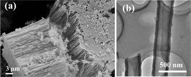 | ||
| Fig. 1 (a) SEM image of amorphous carbon nanotube brushes. (b) TEM image of individual amorphous carbon nanotubes. | ||
After the reaction of a-CNT brushes with the H3BO3–urea mixture, we obtain the nanotube structures shown in Fig. 2(a). These structures containing B, C and N replicate the brush-like morphology of the a-CNTs. The diameter of the BCN nanotubes is 170 nm and the lengths are 15 μm. The higher magnification FESEM image in Fig. 2(b) shows the open ends of the BCN nanotubes demonstrating the wall thickness to be around 50 nm. This is further supported by the TEM image of a single nanotube shown in Fig. 2(c). The selected area electron diffraction pattern shows faint rings, with a few spots. The XRD pattern of the BCN nanotube brushes [Fig. 3(a)] shows broad reflections with d spacings of 3.43 Å and 2.13 Å corresponding to (002) and (100) planes respectively, similar to the pattern reported for BC3N (JCPDS card 35-1292). The broad reflections in the XRD pattern and the diffuse rings in the electron diffraction pattern suggest the turbo static nature of the nanotubes as reported earlier for other preparations of BCN nanotubes.2 We have prepared a-CNTs using a polycarbonate membrane with a pore size of 50 nm. Using the a-CNTs, we have obtained BCN nanotube brushes. A FESEM image of these nanotube brushes so obtained is shown in the inset in Fig. 2(a). A TEM image of the BCN nanotubes with an outer diameter of 40 nm is shown in Fig. 2(d).
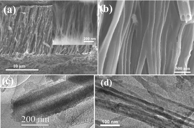 | ||
| Fig. 2 (a) FESEM images of BCN nanotube brushes with the average diameter of a single tube being around 170 nm. The inset shows a FESEM image of BCN nanotube brushes of 40 nm diameter. (b) Higher magnification FESEM images of BCN nanotube brushes. TEM image of a BCN nanotube (c) 170 nm diameter, (d) 40 nm diameter. | ||
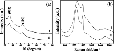 | ||
| Fig. 3 (a) XRD patterns and (b) Raman spectra of BCN nanotube brushes: (I) 40 nm diameter, (II) 170 nm diameter. | ||
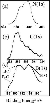
X-Ray photoelectron spectra of the BCN nanotubes in the N, C and B (1s) regions are shown in Fig. 4. We can analyze these data on the lines suggested by Kim et al.11 The N 1s spectrum of the BCN nanotube brushes in Fig. 4(a) shows peaks at 397.7 eV, 400.2 eV and 401.5 eV. The peak at 397.7 eV corresponds to nitrogen bonded to boron (N–B bond), the peak at 400.2 eV corresponds to nitrogen bonded to carbon in a graphite like N–C structure, and the peak at 401.5 eV can be assigned to N bonded to C in a pyridine type structure. The C 1s spectrum in Fig. 4(b) has two peaks with a broad shoulder, the peak at 284 eV is assigned to carbon bonded to a boron atom (C–B bond) and the peak at 286 eV is assigned to carbon bonded to another carbon atom (C–C bond). The long tapering band extending from 286 eV to 289 eV is ascribed to carbon atoms bonded to nitrogen. The B 1s spectrum in Fig. 4(c) has two peaks centered at 191.2 eV and 194 eV, with a shoulder at 189.2 eV. The shoulder at 189.2 eV corresponds to boron bonded to carbon (B–C bond), and the peak at 191.2 eV is due to boron bonded to nitrogen (B–N bond). The peak at 194 eV is assigned to boron bonded to oxygen (B–O bond), probably arising from the excess B2O3. B2O3 is, however, X-ray amorphous. By subtracting the contribution of the B–O part from the B 1s signal, we have estimated the composition of the nanotubes taking the capture cross sections into account. Such an analysis gave the approximate composition of the BCN nanotube brushes to be BC4N1.5.
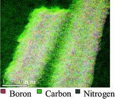
In order to obtain a more reliable elemental analysis, we carried out electron energy loss spectroscopy (EELS) measurements on the K-edge absorption for B, C, and N in a high-resolution electron microscope. The spectrum clearly showed K-shell ionization edges at 188, 284, and 401 eV for B, C and N respectively. Each core edge fine structure consisted of a sharp Π* peak and a well-resolved σ* band, characteristic of sp2 hybridization.13 The percentages of B and N were significantly smaller than that of carbon. EELS measurements gave an average chemical composition of the nanotubes to be BC4N. In Fig. 5 we show the elemental mapping of the nanotubes the red, green and blue colours representing boron, carbon and nitrogen respectively. We see that the colours are randomly distributed across the nanotubes suggesting that the nanotubes are homogeneous with a uniform distribution of B, C and N atoms. The homogeneous nature of the BC4N nanotubes is also confirmed by the fact that we failed to obtain BN nanostructures after removal of carbon from the BC4N nanotubes by oxidation.14
The Raman spectra of the BC4N nanotubes were recorded with the 633 nm line from a HeNe laser. The spectra are shown in Fig. 3(b). The observation of two strong peaks at 1324 cm−1 and at 1600 cm−1 in the Raman spectra are the signatures of the D and G bands of BCN nanotubes.15,16 The D bands are somewhat broad probably due to the disorder in the BCN layers. The additional peak at around 800 cm−1 is similar to that found in BN nanotubes. The band around 2600 cm−1 may be due to a combination D + G band or a 2D overtone. Such bands have been observed in BCN nanotubes of other compositions.15,16
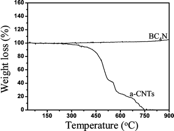
We have carried out thermogravimetric analysis of BC4N nanotubes in air. These nanotubes show high thermal stability and we observe no weight loss up to 900 °C (Fig. 6). Amorphous carbon nanotubes get completely oxidized before 750 °C. The high thermal stability of BC4N nanotubes is noteworthy.
In the literature, there have been theoretical papers describing magnetism of BCN nanotubes. BCN nanotubes having an approximate composition of BC2N have been predicted to be ferromagnetic.17 Such itinerant ferromagnetism has also been predicted in CBN heterostructured nanotubes.18BCN ribbons of the composition BC10N have been predicted to be ferrimagnetic.19Carbon doping in BN nanotubes is supposed to induce spontaneous magnetism.20 We have carried out magnetic susceptibility measurements of BC4N nanotube brushes and found them to be nonmagnetic. They show a very small magnetic moment (0.22 μB) probably due to defects on the nanotubes. The BC4N nanotubes are highly insulating, the resistivity being in the MΩ region.
Adsorption properties of materials are of importance in gas storage, selective gas recognition and separation. Zeolites and metal–organic frameworks have enjoyed high utility in gas adsorption because of the high surface areas, and well-defined pore shapes. We have measured the surface area of the as synthesized BC4N nanotube brushes using nitrogen adsoption–desorption isotherms at 77 K [Fig. 7(a)]. The surface area measured by the Brunauer–Emmett–Teller (BET) method was 356 m2 g−1 with contributions from micropores (0.7 nm) and mesopores (4 nm) as can be seen from the inset in Fig. 7(a). In Fig. 7(b), the CO2 adsorption on the BC4N nanotube brushes measured at low pressures and low temperature at 195 K are shown. The BC4N nanotube brushes showed remarkably high CO2 uptake of about 23.5 wt% at 195 K. The adsorption does not exhibit saturation even at P/P0 = 1, indicating the presence of unoccupied pores available for further uptake. The adsorption of hydrogen on the BC4N nanotubes was only 0.4 wt% at 77 K [Fig. 7(c)]. Thus, the BC4N nanotubes prepared by us are selective adsorbents of CO2. New materials having selective adsorption of CO2 are important for environment and industrial applications. Millward and Yaghi21 have studied CO2 adsorption by various metal–organic frameworks (MOFs), and reported the highest value of adsorption in the case of MOF-177 to be 33.5 mmol g−1, at ambient temperature and high pressures. Among the zeolites, the highest reported value of CO2 adsorption is 7.4 mmol g−1 for Zeolite 13X at high pressures and room temperature.22 Sudik et al.23 measured CO2 adsorption at 195 K and low pressures in certain iron carboxylate MOFs and reported that the highest CO2 uptake was for IRMOP-51 of 74 cm3 (STP) cm−3 (STP = standard temperature and pressure).
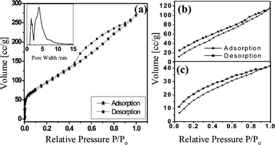 | ||
| Fig. 7 Adsorption–desorption isotherms of (a) N2 at 77 K (inset shows the pore size distribution), (b) CO2 at 195 K and (c) H2 at 77 K for BC4N nanotube brushes. | ||
In Fig. 8, we show the FESEM images of BC4N nanotubes decorated with Pt and Au nanoparticles. We see a uniform distribution of nearly monodisperse metal nanoparticles on the nanotube walls. The size of the metal nanoparticles is in the range 3–8 nm as found from the TEM images. Such metal nanoparticle decorated BC4N nanotubes could have useful applications.
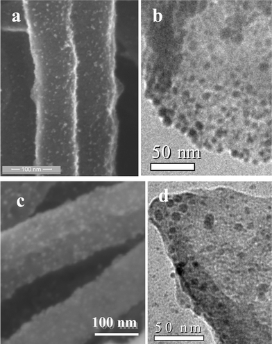 | ||
| Fig. 8 (a) FESEM image and (b) TEM image of Pt decorated BCN nanotubes. (c) FESEM image and (d) TEM image of Au decorated BCN nanotubes. | ||
The BC4N nanotubes can be formed in different ways. They could arise from the substitution of the BN layer in graphitic layers as proposed by earlier reports of BCN nanotubes.4 Kawaguchi2 described a BCN structure in terms of an infinite array of six-membered rings of carbon with ordered substitution of carbon atoms by boron and nitrogen. Zhang et al.6 reported BCN nanotubes with six inner layers of pure carbon and seven outer layers giving BC7N. The possibility of substitution of BN layers in graphitic layers is discarded, because the selective removal of graphitic layers from BC4N nanotubes by heating in the presence of oxygen was not possible.14 We shall now discuss the likely structure and properties of BC4N nanotubes based on first-principles calculations.
Let us consider benzene with substitution of BN in one of its C–C bonds. Every carbon atom contributes one π-electron to the nearest neighbor bonding in benzene, giving rise to a highly delocalized electron distribution over the entire ring with high resonance stabilization energy and strong C–H chemical shift (ring current). However, in a BN moiety, a complete one electron charge transfer between the B and N atoms gives rise to one π-electron in each of the B and N atoms, thereby causing charge equivalence with the C–C moiety. Thus, in BN substituted benzene (BC4N), the charge transfer between B and N causes charge localization thereby reducing the overall charge delocalization in the ring, in comparison with benzene. Within a quantum many-body model employing a Hubbard Hamiltonian with realistic parameters (ionization potential and electron affinity) for C, B and N, we find that the lowest molecular gap corresponds to a magnetic excitation (to a spin triplet state), which is 1.8 eV for benzene and 1.7 eV for BC4N. Charge excitation costs much more energy and the insulating gap in benzene (6.3 eV) reduces to 5.7 eV for BC4N due to the difference in ionization potentials and electron affinities of the constituent atoms.
Since consideration of BN substitution in a single benzene ring cannot capture the essence of the observed experimental findings in BN substituted carbon nanotubes, we will have to consider BN substitution in each of the benzene rings in both metallic and semiconducting carbon nanotubes. Boron nitride nanotubes (BNNTs) are always insulating unlike CNTs, which can be metallic or semiconducting depending on the chirality. BNNTs doped with a small amount of carbon can be made semiconducting with the appearance of dopant or defect states in the gap. As the concentration of carbon substitution at B and N sites is increased, one expects a crossover from an insulating to a metallic nature of electronic structure. In the present study, however, we are dealing with nanotubes having the well-defined composition, BC4N. We have carried out first-principles calculations on BC4N nanotubes with different (m,n) indices.
Our first-principles calculations are based on SIESTA24,25 implementation of density functional theory; such calculations have been very useful in determination of the electronic structure of single walled carbon nanotubes (SWNTs).26 We used Troullier–Martins soft pseudopotential27 with a local spin density approximation (Perdew–Zunger parametrization of the Ceperley–Alder functional) of the density functional theory as implemented in the SIESTA24,25 method. In these calculations, localized orbitals are used in the basis for representation of the Kohn–Sham28 wave functions, resulting in sparse representation of the Hamiltonian matrices and efficient diagonalization. We used a grid with an energy cutoff of 200 Ry in representation of the density. Structures were determined through minimization of energy until the Hellman–Feynman forces on the atoms were smaller in magnitude than 0.03 eV Å−1.
In order to examine various possible structural alternatives for BC4N, we have calculated properties of metallic CNTs with chirality of (6,6). Our calculations employed periodic boundary conditions with a hexagonal periodic unit cell: the size of this cell along the axis (z direction) of the tube is thrice the periodicity of the tube to accommodate different chemical ordering, and it is kept large enough in the perpendicular directions so that a vacuum of about 20 Å separates the periodic images of the tube ensuring minimal interaction among them. The dimension of the Brillouin zone (BZ) with such a choice of periodic cell is very small in the ab-plane and integrations over it were sampled with a 1 × 1 × 20 Monkhorst–Pack k-point mesh.29 We have used similar calculational parameters in studies of C-doped boron nitride nanotubes and B, N-doped carbon nanotubes.30
To facilitate comparison of energies of different structures, we used 72-atom supercell [(BN)12C48] in all calculations. We have considered four types of ordering of B and N atoms on the carbon sites of a (6,6) CNT (Fig. 9). In the first one, we have replaced one C–C bond with a B–N bond in each hexagonal ring. Since each of the six C–C bonds in a hexagonal ring is shared between two rings, this gives a correct concentration of atoms. There are many ways to distribute B–N bonds in this way; we have chosen the simple ordered structure S1 with alternate C–C bonds along the perimeter of CNT replaced with B–N bonds. In the second structure S2, we have substituted local structural units of BN3 and NB3 in a CNT, with no linkage between them [Fig. 9(c)]. In the structure S3, these local structural units (BN3 and NB3) link together with a B–N bond; i.e. S3 exhibits local structural units that are common to both S1 and S2 structures. Finally, we also considered a disordered structure D. Since no two boron or nitrogen atoms are expected to be neighbors, we started with BNNTs and substituted ⅙ of the boron and ⅙ of the nitrogen atoms with carbon using a pseudo-random number generator.
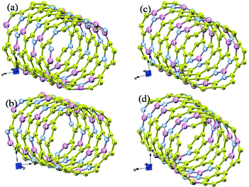 | ||
| Fig. 9 (6,6) BC4N nanotubes: (a) a disordered structure D, in which carbon atoms occupy B and N sites in a BNNT randomly with a probability of ⅔, (b) an ordered structure S1, with one B–N bond present in each carbon ring, (c) an ordered structure S2, where BN3 and NB3 units are distributed on alternate C6 rings, and (d) an ordered structure S3, in which BN3 and NB3 units are linked with one B–N bond. | ||
Relative energies (see Table 1) of these BC4N nanotubes clearly show that BN3 and NB3 local units are energetically more favorable (S2 is more stable than S1 by almost 130 meV per B–N bond) than the diatomic BN units. The S2 structure is further stabilized by almost 73 meV per atom through a B–N linkage between BN3 and NB3 local units to yield S3. The disordered configuration D, which consists of different types of local structural units (BN, BN3, NB3, BN2, etc), has a stability intermediate to S1 and S2 structures.
| Nanotube | Energy/eV atom−1 |
|---|---|
| D | 0.100 |
| S1 | 0.139 |
| S2 | 0.073 |
| S3 | 0.00 |
We now examine the electronic structure of the BC4N nanotubes through their density of states (see Fig. 10). For each of the four nanotubes, we find a nonmagnetic ground state in the optimized structure. For S1 and S2 BC4N nanotubes, we find features common to CNT and BNNTs: a weak density of states at the Fermi energy as in the (6,6) CNT26 and two strong peaks within one eV of the fermi energy as in a BNNT.30 In the disordered BC4N nanotube D, we find a pseudo-gap at the Fermi energy, which is common to many materials lacking long-range order. The S3 BC4N nanotube, however, exhibits a clear gap in its electronic structure of about 1 eV. We find two isolated bands in its band-structure (Fig. 11) that form the HOMO and LUMO electronic states and are interestingly symmetric with respect to the Fermi energy. From visualization of the HOMO and LUMO wave functions at Γ point, we find that the former is centered on the BN3 unit and the latter is centered on the NB3 unit, and they both have an overlap with orbitals of neighboring carbon atoms. The band gap opens up when the two units are linked with a B–N bond yielding a lower energy structure.
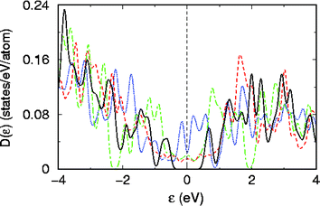 | ||
| Fig. 10 Density of electronic states of (6,6) BC4N nanotubes in the D (blue dotted lines), S1 (red dotted line), S2 (green dotted line) and S3 (solid black line) structures shown in Fig. 9. | ||
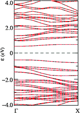 | ||
| Fig. 11 Electronic structure of a (6,6) BC4N nanotube of S3 type: bands corresponding to up and down spins are represented with black and red lines respectively (both are degenerate). | ||
Thus, the local structural units of BN3 and NB3 linked with B–N bonds (S3) would appear to be central to the stability of BC4N nanotubes, although chemically speaking S1 with alternate B–N bonds would appear more likely. We predict that a junction between a BNNT and a CNT should have good stability and interesting electronic properties. While the host CNT is metallic, we find that substitutional doping of B and N with large enough concentration (33%), shown here to be feasible experimentally, can make it insulating.
We have also carried out first-principles calculations on (6,0) and (8,0) nanotubes (Fig. 12) on a spin-polarized basis as mentioned above. However, in this case, we have used a cubic unit cell with twice the periodicity in the tube direction and a 1 × 1 × 60 Monkhorst–Pack k-point mesh integration. All other parameters remain the same as has been outlined above. In Fig. 13, we plot the density of states (DOS) for a (6,0) carbon nanotube and projected density of states (pDOS) for the corresponding BC4N nanotube with the same diameter and (m,n) indices. As can be seen, the (6,0) carbon nanotube is metallic as expected. Interestingly, the BC4N (6,0) nanotube also remains metallic. In fact, in the BC4N nanotube, the carbon density of states have larger contributions than the same from (6,0) carbon nanotubes at and close to the Fermi energy. The charge transfer induced states from B and N atoms also contribute to the DOS at the Fermi energy. We also find that the charge transfer between B and N affects the neighboring carbon atoms, allowing contributions from the out-of-plane π-orbitals density of carbon, close to the Fermi energy. However, the (6,0) nanotubes with the S3 structure where BN3 and NB3 units are linked show a semiconducting gap.
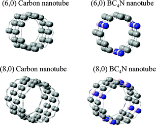 | ||
| Fig. 12 (6,0) and (8,0) carbon and BC4N nanotubes. | ||
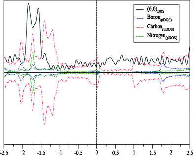 | ||
| Fig. 13 DOS of the (6,0) carbon nanotube and pDOS of the (6,0) BC4N nanotube. | ||
For the semiconducting (8,0) nanotube, the BN substitution in every hexagonal ring increases the semiconducting gap. For an (8,0) carbon nanotube, the semiconducting gap is 0.33 eV, while for the BC4N (8,0) nanotube, it increases to 0.40 eV. Both at the negative and positive energy regions near the Fermi energy, the carbon density of states is reduced compared to the (8,0) carbon nanotube, while very small but finite density of states from B and N appear at those energies, signifying charge transfer between B and N and with π-orbitals of neighboring C atoms (Fig. 14). These interesting features of metal–semiconductor transition and gap variation arise mainly from the heteroatom substitution leading to charge injection at the local sites with redistribution of charge densities over the entire system.
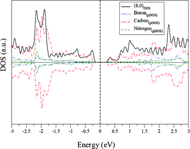 | ||
| Fig. 14 DOS of the (8,0) carbon nanotube and pDOS of the (8,0) BC4N nanotube. | ||
We have also carried out some initial calculations on BN substituted graphene nanoribbons with passivated edge atoms. We find that the edge atoms have finite magnetic moments, more so if the edge atoms are B and N. In fact, due to the finite magnetic moments at the edge sites, the delocalization of electrons over the neighboring sites induces some net spin even at the bulk atoms. This shows that if some B, N or C atoms occur at the edges with incomplete coordination, or a few B or N atoms occur as impurities in place of carbon, there is a possibility that the system would show a finite spin polarization, even at finite temperatures. Incorporation of BN in zig-zag graphene nanoribbons, however, makes it insulating.
Conclusions
It has been possible to synthesize nanotubes of the composition BC4N starting with a-CNTs prepared with the porous polycarbonate membranes. The reaction of the a-CNTs with a mixture of urea and boric acid provides an excellent means for the incorporation of boron and nitrogen in the carbon nanotubes. In the first step of the reaction, the decomposition of urea produces NH3, which on reaction with boric acid at high temperatures enables the incorporation of both boron and nitrogen in the carbon nanotubes. The BC4N nanotubes have been characterized by various physical methods and the composition established by EELS carried out in a high-resolution electron microscope. Although the nanotubes may not have an extended ordered structure with graphitic type BCN layers as there is sufficient order to give X-ray diffraction patterns and a well-defined Raman spectra. Surprisingly, BC4N nanotubes have very high thermal stability. They are nonmagnetic insulators with a high propensity for CO2 uptake (up to 23.5 wt%). First principle calculations indicate that the most stable structure may involve a graphitic network containing BN3 and NB3 units connected by a B–N bond. The other structure with a slightly higher energy is the one with ordered B–N bonds in all the six-membered rings. The latter structure is chemically more sensible. Calculations on (6,0), (6,6) and (8,0) BC4N naotubes show that they all are nonmagnetic and both (6,0) and (6,6) BC4N nanotubes open up a small semiconducting gap along with the (8,0) BC4N nanotube.Acknowledgements
One of the authors (KR) acknowledge CSIR (India) for the fellowship.References
- C. N. R. Rao and A. Govindaraj, Nanotubes and Nanowires, RSC Publishing, Cambridge, 2005 Search PubMed.
- M. Kawaguchi, Adv. Mater., 1997, 9, 8.
- O. Stephan, P. M. Ajayan, C. Colliex, P. Redlich, J. M. Lambert, P. Bernier and P. Lefin, Science, 1994, 266, 1683 CAS.
- K. Suenaga, C. Colliex, N. Demoncy, A. Loiseau, H. Pascard and F. Willaime, Science, 1997, 278, 653 CrossRef CAS.
- P. Redlich, J. Loeffler, P. M. Ajayan, J. Bill, F. Aldinger and M. Riihle, Chem. Phys. Lett., 1996, 260, 465 CrossRef CAS.
- Y. Zhang, H. Gu, K. Suenaga and S. lijirna, Chem. Phys. Lett., 1997, 279, 264 CrossRef CAS.
- R. Sen, B. C. Satishkumar, A. Govindaraj, K. R. Harikumar, G. Raina, J. P. Zhang, A. K. Cheetham and C. N. R. Rao, Chem. Phys. Lett., 1998, 287, 671 CrossRef CAS.
- (a) W. Q. Han, J. Cumings, X. Huang, K. Bradley and A. Zettl, Chem. Phys. Lett., 2001, 346, 368 CrossRef CAS; (b) M. Terrones, D. Golberg, N. Grobert, T. Seeser, M. Reyes-Reyes, M. Mayne, R. Kamalakaran, P. Dorozhkin, Z. C. Dong, H. Terrones, M. Ruhle and Y. Bando, Adv. Mater., 2003, 15, 1899 CrossRef CAS.
- M. Hubacek and T. Sato, J. Solid State Chem., 1995, 114, 258 CrossRef CAS.
- W. L. Wang, X. D. Bai, K. H. Liu, Z. Xu, D. Golberg, Y. Bando and E. G. Wang, J. Am. Chem. Soc., 2006, 128, 6530 CrossRef CAS.
- S. Y. Kim, J. Park, H. Chul Choi, J. P. Ahn, J. Q. Hou and H. S. Kang, J. Am. Chem. Soc., 2007, 129, 1705 CrossRef CAS.
- J. Dinesh, M. Eswaramoorthy and C. N. R. Rao, J. Phys. Chem. C, 2007, 111, 510 Search PubMed.
- X. D. Bai, C. Y. Zhi and E. G. Wang, J. Nanosci. Nanotechnol., 2001, 1, 35 CrossRef.
- W. Q. Han, W. Mickelson, J. Cumings and A. Zettl, Appl. Phys. Lett., 2002, 81, 1100.
- C. Y. Zhi, X. D. Bai and E. G. Wang, Appl. Phys. Lett., 2002, 80, 3590 CrossRef CAS.
- J. Wu, W. Q. Han, W. Walukiewicz, J. W. Ager, III and W. Shan, Nano Lett., 2004, 4, 647 CrossRef CAS.
- S. Okada and A. Oshiyama, Phys. Rev. Lett., 2001, 84, 146803 CrossRef.
- J. Choi, Y. H. Kim, K. J. Chang and D. Tomanek, Phys. Rev. Lett., 2003, 67, 146803.
- J. Nakamura, T. Nitta and A. Natori, Phys. Rev. Lett., 2005, 72, 205429.
- R. Q. Wu, L. Liu, G. W. Peng and Y. P. Feng, Appl. Phys. Lett., 2005, 86, 122510 CrossRef.
- A. R. Milliward and O. M. Yaghi, J. Am. Chem. Soc., 2005, 127, 17998 CrossRef CAS.
- S. Cavenati, C. A. Grande and A. E. Rodrigues, J. Chem. Eng. Data, 2004, 49, 1095 CrossRef CAS.
- A. C. Sudik, A. R. Millward, N. W. Ockwig, A. P. Cote, J. Kim and M. Yaghi, J. Am. Chem. Soc., 2005, 127, 7110 CrossRef CAS.
- P. Ordejon, E. Artacho and J. M. Soler, Phys. Rev. B, 1996, 53, R10441 CrossRef CAS.
- J. M. Soler, E. Artacho, J. D. Gale, A. Garcıa, J. Junquera, P. Ordejon and D. S. Anchez-Portal, J. Phys.: Condens. Matter, 2002, 14, 2745 CrossRef CAS.
- S. Reich, C. Thomsen and P. Ordejon, Phys. Rev. B, 2002, 65, 155411 CrossRef.
- N. Troullier and J. L. Martins, Phys. Rev. B, 1991, 43, 1993 CrossRef CAS.
- W. Kohn and L. J. Sham, Phys. Rev., 1965, 140, A1133 CrossRef.
- H. J. Monkhorst and J. D. Pack, Phys. Rev. B, 1976, 13, 5188 CrossRef.
- M. Upadhyay-Kahaly and U. V. Waghmare, J. Nanosci. Nanotechnol. Search PubMed , in press.
| This journal is © The Royal Society of Chemistry 2008 |

