Kinetic study of accelerated carbonation of municipal solid waste incinerator air pollution control residues for sequestration of flue gas CO2
Jia
Sun
,
Marta Fernández
Bertos
and
Stefaan J. R.
Simons
*
Centre for CO2 Technology, University College London, Torrington Place, London, UK WC1E 7JE. E-mail: stefaan.simons@ucl.ac.uk; Fax: +44 207 3832348; Tel: +44 207 6793805
First published on 6th August 2008
Abstract
It is known that accelerated carbonation technology can stabilise municipal solid waste incinerator air pollution control (APC) residues through encapsulation of hazardous components and cementation by carbonate precipitation. The aim of this work was to investigate the possibility of sequestering flue gas CO2 in APC residues with a view to reducing greenhouse gas emissions. The fundamental parameters affecting the carbonation process have been studied. An adverse effect of the CO2 concentration was observed and the optimum water-to-solid ratio and temperature were 0.3 and 20–30 °C, respectively. The reaction consisted of two stages. Initially, the reaction rate was controlled by the movement of the carbonation interface and the activation energy at this stage was 14.84 kJ mol−1; as the reaction proceeds, the rate controlling regime switched to gas diffusion through product layer control, and the activation energy was calculated to be 30.17 kJ mol−1. The openness of the pores in the solid is the key to carbonation efficiency. 10–12% (w/w) of CO2 can be trapped in APC residues during the carbonation process if flue gas is used.
Introduction
Global warming caused by the build-up of anthropogenic greenhouse gases in the atmosphere is already damaging the world's ecosystems. As one of the most significant of these greenhouse gases, carbon dioxide in the atmosphere has increased by 35% above pre-industrial levels since 1750.1,2 In respect to the targets set by the Kyoto Protocol, the UK government is committed to achieving a mandatory 60% cut in CO2 emissions compared to 1990 levels by 2050, with an intermediate target of between 26% and 32% by 2020.3 In order to achieve these emission reductions, the development of appropriate technologies and national emissions reduction policies will be required, including the development of economic methods to dispose of large volumes of CO2. One possibility is to capture and then store the CO2 in geological structures, saline aquifers and depleted oil/gas wells or in materials, where the CO2 is chemically stored in solid carbonates. The main advantages of this latter route are the formation of thermodynamically stable minerals and the subsequent safe and permanent sequestration of CO2.To achieve the aim of chemically storing CO2, low cost materials with high CO2 sequestration capacity are required. Municipal solid waste incinerator (MSWI) residues have been considered as an economic material with potential for CO2 sequestration due to their high content of calcium oxide and silica, suitable particle dimensions and the high volume produced every year.4 Municipal solid waste (MSW) is one of the major, growing, waste streams. Currently there are 30 Mt of MSW being produced per year in the UK, most of which is directly disposed of in landfill sites. However, in the face of decreasing UK landfill space, incineration has been considered as the best alternative for MSW disposal. Currently approximately 9% of MSW produced in England is incinerated which produces around 2.9 Mt MSWI residues per annum.5 The incineration of MSW results in two solid streams: bottom ash (BA), the ash residue after combustion; and air pollution control (APC) residues, collected from the flue gas cleaning process. APC residues are fine particles with large porosity, and rich in calcium oxide from the gas filters,4 which makes them more reactive to CO2 than BA.
Apart from the low cost, there are other advantages to using MSWI residues as a CO2 absorbent. Carbonation can stabilize MSWI residues by lowering their pH, reducing the leaching of heavy metals, as well as decreasing the matrix porosity.6 With more stable geochemical properties, the treated waste materials have the potential to be used as secondary aggregates.7 This would not only provide one solution to the problem of depleting natural aggregate resources, but would also divert significant amounts of material away from landfill.
In summary, the carbonation of MSWI residues represents a potential solution to sustainable waste management, the problem of decreasing landfill space, rising CO2 emission levels and the depletion of natural aggregate resources. To apply this technology into industry, an interesting idea is to use flue gas as the source of CO2. Indeed, Arickx et al.8 have studied the accelerated carbonation of BA utilising flue gas. At present, most research on carbonation of MSWI residues is focused on its influence on pH values and heavy metal leaching properties. Despite earlier work by the authors carried out under different reaction conditions to study the influence of these parameters,4,7 the reaction mechanisms and kinetics of accelerated carbonation are still not fully understood.
In this paper, the possibility of using flue-gas CO2 to carbonate APC residues is evaluated. The influences of the fundamental parameters affecting the carbonation process and the reaction mechanisms have also been studied.
Accelerated carbonation
Carbonation is a natural phenomenon affecting commonly used cement-based materials and can have harmful effects on structural concrete. On the other hand, carbonation has been demonstrated to have a beneficial impact on heavy metal-contaminated soils and other waste residues.9–12Accelerated carbonation is a controlled accelerated version of the naturally occurring process. In this patented process,13 hazardous wastes may be mixed with water and carbonated under a gaseous CO2 rich environment, to promote rapid solidification of the mixture within minutes. An increased binding of toxic metals occurs as the carbonated product rapidly solidifies.14 The consequent improvement in the chemical and physical properties of certain treated materials is significant (see Fernández Bertos et al. for a more detailed summary15), as it potentially allows them to be reused in a variety of construction applications. The major physical and chemical changes in MSWI ashes imparted by accelerated carbonation are:4,7
• The pH drops to nearly neutral
• The formation of calcium-metal salts and metal silicate complexes
• The CaCO3 precipitated in the pore space leads to a material of increased physical stability
• The leaching of major heavy metals, e.g. Pb, Zn and Cu, is markedly reduced
• The leaching of sulfate may be increased by carbonation, but may still be below the relevant landfill limits.
• The leaching of chlorides from BA remains unchanged, whilst it decreases for APC, though the final value is still over regulation limits.
The extent and quality of accelerated carbonation, and subsequent contaminant immobilisation, depend upon several parameters. The main ones are the reactivity and the diffusivity of CO2. The following is a scheme showing what these factors depend on:15

The carbonation of waste materials is a very complex reaction. Not only are there both physical and chemical processes occurring at the same time, but there are also many different factors dependent on the characteristics of the solid (i.e. the nature of the surface, the particle size, the microstructure, the composition and the mineralogy). All of these influence the reactivity of the waste. Diffusivity of CO2 is constrained by the pore system of the solid and the exposure conditions (i.e. concentration of CO2, degree of hydration, water-to-solid ratio and relative humidity).
The reaction between the solid and the CO2 takes place on the surface of the solid. This means that the reaction depends on the chemical adsorption of the CO2. Accelerated carbonation is based on the following sequential mechanism:16
1 Diffusion of CO2 in the gaseous layer surrounding the solid
2 Diffusion of CO2 through the solid
3 Solvation of CO2(g) to CO2(aq)
4 Hydration of CO2(aq) to H2CO3
5 Ionisation of H2CO3 to H+, HCO3−, CO32−
6 Dissolution of calcium containing phases
7 Nucleation of CaCO3
8 Precipitation of solid phases
Since these steps occur consecutively, if any one of them is slower than the others, the step becomes rate-determining. However, given the complexity of the waste materials, the reaction is likely to be influenced by more than one step.
When the APC residues are in contact with water, the alkali chlorides, together with some calcium, magnesium, zinc, lead and cadmium salts, at first rapidly dissolve.17 Since the concentration of calcium hydroxide is higher than the concentration of other hydration products, the reaction of CO2 with Ca(OH)2 predominates and the carbonation process can be simply described by the following overall reaction, which is the focus of this kinetic study:
| Ca(OH)2 + CO2 → CaCO3 +H2O | (1) |
This reaction represents only the final result of various steps through which the true reaction occurs. The second simplification is to consider reaction (1) irreversible and instantaneous, so that the calcium carbonate precipitates immediately once the two reactants are together. If the pores are filled with water, the low rate of CO2 diffusion in water hinders the reaction. However, if there is no water, the reaction does not occur. Thus, carbonation depends on the existence of the necessary conditions. As in most heterogeneous non-catalytic processes, the rate of reaction varies considerably depending on the conditions under which the experiment is performed.18
Materials and method
Air pollution control residues
The cleaning of gas from the incinerator before it is released into the air results in APC residues. APC residues are a mixture of fly ash, carbon and lime and are classified as hazardous waste due to the high pH, high concentration of heavy metals, chlorinated compounds and soluble salts. Moreover, APC ash consists of very fine particles, mostly <300 μm in diameter.Depending on the composition of the waste, type of incinerator and air pollution control process, the physical properties and chemical composition of APC residues differ from time to time. It has been reported that lime (CaO),7,19 portlandite (Ca(OH)2),4,7,20 calcium chloride hydroxide (Ca(OH)Cl)7 as well as other forms of calcium (e.g. ettringite, calcium-silicate-hydrate)21 and heavy metals are the components in APC residues that can be carbonated.
Generally speaking, due to the high amount of calcium hydroxide in APC residues, the carbonation of Ca(OH)2 was considered to be the main reaction that predominates the reaction mechanism of carbonation of APC residues.
The APC residues used in this study were provided by Onyx and were produced in the South East London Combined Heat and Power (SELCHP) incinerator in Lewisham (UK). The ashes, although freshly produced, were received damp and were oven dried at 105 °C to constant weight prior to investigation. They were characterised for their moisture content, bulk density, particle size distribution, mineral phases and morphology. The bulk density, the porosity, the tortuosity and the pore area were measured using a mercury porosimeter. Table 1 shows the physical properties of APC residues from the SELCHP incinerator.
| Moisture content (%) | 1.79 |
| Porosity (%) | 73.05 |
| Mean particle size/μm | 66.12 |
| Density/kg m−3 | 562.80 |
| Tortuosity | 6.20 |
| Total pore area/m2 g−1 | 4.39 |
Table 2 shows the composition of the APC residues as analysed by XRF. These data were provided by SELCHP.
| Oxide composition | Mass fraction (%) | Element | Content (ppm) |
|---|---|---|---|
| SiO2 | 30.00 | Zn | 7520.58 |
| Na2O | 7.81 | Pb | 3025.54 |
| Al2O3 | 12.12 | Br | 2061.60 |
| MgO | 2.5 | Cu | 534.36 |
| Fe2O3 | 1.05 | Sr | 473.98 |
| MnO | 0.04 | Ba | 319.46 |
| TiO2 | 0.53 | As | 210.66 |
| CaO | 36.27 | Zr | 111.34 |
| K2O | 2.03 | Ni | 70.32 |
| SO3 | 6.29 | Ce | 58.90 |
| W | 53.88 | ||
| La | 45.04 | ||
| Rb | 23.80 | ||
| Ga | 21.56 | ||
| Co | 14.16 | ||
| Th | 11.58 | ||
| Y | 4.86 | ||
| Nb | 2.16 | ||
| Mo | 0.94 | ||
| Bi | 0.86 | ||
| Se | 0.04 |
The main oxide components of the APC residues were: SiO2, CaO and Al2O3. In addition, the concentrations of magnesium, sodium and potassium compounds were rather high. The most abundant heavy metals were zinc and lead. The total amount of heavy metal represented approximately 2.2% of the total mass of the APC residues. The chemical composition of the ash used was similar to compositions given in the literature.17,22,23
Equipment and method
The carbonation rig used in this study is shown in Fig. 1. The static reactor was a 5 litre stainless steel chamber (1) with a cooling plate (2) inside. The cooling plate was connected to a temperature controller (3) which used water as a coolant. By adjusting the water temperature, the temperature in the reactor was controlled throughout the reaction. The outlet of the reactor (4) was connected to a vacuum pump (5) used to evacuate the residual air from the reactor prior to initial pressurisation. Two gas cylinders (6) were connected to the inlet of the reactor (7). Nitrogen and carbon dioxide were mixed in the reactor to achieve various carbon dioxide concentrations. | ||
| Fig. 1 Carbonation rig. | ||
The gas flow rates were controlled by rotameters (8). During the reaction process, the temperature of the reacting sample and pressure in the reactor were detected by a thermocouple (9) and a pressure gauge (10), respectively. A saturated solution of sodium chloride (11) was used to maintain the relative humidity at 75%. The sample holder (12) was made of stainless steel to improve the heat transfer between the solid and the cooling plate. It was perforated so that the temperature probe could measure, as closely as possible, the temperature of the reacting solid.
Prior to investigation, APC residues were dried at 105 °C in an oven for 24 h to constant weight. For all the experiments, 15 g of dry ash were mixed thoroughly with de-ionised water at selected water-to-solid ratios. The mixture was spread on the sample holder in a uniform 3 mm thick layer. The sample holder was then placed on the cooling plate in the reactor. The reactor was closed tightly and evacuated by the vacuum pump, then pressurised by nitrogen and carbon dioxide to achieve a 3 bar total pressure. APC residues were carbonated for 2.5 h. The pressure drop and the temperature were recorded throughout the reaction. The pressure drop indicated the CO2 being consumed by the carbonation reaction.
The reaction conditions used in the kinetic experiments are shown in three separate groups in Table 3. These experiments were designed to examine the fundamental parameters affecting the diffusivity and reactivity of CO2. The aim of Group 1 was to study the effect of CO2 concentration ([CO2]) and the possibility of utilising flue gas for the carbonation of APC residues. The selected water-to-solid ratio (w/s) and temperature (T) in Group 1 were the optimum values concluded from previous experimental work.4,7 In Groups 2 and 3, 20% [CO2] was used to simulate a typical flue-gas composition.
To examine the effect of the reaction in the APC residues, the mineralogy of fresh and fully carbonated APC residues were analysed by means of X-ray diffraction (XRD). The method of preparing the fully carbonated samples was slightly different from the procedure of the kinetic experiments described above. Ten grams of dry ashes were mixed with de-ionised water at 0.3 w/s and placed into the reactor containing 100% CO2 at 3 bar for 2 h. The ashes were then ground in a pestle and mortar and replaced in the reactor. This procedure was repeated five times to make sure the samples were fully carbonated.
Results and discussion
Changes in mineralogy
In order to confirm changes as a result of carbonation to the calcium compounds in APC residues, XRD analysis was performed, with Fig. 2 showing the results for fresh and fully carbonated APC residues. The residues have very noisy signals due to their heterogeneity and complex mineralogy. Aragonite was the preferred form of CaCO3 generated in the presence of chloride.24 However, the diffractogram shows that despite the high concentration of chloride in the form of NaCl and KCl in APC residues, vaterite was formed in preference to aragonite. Vaterite is known to be formed through a direct reaction of the carbonate ion in the presence of water vapour with the calcium ion in the solid.25 Although calcite is the most stable form of CaCO3, it seems that no calcite was formed during carbonation according to the unchanged intensity of the peaks corresponding to calcite. Fig. 2 also shows that after carbonation, the peaks representing portlandite (Ca(OH)2), lime (CaO) and calcium chloride hydroxide (CaClOH) disappeared. Apart from CaCO3, the carbonation of CaClOH also generates CaCl. However, peaks corresponding to CaCl cannot be observed in the diffractogram of the carbonated residue, since CaCl generated from carbonation reacts with KCl in the residue to form KCaCl3, which also explains the presence of KCaCl3 and the significant decrease of KCl after carbonation. | ||
| Fig. 2 XRD patterns of fresh and fully carbonated APC residues. | ||
Effect of CO2 concentration
The effect of gas phase CO2 concentration on the carbonation reaction can be seen in Fig. 3. The weight of CO2 consumed during the reaction can be calculated from eqn (2): | (2) |
 | ||
| Fig. 3 Evolution of reaction with time for different concentrations of CO2, w/s = 0.3, T = 20 °C. | ||
As can be seen from the plots in Fig. 3, the reaction rate was very fast during the first 20 min. However, after approximately 100 min, the reaction had effectively ceased.
These tests revealed that the concentration of CO2 has a converse effect on the carbonation of APC residues. Although the reaction rate at 20% CO2 was the slowest initially, it did not then decrease as fast as those at high CO2 concentration. The result of carbonation is the formation of calcium carbonate crystals. As the reaction proceeds, these crystals precipitate on the surface of the particles and block the pores, which prevents the internal diffusion of CO2. As a result, the reaction rate drops quickly and the reaction stops before all the mineral compounds are carbonated.26,27 When the concentration of CO2 is high, larger CaCO3 crystals form, which are more likely to block the pore area, making further reaction more difficult.20,28 Therefore, although accelerated carbonation reduces the carbonation time, higher CO2 concentrations do not mean better carbonation.
Within the range of these tests, the best carbonation result was achieved at 20% CO2 concentration. This is encouraging when considering carrying out carbonation using flue gases, in which the [CO2] is typically around this value.
Effect of water to solid ratio
The experiments showed that when w/s = 0.2, the initial rate of reaction is the highest. This was due to the easier diffusion of CO2 into the pores of the solid, as water was not blocking the pores. However, the final weight of CO2 absorbed when w/s = 0.2 was lower than that at w/s = 0.3 and 0.4, as shown in Fig. 4, due to the lower mobility of ions in the solid with reduced amounts of absorbed water. The lowest %W was observed at w/s 0.5. The highest %W was achieved at w/s 0.3.![Evolution of reaction with time at water to solid ratio from 0.2 to 0.5, [CO2] = 20%, T = 20 °C.](/image/article/2008/EE/b804165m/b804165m-f4.gif) | ||
| Fig. 4 Evolution of reaction with time at water to solid ratio from 0.2 to 0.5, [CO2] = 20%, T = 20 °C. | ||
The water content affects the reactivity of the system. Water is necessary for the carbonation reaction to precede as pore water hydrates and solvates the CO2 and dissolves the Ca2+ ions from the solid phase to react and form calcium carbonate. However, too much water hinders the diffusion of CO2 into the pores of the solid, since diffusion of CO2 in water is much slower than in air, approximately 104–105 times slower. Optimum water content depends on the pore structure of the material.29 It is considered here that materials with lower surface area have lower optimum water-to-solid ratio and vice versa.
Effect of temperature
The reaction of APC residues with 20% of CO2 was studied at temperatures of 10 °C, 20 °C, 30 °C, 40 °C and 80 °C. The experimental results are shown in Fig. 5 in terms of %Wvs. time t. It can be seen that the reaction rate increased as temperature increased.![Evolution of reaction with time at temperatures from 10 to 80 °C, [CO2] = 20%, w/s = 0.3.](/image/article/2008/EE/b804165m/b804165m-f5.gif) | ||
| Fig. 5 Evolution of reaction with time at temperatures from 10 to 80 °C, [CO2] = 20%, w/s = 0.3. | ||
The optimum reaction temperature was between 20 °C and 30 °C. Below 20 °C, the temperature was too low for the reaction to proceed. However, at temperatures above 30 °C, there is a decrease in the solubility of CO2 in water with increasing temperature. At 80 °C, the reaction stopped after 20 min, and %W was the lowest. Apart form the low solubility of CO2 in water, the loss of pore water in the solid at high temperature might be another reason. Hence, hot flue gas will have to be cooled to ambient temperature before it can be used to carbonate APC residues.
Kinetic analysis
The accelerated carbonation of APC residues is an irreversible gas/solid reaction. The reaction occurs initially at the outer layers of the particles and then the zone of reaction moves into the solid. At any time there is an unreacted core of material, which shrinks in size during the reaction. The rate controlling steps of a fluid–solid reaction are deduced by noting how the progressive conversion of the particles is influenced by the operating conditions.30To study the carbonation kinetics, α, the degree of transformation, is introduced in terms of a directly measurable parameter. The selected variable to monitor the extent of reaction is the partial pressure of CO2 (PCO2). Therefore, α has been defined as a function of this parameter as follows:
 | (3) |
In eqn (3), PCO20 and PCO2t are the partial pressure when reaction is started and stopped, respectively.
The carbonation kinetics of APC residues were studied through the comparison of measured values of α and t with the theoretical functions derived from eqn (4):31,32
| [1 − (1 − α)1/3]n = kt | (4) |
In eqn (4), k is the rate constant, and t is the time of carbonation; n is an index of the rate determining step. In the case of n = 1, eqn (4) represents a phase-boundary controlled reaction, which consists of rapid and dense nucleation, or initial rapid surface growth, followed by movement of a reaction front from all surfaces into the particles. When n = 2, eqn (4), known as the Jander equation, indicates a diffusion limited reaction and the rate controlling step is the diffusion through a product layer.
Eqn (5) is the logarithmic form of eqn (3). It can be seen that ln[1 − (1 − α)1/3] and ln t are in a linear relationship, and the slope of this line is 1/n.
| ln[1 − (1 − α)1/3] = (1/n)lnt + (1/n)lnk | (5) |
Fig. 6 shows the slopes of experimental curves of ln[1 − (1 − α)1/3]nvs. ln t for different concentrations of CO2. When the concentration of CO2 is 100%, the carbonation process is found to be diffusion through product-layer control. As the CO2 concentration decreases, the reaction shows signs of having two rate-controlling steps, phase-boundary control and diffusion through product-layer control. When [CO2] = 20%, this phenomenon is more obvious. At the start, the reaction is phase-boundary controlled. As the reaction proceeds, the controlling regime switches to the diffusion through product-layer control. According to Fick's Diffusion Law, the gas diffusion rate from gas to solid phase depends on the gradient of gas concentration. Therefore, at the phase-boundary controlled stage, high CO2 concentration in the surrounding atmosphere facilitates its diffusion through the water film to the solid surfaces. This also explains the phenomenon shown in Fig. 3, namely that in the first few minutes of reaction the reaction rate is faster at higher CO2 concentration. However, once the CO2 has diffused though the product layer into the unreacted core of the particle, the openness of the pores is more important to the gas diffusion rate than the concentration of CO2. Therefore, at the second stage of carbonation, the CO2 concentration has a converse effect on the reaction rate, since the higher the CO2 concentration, the faster the pores in the solid become blocked.
![Plot of ln[1 − (1 − α)1/3] vs. ln t at various concentrations of CO2 (average correlation coefficient R2 = 0.9843), w/s = 0.3, T = 20 °C.](/image/article/2008/EE/b804165m/b804165m-f6.gif) | ||
| Fig. 6 Plot of ln[1 − (1 − α)1/3] vs. ln t at various concentrations of CO2 (average correlation coefficient R2 = 0.9843), w/s = 0.3, T = 20 °C. | ||
Fig. 7 and Fig. 8 are the kinetic analyses of accelerated carbonation at various water-to-solid ratios and temperature, respectively. Since the concentration of CO2 selected for all these experiments was 20%, the reaction kinetics follow the same pattern, which is phase-boundary control followed by diffusion through product-layer control, except at 80 °C. At this temperature, the phase-boundary controlled reaction is the only step and the reaction is considered to come to an end before CO2 can diffuse through the product layer.
![Plot of ln[1 − (1 − α)1/3] vs. ln tat various water-to-solid ratios (average correlation coefficient R2 = 0.9874), [CO2] = 20%, T = 20 °C.](/image/article/2008/EE/b804165m/b804165m-f7.gif) | ||
| Fig. 7 Plot of ln[1 − (1 − α)1/3] vs. ln tat various water-to-solid ratios (average correlation coefficient R2 = 0.9874), [CO2] = 20%, T = 20 °C. | ||
![Plot of ln[1 − (1 − α)1/3] vs. ln tat various reaction temperatures (average correlation coefficient R2 = 0.9896), [CO2] = 20%, w/s = 0.3.](/image/article/2008/EE/b804165m/b804165m-f8.gif) | ||
| Fig. 8 Plot of ln[1 − (1 − α)1/3] vs. ln tat various reaction temperatures (average correlation coefficient R2 = 0.9896), [CO2] = 20%, w/s = 0.3. | ||
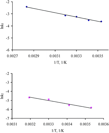
Experimental values of the reaction rate constants calculated from the experimental data shown in Fig. 8 are shown in Table 4; k1 and k2 are the rate constants for the surface-boundary controlled step and the diffusion through product-layer controlled step, respectively.
| T/°C | 10 | 20 | 30 | 40 | 80 |
| k 1/min−1 | 0.0262 | 0.0295 | 0.0394 | 0.0433 | 0.0894 |
| k 2/min−1 | 0.0030 | 0.0038 | 0.0075 | 0.0092 | ─ |
The relationship between k and temperature has been assumed to obey the Arrhenius equation, even though for solid reactions it is not always considered particularly reliable.33–35 However, this approach is the most widely accepted and, independent of the physical meaning of activation energy, is a well-established method of comparing kinetic data.
From the Arrhenius plot for the experimental data of ln(k) vs. 1/T (Fig. 9), the activation energies (Ea) have been determined from the slopes, which are Ea1 = 14.84 kJ mol−1 (R2 = 0.9894) for phase-boundary control, and Ea2 = 30.17 kJ mol−1 (R2 = 0.9568) for diffusion through product-layer control. The low value of Ea1 means that the reaction is dominated by surface diffusion along the grain boundaries. Although the value of Ea2 is higher, and falls above the maximum theoretical value for diffusion control, it is still lower than the usual values for chemical reaction control.36 A reaction controlled by only the rate of chemical reaction would have higher values of Ea due to its high sensitivity to temperature.37 Reactions in the solid state, such as carbonation, usually have a multi-step nature, which would imply the combination of two or more kinetic models. The results obtained in the kinetic analysis reported here suggest that the following carbonation mechanism for APC residues can be considered. When the APC residues contact with water, which contains carbonate ion and has a low pH (reactions (7) to (10)), the solid and the liquid phases are not in equilibrium. Calcium ions will dissolve into the liquid from the surface of the particles (reaction (6)). The carbonation reaction proceeds through the surface of the solid, then the calcium ions in the liquid are consumed to form calcium carbonate (reaction (11)) and precipitate on the solid surface.
| Ca (OH)2 → Ca2+ + OH− | (6) |
| CO2(g) → CO2 (aq) | (7) |
| CO2 (aq) + OH− → HCO3− | (8) |
| CO2 (aq) + H2O → H2CO3 | (9) |
| H2CO3 ↔ HCO3− + H+ ↔ CO32− + 2H+ | (10) |
| Ca2+ + CO32− → CaCO3 | (11) |
 | ||
| Fig. 9 (a) Arrhenius diagram for determining the activation energy of the diffusion through gas film control step (n = 1). (b) Arrhenius diagram for determining the activation energy of the diffusion through product-layer control step (n = 2). | ||
These reactions are very fast in bulk aqueous solution. However, the rate of these reactions may be reduced for a very thin absorbed water film.27Reaction (7) represents the adsorption and hydration of CO2. These two processes can occur at the surface of the water layer that covers both Ca(OH)2 and CaCO3, and are considered to be the slowest steps. The rate of the dissolution of Ca(OH)2 is faster than reaction (7), since the ash is thoroughly mixed with water prior to carbonation, thus the Ca2+ and OH− ions should already be present.
As carbonation progresses, the carbonate particles precipitate on the surface of the ash particles and build up a thicker product layer that increases the resistance to the penetration of CO2. Therefore, the diffusion through the product layer will become more significant at the final stages of reactions. In the present work, carbonation was observed to virtually cease after 2.5 h. However, it may well have continued over longer periods at a very slow rate by diffusion through the product layer.
Conclusions
The kinetic data of the accelerated carbonation reaction of APC residues at different CO2 concentrations, water-to-solid ratios and temperatures were obtained by measuring the consumption of CO2 with reaction time.The results show that, for accelerated carbonation of APC residues, the concentration of CO2 has a converse effect on the extent of carbonation. Within the range of the experiments reported here, the highest amount of CO2 was absorbed when the CO2 concentration was 20% (v/v). The results also suggest that water is an essential medium for the reaction and an optimum water-to-solid ratio exists. Too much or too little water will both hinder the reaction. To achieve better carbonation results, the reaction temperature has to be controlled around 20–30 °C.
According to the kinetic analysis, the carbonation of APC residues consists of two stages:
• In the first 5 to 10 min, the reaction rate is fast, and the nucleation on the phase boundary is the rate-controlling step. At this stage, the concentration of CO2 has a positive effect on the diffusion rate.
• As the reaction proceeds, the diffusion of CO2 through the product layer takes control. At this stage, the reaction rate is effectively ceased, and the gas diffusion rate depends mainly on the openness of the pores.
The experimental results indicate that the idea of sequestering flue-gas CO2 in MSWI APC residues via accelerated carbonation is not only feasible but is also very promising. 8–12% (w/w) of CO2 can be trapped in APC residues during the process. Meanwhile, the short reaction time will be beneficial to a large scale industrial treatment process. [Accelerated Carbonation is now being commercialised by Carbon 8 systems Ltd, www.c8s.co.uk].
References
- A. Neftel, H. Friedli, E. Moor, H. Lötscher, H. Oeschger, U. Siegenthaler, and B. Stauffer, Historical CO2 record from the Siple Station ice core, in Trends: A Compendium of Data on Global Change, Carbon Dioxide Information Analysis Center, Oak Ridge National Laboratory, U.S. Department of Energy, Oak Ridge, TN, USA, 1994 Search PubMed.
- C. D. Keeling and T. P. Whorf. Atmospheric CO2 records from sites in the SIO air sampling network, in Trends: A Compendium of Data on Global Change, Carbon Dioxide Information Analysis Center, Oak Ridge National Laboratory, U.S. Department of Energy, Oak Ridge, TN, USA, 2005 Search PubMed.
- DTI, Energy White Paper: Our energy future—creating a low carbon economy, The Stationery, Norwich, UK, 2003 Search PubMed.
- M. Fernández Bertos, X. Li, S. J. R. Simons, C. D. Hills and P. J. Carey, Green Chem., 2004, 6, 428–436 RSC.
- DEFRA, Incineration of Municipal Solid Waste, 2007, http://www.defra.gov.uk/environment/waste/wip/newtech/pdf/incineration.pdf Search PubMed.
- H. Zhang, P. J. He, L. M. Shao and D. J. Lee, Waste Manage., 2008, 28, 509–517 CrossRef CAS.
- X. Li, M. Fernández Bertos, C. D. Hills, P. J. Carey and S. Simons, Waste Manage., 2007, 27, 1200–1206 CrossRef CAS.
- S. Arickx, T. Van Gerven and C. Vandecasteele, J. Hazard. Mater., 2006, 137, 235–243 CrossRef CAS.
- S. Valls and E. Vàzquez, Cem. Concr. Res., 2001, 31, 1271–1276 CrossRef CAS.
- M. A. Venhuis and E. J. Reardon, Environ. Sci. Technol., 2001, 35, 4120–4125 CrossRef CAS.
- A. Macias, A. Kindness and F. P. Glasser, Cem. Concr. Res., 1997, 27, 215–225 CrossRef CAS.
- J. C. Walton, S. Bin-Shafique, R. W. Smith, N. Gutierrez and A. Tarquin, Environ. Sci. Technol., 1997, 31, 2345–2349 CrossRef CAS.
- C. D. Hills, US Pat., 5 997 629, 1999.
- L. C. Lange, Ph.D. Thesis, Queen Mary and Westfield College, 1997.
- M. Fernández Bertos, S. J. R. Simons, C. D. Hills and P. J. Carey, J. Hazard. Mater., 2004, 112, 193–205 CrossRef CAS.
- A. Maries, in Proceedings of Conference in Cement and Concrete Science, Oxford, 1985 Search PubMed.
- R. Derie, Waste Manage., 1996, 16, 711–716 CrossRef CAS.
- C. Y. Wen, Ind. Eng. Chem., 1968, 60(9), 34–54 CrossRef CAS.
- J. M. Chimenos, M. Segarra, M. A. Fernández and F. Espiell, J. Hazard. Mater., 1999, 64, 211–222 CrossRef CAS.
- R. Baciocchi, A. Polettini, R. Pomi, V. Prigiobbe, V. Zedtwitz-Nikulshyna and A. Steinfeld, in Proceedings of The First International Conference on Accelerated Carbonation for Environmental and Materials Engineering, London, 2006 Search PubMed.
- P. J. He, Q. K. Cao, L. M. Shao and D. J. Lee, Sci. Total Environ., 2006, 359, 26–37 CrossRef CAS.
- S. Rémond, P. Pimienta and D. P. Bentz, Cem. Concr. Res., 2002, 32, 303–311 CrossRef CAS.
- A. Polettini, R. Pomi, P. Sirini and F. Testa, J. Hazard. Mater., 2001, 88, 123–138 CrossRef CAS.
- S. Goñi and A. Guerrero, Cem. Concr. Res., 2003, 33, 21–26 CrossRef CAS.
- T. Nishikawa, K. Suzuki, S. Ito, K. Sato and T. Takebe, Cem. Concr. Res., 1992, 22, 6–14 CrossRef CAS.
- K. Van Balen, Cem. Concr. Res., 2005, 35, 647–657 CrossRef CAS.
- S. M. Shih, C. S. Ho, Y. S. Song and J. P. Lin, Ind. Eng. Chem. Res., 1999, 38, 1316–1322 CrossRef CAS.
- O. Cizer, K. Van Balen, D. Van Gemert and J. Elsen, in Proceedings of The First International Conference on Accelerated Carbonation for Environmental and Material Engineering, London, 2006 Search PubMed.
- K. Van Balen and D. Van Gemert, Mater. Struct., 1994, 27, 393–398 CrossRef CAS.
- O. Levenspiel, Chemical Reaction Engineering, John Wiley & Sons, New York, 3rd edn, 1999, ch. 25, pp. 566–588 Search PubMed.
- J. H. Sharp, G. W. Brindley and B. N. Narahari Acher, Am. Ceram. Soc. Bull., 1966, 49, 379–382 CAS.
- W. E. Brown, D. Dollimore and A. K. Galwey, in Comprehensive Chemical Kinetics, ed. C. H. Vamford and C. F. H. Tipper, Elsevier, Amsterdam, 1980, vol. 22, ch. 3, pp. 41–113 Search PubMed.
- J. D. Swery and M. E. Brown, Thermochim. Acta, 2002, 390, 217–225 CrossRef.
- A. K. Galwey and M. E. Brown, Thermochim. Acta, 2002, 386, 91–98 CrossRef CAS.
- A. K. Galwey and M. E. Brown, Thermochim. Acta, 1995, 269/270, 1–25 CrossRef.
- A. I. Fernández, J. M. Chimenos, M. Segarra, M. A. Fernández and F. Espiell, Hydrometallurgy, 1999, 53, 155–167 CrossRef CAS.
- M. J. Renedo and J. Fernández, Fuel, 2004, 83, 525–532 CrossRef CAS.
| This journal is © The Royal Society of Chemistry 2008 |