Solid-state fluorescence enhancement of organic dyes by photonic crystals
Yu-Qi Zhang, Jing-Xia Wang, Zhuo-Yu Ji, Wen-Ping Hu, Lei Jiang, Yan-Lin Song* and Dao-Ben Zhu*
Key Laboratory of Organic Solids, Institute of Chemistry, Chinese Academy of Sciences, Beijing, 100080, China. E-mail: ylsong@iccas.ac.cn; zhudb@iccas.ac.cn
First published on 23rd October 2006
Abstract
Photonic crystal (PC) films were fabricated by self-assembly of colloidal crystals using a vertical deposition method at invariant temperature and humidity. Organic dyes, whose emission wavelengths overlap the photonic stopbands of selected PCs, were deposited on the surface of PC films by thermal evaporation under vacuum. The fluorescence of organic dyes deposited on PCs is obviously enhanced in comparison with that on aluminium films and glass surfaces. There were 41-fold and 20-fold fluorescence enhancements when Rhodamine B base was deposited on the surface of a yellow PC film, compared with that on glass surface and aluminium film respectively, where PCs were utilized as a Bragg reflection mirror. The results show that the PCs are more effective and selective reflection mirrors than aluminium, and have potential applications in optoelectronic and lighting devices.
1. Introduction
Organic fluorescent dyes have attracted great attention due to their potential applications in optoelectronic and lighting devices.1–4 Presently, one focus is how to further improve the efficiency of these devices. One way for this aim is to increase the luminescence of molecular materials in the solid state. In fact, a metal-enhanced fluorescence (MEF) effect5,6 has been reported. For example, Lakowicz et al.5 observed a strong, more than 16-fold fluorescence enhancement when Texas Red-labeled BSA was deposited on a silver colloid coated surface. In addition, fluorescence resonance energy transfer (FRET),7,8 photoinduced fluorescence enhancement (PFE)9,10 and surface plasmon resonance (SPR) of metal nanoparticles11,12 have also been utilized to enhance fluorescence emission. Although the above-mentioned methods are effective for fluorescence enhancement, the involved experimental processes are usually complicated and the effect of such enhancement is limited. Here, we propose a simple, effective and practicable strategy to enhance fluorescence emission of molecular materials in the solid state. This method is crucially dependent on the reflection of a Bragg mirror of photonic crystals.Photonic crystals (PCs), firstly defined by Yablonovitch and John in 1987,13,14 have been paid much attention due to their unusual optical properties originating from the photonic stopband that affect the emission and propagation of light.15–20 PCs create new aspects for the fabrication of micro- and nanodevices as well as their integration with special optical properties. The promising applications of PCs have been demonstrated in many fields, such as light beam bending,21,22 spontaneous emission modification23–31 and light-emitting diodes.32,33 Especially, the stopband can inhibit light propagation in a certain direction for a given frequency, therefore, PCs can modify significantly the emission characteristics of embedded optically-active materials (dyes, polymers, semiconductors, etc.) as the emission wavelengths of the active materials overlap the stopband, which have been investigated extensively by many groups.23–31 Additionally, enhancement of photoluminescence by PCs has been reported by photonic defects34 and minimizing surface recombination losses of quantum dots at low temperature.35 Very recently, Klimov et al.36 have reported amplified spontaneous emission in semiconductor nanocrystals uniformly coated on opal polystyrene surfaces by enhancing the optical gain which was achieved by reducing the group velocity at the edge of the photonic stopband. However, solid-state fluorescence emission enhancement of organic dyes, employing PC surfaces as a Bragg mirror, has not been explored. We here report the drastic fluorescence surface emission enhancement of organic dyes deposited on PC surfaces compared with glass substrates and aluminium films.
2. Results and discussion
2.1. Morphology of PCs
We fabricated face-centered cubic (FCC) PCs films with various stopbands on glass substrates using a vertical deposition method37 with a suspension of poly(styrene–methyl methacrylate–acrylic acid) (P(St-MMA-AA)) spheres with different sizes synthesized by our group.38 Violet, cyan, green, yellow and red PC films were prepared using P(St-MMA-AA) latex spheres with diameters of 173, 204, 216, 244 and 280 nm, respectively. Fig. 1 shows the typical scanning electron microscopy (SEM) top-view images of the PC films mentioned above and a cross-sectional micrograph of the yellow PC film. These top-view images clearly indicate that the colloid spheres are in a FCC arrangement with the close-packed plane (111) oriented parallel to the substrates, with each sphere touching six others in one layer. The close-packed arrangement could extend over a large area (tens of square centimeters).38 Here the color indicates the positions of the stopbands of the corresponding PC films. The stopband positions of the violet, cyan, green, yellow and red PC films are at 460, 505, 530, 596, 644 nm, respectively, measured with a light incident along the normal surface of PCs. The cross-sectional SEM image shown in Fig. 1 suggests that the latex spheres are in contact with the neighboring underlayer.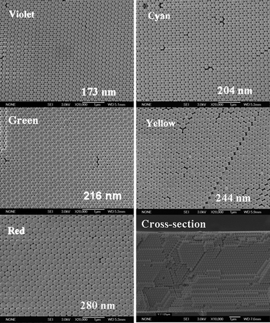 | ||
| Fig. 1 SEM top-view images of violet, cyan, green, yellow, and red PC films made of colloid spheres with average diameters of 173, 204, 216, 244 and 280 nm, respectively, and SEM image of a cross-section of a yellow PC film. | ||
2.2. The reflectivity of PC films
The optical properties of these PC films can be evaluated using UV-visible transmission and reflection spectra measured in normal incidence, which were reported in our previous work.38 Because the reflectivity of a photonic stopband is saturated above a certain critical thickness of the colloidal crystals,39 we have investigated the effect of thickness and reflectivities of PC films.Fig. 2a exhibits the reflectivities of yellow PC films with different thicknesses. The thickness of PC films was adjusted by changing the assembly concentration of the polymer latex suspension. From this graph, it can be seen clearly that the reflectivity of PC films increases with the thickness of PCs in the beginning and diminishes when the PCs are thicker than ca. 7 µm, which is probably owing to more defects in thicker PCs. The corresponding reflection spectra under different assembly concentrations are shown in Fig. 2b. This indicates that the center position of the photonic stopbands is at approximately 596 nm, which does not change obviously with assembly concentration, i.e., the thickness of the PC films. Therefore, the optimized thickness is about 7 µm, in which the PC film has the strongest reflectivity. The sample thicknesses were measured by cross-sectional SEM micrographs.
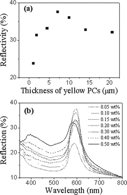 | ||
| Fig. 2 (a) The reflectivities of yellow PC films with different thicknesses. (b) The reflection spectra of yellow PC films with different assembly concentrations of (P(St-MMA-AA)) spheres. | ||
2.3. Fluorescence enhancement
According to the above results, we selected PC films of about 7 μm as Bragg mirrors. Organic dyes, including Rhodamine B base (RB), coumarin and tris(8-hydroxyquinoline)aluminium (AlQ3) were deposited on PC films by thermal evaporation under vacuum, in which the emission wavelengths of RB, coumarin and AlQ3 overlap the stopbands of matched PCs. Simultaneously, organic dyes were also deposited on glass and aluminium films as references. The aluminium films were obtained by depositing aluminium on glass substrates using vacuum thermal evaporation and the thickness was 35 nm.Fig. 3a shows a higher magnification SEM image of yellow PCs made of P(St-MMA-AA) colloid particles with an average diameter of 244 nm on a glass substrate. The image shows that the colloid particles have been arranged in a very orderly close-packed fashion. After RB was deposited on the PC film with a thickness of 20 nm under vacuum, the periodic structure of the PCs still remained perfect (Fig. 3b).
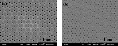 | ||
| Fig. 3 The higher magnification SEM images of yellow PCs (a) and a RB film with a thickness of 20 nm deposited on the PCs (b). | ||
The fluorescence spectra of RB with a thickness of 20 nm deposited on a yellow PC surface, an Al film and a glass substrate are given in Fig. 4a. Originally, glass surface was employed as a comparison.6 From Fig. 4a, it can be observed clearly that there is a remarkable fluorescence enhancement on the PC film, i.e., a 41-fold enhancement at the maximum wavelength of RB on PCs in comparison with that on glass surface. By considering the good reflection characteristics and practical applications of aluminium,40 we used Al film as another comparison. The results of Fig. 4a show that a 20-fold fluorescence enhancement on PCs in comparison with that on Al film has been obtained, which suggests that PC film is more effective than Al film as a reflection mirror. In theory, the fluorescence of organic dyes deposited on Al films should also be much stronger than that on glass surfaces according to the good reflection characteristics of Al. However, in fact, there is only about 2-fold enhancement obtained from Fig. 4a, which probably results from fluorescence quenching of organic molecules on the surface of the metal. In contrast, PC films will not quench the fluorescence of active materials, which makes them more advantageous than Al.
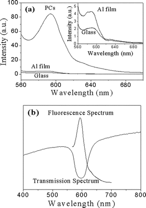 | ||
| Fig. 4 (a) The fluorescence spectra of 20 nm thick RB deposited on yellow PCs, aluminium film and glass substrate (λex = 550 nm). Here the fluorescence spectra were collected at the stopband direction of PCs. The inset shows the fluorescence spectra of RB (20 nm) on aluminium film and glass. (b) The transmission spectrum of yellow PCs and the fluorescence spectrum of RB deposited on the PCs. | ||
The fluorescence enhancement is attributed to the efficient reflection of the PC surface. As shown in Fig. 4b, the maximum emission peak (594 nm) of RB is exactly opposite to the transmission position (596 nm) of the yellow PC film, i.e., the emission wavelength of RB just overlaps the stopband of the yellow PCs. This indicates that the fluorescence will be reflected effectively since the PCs inhibit it from transmitting from the surface. Furthermore, the excitation light (λex = 550 nm) can also be reflected as the excitation wavelength is also in the range of the stopband (Fig. 4b). The excitation light reflected by a Bragg mirror can excite more dye molecules, which is also in favor of fluorescence enhancement.40
In fact, the fluorescence intensity is related to the radiation rates of light-emitting materials,41 electromagnetic field,42 and Bragg reflection. In this case, the Bragg reflection would be a main factor. Fig. 5 illustrates simply the fluorescence enhancement mechanism by reflection of PCs. Light with a wavelength which overlaps the stopband of PCs is suppressed by the PCs, i.e. there is no way for the emission to enter into the PCs. So the light will be reflected back in the direction of the stopband. However, light incident on glass without PCs will transmit to the substrate because of its low reflectivity. Fig. 5a shows that a light source emitted from the surface of PC film would be prohibited from transmitting through the surface and reflected back at the direction of the stopband and enhanced when its wavelength overlaps the stopband of the PCs. As for Al film, the fluorescence can be reflected to some extent because of its reflection characteristics. The fluorescence data (Fig. 4a) demonstrate that the PC surface is a more effective and selective reflection film than Al film. In contrast, as illustrated in Fig. 5b, the light would transmit and be lost if emitted from the glass surface. So the fluorescence of RB on glass is the weakest. In addition, Fig. 4b also shows that the reflection of PCs is selective (light whose wavelength overlaps the photonic stopband can be reflected), while that of Al is not.40 Therefore, PC film is more effective and selective than Al as a reflection mirror.
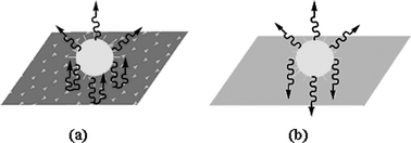 | ||
| Fig. 5 Schematic illustration of a light emitting source on the surface of a PC film (a) and a glass substrate without PCs (b). | ||
To confirm the above explanation, the same thickness of RB was deposited on different stopband PCs, and the relative fluorescence intensities are shown in Fig. 6a. The reflection spectra of different PCs are shown in Fig. 6b, which indicate the stopbands positions of those PCs. The results show that the strongest fluorescence occurs if both the excitation and emission wavelengths of RB (550 and 594 nm) are in the stopband range of yellow PCs. Similarly, the fluorescence intensities have also been increased on cyan and red PCs as the excitation or emission wavelengths are in the range of the stopbands of cyan or red PCs, respectively. In contrast, the RB film on the violet PCs has the weakest fluorescence because both the excitation and emission wavelengths are out of the stopband of violet PCs. Therefore, the PC surface acting as a Bragg mirror can increase the fluorescence intensity of organic dyes effectively because it enhances the excitation and/or emission light.
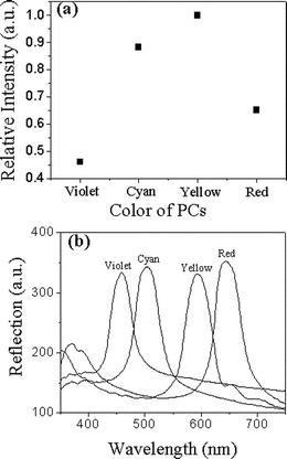 | ||
| Fig. 6 (a) The relative fluorescence intensities of the same thickness of RB deposited on violet, cyan, yellow and red PCs (λex = 550 nm, λem = 594 nm). (b) The reflection spectra of violet, cyan, yellow, and red PCs, showing their stopband positions at 460, 505, 596, 644 nm, respectively, measured with light incident along the normal surface of PCs. | ||
In addition, coumarin and AlQ3 have also been deposited on cyan and green PC films, with aluminium film also employed for comparison. Their fluorescence spectra are shown in Fig. 7. Obviously, the fluorescence of coumarin (Fig. 7a) and AlQ3 (Fig. 7b) are both enhanced drastically when they are deposited on the PC films. Numerically, there are about 14-fold and 9-fold enhancements at the maximum wavelengths of these two dyes on PCs compared with aluminium films. The emission wavelengths of coumarin and AlQ3 occur at 502 and 513 nm, which are both in the range of the corresponding stopbands of cyan and green PCs for which the center positions of the stopbands are at 505 and 530 nm, respectively. The fluorescence enhancement is related to the matchable degree of emission wavelengths and the stopbands of the photonic crystals, the reflectivity of the selected photonic crystals, the intrinsic properties of the organic dyes, and the quenching of aluminium. Thus the enhancements are different for RB, coumarin and AlQ3 on different PCs although the emission wavelengths overlap the photonic stopbands of the selected PCs. Therefore, the fluorescence on the PC films can also be reflected back and increased, which is based on the Bragg reflection mirrors of PC films.
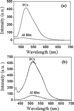 | ||
| Fig. 7 (a) The fluorescence spectra of 20 nm thick coumarin deposited on cyan PC film and aluminium film (λex = 432 nm). (b) The fluorescence spectra of 20 nm thick AlQ3 deposited on green PC film and aluminium film (λex = 400 nm). | ||
3. Experimental
3.1. Synthesis of (P(St-MMA-AA)) colloidal spheres38
(P(St-MMA-AA)) spheres were prepared via batch emulsion polymerization. Briefly, MMA (10.00 mmol), AA (13.89 mmol) and St (182.60 mmol) were dispersed in 100 mL water containing a minute dissolved amount of the emulsifier sodium dodecyl benzene sulfonate (SDBS, 0–0.011 mmol) and the buffer agent ammonium bicarbonate (6.30 mmol). The reaction mixture was kept at 70 °C for 0.5 h. Following the addition of an aqueous solution of ammonium peroxodisulfate (APS, 2.12 mmol), the polymerization was carried out at 80 °C for 10 h with continuously stirring. The resulting latex spheres were used directly without purification. The polydispersity of the latex spheres was about 0.005.3.2. Fabrication of PC films
The PC films were fabricated on glass substrates by a vertical deposition method.37 The glass slides were first treated with a chromic–sulfuric acid solution to ensure clean surfaces and were vertically positioned in a vial containing the monodisperse P(St-MMA-AA) aqueous suspension of ∼0.2 wt% at invariant temperature (50 °C) and humidity (60%) for 48 h. Yellow PC films with different thicknesses were fabricated by adjusting the concentration of the monodisperse aqueous suspension of colloidal crystals at the same temperature (50 °C) and humidity (60%).3.3. Characterization
The polydispersity of the latex spheres was detected by a ZetaPALS BI-90plus (Brookhaven Instruments). The SEM images were obtained with a field-emission scanning electron microscope (JEOL JSM-6700, Japan), after sputtering the samples with a thin layer of gold. Reflection spectra were recorded on a U-4100 UV-Visible spectrophotometer (Hitachi, Japan). Fluorescence spectra were measured by a F-4500 fluorescence spectrophotometer (Hitachi, Japan). The organic dyes were deposited onto PC films, glass and aluminium films under vacuum (∼6 × 10⁻⁴ Pa) at a rate of ∼0.2 A s−1 using a VPC-260 F Vacuum Deposition Equipment (ULVAC). The aluminium films on glass substrates with thickness of 35 nm were deposited under ∼4 × 10⁻⁴ Pa at rate of ∼1 A s−1.4. Conclusions
PC films were prepared successfully by self-assembly of colloidal crystals using a vertical deposition method. Solid-state fluorescence of organic dyes has been enhanced drastically by PCs as the excitation and/or emission wavelengths of the organic dyes are in the range of the photonic stopbands of the matched PCs, which demonstrates that the PCs will be more efficient and selective reflection mirrors than aluminium films. This method could be extended to other light-emitting materials and corresponding PCs. A promising application of the strategy could lead to a new generation of optoelectronic and lighting devices.Acknowledgements
We are grateful for the support of the National Natural Science Foundation of China (Grant Nos. 20574084 and 20421101) and the National Research Fund for 973 Program (No. 2006CB806200).References
- R. H. Friend, R. W. Gymer, A. B. Holmes, J. H. Burroughes, R. N. Marks, C. Taliani, D. D. C. Bradley, D. A. Dos Santos, J. L. Brédas, M. Lögdlund and W. R. Salaneck, Nature, 1999, 397, 121 CrossRef CAS.
- C. W. Tang and S. A. VanSlyke, Appl. Phys. Lett., 1987, 51, 913 CrossRef CAS.
- L. H. Chan, R. H. Lee, C. F. Hsieh, H. C. Yeh and C. T. Chen, J. Am. Chem. Soc., 2002, 124, 6469 CrossRef CAS.
- U. Mitschke and P. Bäuerle, J. Mater. Chem., 2000, 10, 1471 RSC.
- J. Lukomska, J. Malicka, I. Gryczynski and J. R. Lakowicz, J. Fluoresc., 2004, 14, 417 CrossRef CAS.
- J. R. Lakowicz, C. D. Geddes, I. Gryczynski, J. Malicka, Z. Gryczynski, K. Aslan, J. Lukomska, E. Matveeve, J. Zhang, R. Badugu and J. Huang, J. Fluoresc., 2004, 14, 425 CrossRef CAS; K. Aslan, J. R. Lakowicz and C. D. Geddes, J. Phys. Chem. B, 2005, 109, 6247 CrossRef CAS.
- P. Andrew and W. L. Barnes, Science, 2004, 306, 1002 CrossRef CAS.
- D. M. Willard, L. L. Carillo, J. Jung and A. V. Orden, Nano Lett., 2001, 1, 469 CrossRef CAS.
- S. Maenosono, Chem. Phys. Lett., 2003, 376, 666 CrossRef CAS.
- T. Uematsu, S. Maenosono and Y. Yamaguchi, J. Phys. Chem. B, 2005, 109, 8613 CrossRef CAS.
- T. Hayakama, K. Furuhashi and M. Nogami, J. Phys. Chem. B, 2004, 108, 11301 CrossRef.
- M. B. Mohamed, V. Volkov, S. Link and M. A. El-Sayed, Chem. Phys. Lett., 2000, 317, 517 CrossRef CAS.
- E. Yablonovitch, Phys. Rev. Lett., 1987, 58, 2059 CrossRef CAS.
- S. John, Phys. Rev. Lett., 1987, 58, 2486 CrossRef CAS.
- M. Fujita, S. Takahashi, Y. Tanaka, T. Asano and S. Noda, Science, 2005, 308, 1296 CrossRef CAS.
- S. Wong, V. Kitaev and G. A. Ozin, J. Am. Chem. Soc., 2003, 125, 15589 CrossRef CAS; S. H. Park, B. Gates and Y. Xia, Adv. Mater., 1999, 11, 462 CrossRef CAS.
- H. Míguez, S. M. Yang and G. A. Ozin, Langmuir, 2003, 19, 3479 CrossRef CAS; G. H. Springer and Da. A. Higgins, Chem. Mater., 2000, 12, 1372 CrossRef CAS.
- F. Fleischhaker, A. C. Arsenault, V. Kitaev, F. C. Peiris, G. von Freymann, I. Manners, R. Zentel and G. A. Ozin, J. Am. Chem. Soc., 2005, 127, 9318 CrossRef CAS.
- R. C. Schroden, M. Al-Daous, C. F. Blanford and A. Stein, Chem. Mater., 2002, 14, 3305 CrossRef CAS; V. N. Bogomolov, S. V. Gaponenko, I. N. Germanenko, A. M. Kapitonov, E. P. Petrov, N. V. Gaponenko, A. V. Prokofiev, A. N. Ponyavina, N. I. Silvanovich and S. M. Samoilovich, Phys. Rev. E, 1997, 55, 7619 CrossRef CAS.
- M. Egen and R. Zentel, Chem. Mater., 2002, 14, 2176 CrossRef CAS; S. G. Romanov, T. Maka, C. M. Sotomayor Torres, M. Müller and R. Zentel, Appl. Phys. Lett., 1999, 75, 1057 CrossRef CAS.
- A. Chutinan and S. Noda, Appl. Phys. Lett., 1999, 75, 3739 CrossRef CAS.
- S. Y. Lin, E. Chow, V. Hietala, P. R. Villeneuve and J. D. Joannopoulos, Science, 1998, 282, 274 CrossRef CAS.
- S. Fan, P. R. Villeneuve, J. D. Joannopoulos and E. F. Schubert, Phys. Rev. Lett., 1997, 78, 3294 CrossRef.
- E. P. Petrov, V. N. Bogomolov, I. I. Kalosha and S. V. Gaponenko, Phys. Rev. Lett., 1998, 81, 77 CrossRef CAS.
- S. V. Gaponenko, V. N. Bogomolov, E. P. Petrov, A. M. Kapitonov, D. A. Yarotsky, I. I. Kalosha, A. A. Eychmueller, A. L. Rogach, J. McGilp, U. Woggon and F. Gindele, J. Lightwave Technol., 1999, 17, 2128 CrossRef CAS.
- S. V. Gaponenko, V. N. Bogomolovb, E. P. Petrova, A. M. Kapitonova, A. A. Eychmuellerd, A. L. Rogachd, I. I. Kaloshaa, F. Gindelee and U. Woggon, J. Lumin., 2000, 87–89, 152 CrossRef CAS.
- L. Bechger, P. Lodahl and W. L. Vos, J. Phys. Chem. B, 2005, 109, 9980 CrossRef CAS; M. Megens, J. E. G. J. Wijnhoven, A. Lagendijk and W. L. Vos, J. Opt. Soc. Am. B, 1999, 16, 1403 Search PubMed.
- P. Lodahl, A. F. van Driel, I. S. Nikolaev, A. Irman, X. Overgaag, D. Vanmaekelbergh and W. L. Vos, Nature, 2004, 430, 654 CrossRef CAS; A. F. Koenderink and W. L. Vos, Phys. Rev. Lett., 2003, 91, 213902 CrossRef.
- R. C. Schroden, M. Al-Daous and A. Stein, Chem. Mater., 2001, 13, 2945 CrossRef CAS.
- F. Fleischhaker and R. Zentel, Chem. Mater., 2005, 17, 1346 CrossRef CAS.
- M. Müller, R. Zentel, T. Maka, S. G. Romanov and C. M. Sotomayor Torres, Chem. Mater., 2000, 12, 2508 CrossRef.
- M. Boroditsky, T. F. Krauss, R. Coccioli, R. Vrijen, R. Bhat and E. Yablonovitch, Appl. Phys. Lett., 1999, 75, 1036 CrossRef CAS.
- Y. R. Do, Y. C. Kim, Y. W. Song, C. Cho, H. Jeon, Y. J. Lee, S. H. Kim and Y. H. Lee, Adv. Mater., 2003, 15, 1214 CrossRef CAS.
- J. Y. Ye, M. Ishikawa, Y. Yamane, N. Tsurumachi and H. Nakatsuka, Appl. Phys. Lett., 1999, 75, 3605 CrossRef CAS.
- H. Y. Ryu, Y. H. Lee, R. L. Sellin and D. Bimberg, Appl. Phys. Lett., 2001, 79, 3573 CrossRef CAS.
- G. R. Maskaly, M. A. Petruska, J. Nanda, I. V. Bezel, R. D. Schaller, H. Htoon, J. M. Pietryga and V. I. Klimov, Adv. Mater., 2006, 18, 343 CrossRef CAS.
- P. Jiang, J. F. Bertone, K. S. Hwang and V. L. Colvin, Chem. Mater., 1999, 11, 2132 CrossRef CAS.
- J. X. Wang, Y. Q. Wen, H. L. Ge, Z. W. Sun, Y. M. Zheng, Y. L. Song and L. Jiang, Macromol. Chem. Phys., 2006, 207, 596 CrossRef CAS.
- C. Hong, I. Drikis, S. Y. Yang, H. E. Horng and H. C. Yang, J. Appl. Phys., 2003, 94, 2188 CrossRef CAS.
- A. J. M. Vermorken, C. M. A. A. Goos and M. W. A. C. Hukkelhoven, Anal. Chem., 1983, 55, 2464 CrossRef CAS.
- V. Lousse and J. P. Vigneron, Phys. Rev. B, 2001, 64, 201104 CrossRef.
- R. Wang, X. H. Wang, B. Y. Gu and G. Z. Yang, Phys. Rev. B, 2003, 67, 155114 CrossRef.
| This journal is © The Royal Society of Chemistry 2007 |
