Green synthesis of titania nanowire composites on natural cellulose fibers†
Natarajan Sathiyamoorthy
Venkataramanan
,
Keitaro
Matsui
,
Hajime
Kawanami
and
Yutaka
Ikushima
*
Research Center for Compact Chemical Process, National Institute of Advanced Industrial Science and Technology (AIST), 4-2-1, Nigatake, Miyagino-ku, Sendai, 983-8551, Japan. E-mail: y-ikushima@aist.go.jp; Fax: +81-22-232-7002; Tel: +81-22-237-521
First published on 13th October 2006
Abstract
A simple, efficient and environmentally benign approach for the synthesis of titania nanowire is achieved by using natural fibres as templates and ionic liquids as solvent.
Since the discovery of carbon nanotubes, nanotubular materials have received great attention, both on their fundamental and industrial aspects, due to their superior properties and applications.1 Unfortunately, reports on their synthesis, especially of metal oxides, by environmentally benign approaches are scarce,2,3 as they are extremely unstable and need organic supports. Among the various metal oxides, titania has attracted much attention, owing to its utility in the photochemical splitting of water,3 as an electrode material in dye-sensitized solar cells,4 as a photocatalyst for removal of harmful organic compounds,5 in UV-protective and self-cleaning coatings6 and as a catalyst support.7 Recently, much interest has been paid to the shape-controlled synthesis of anisotropic titania nanorods or nanowires.8 These nanowires are found to play an important role as both interconnections and active components in fabricating nanoscale electronic, photonic devices and as sensors.9
Templating is commonly employed for the controlled production of materials with an ordered structure and with desired properties. In the past, a variety of templates, including aluminium oxide,10 carbon nanotubes,11 surfactants,12 polymer fibers,13 supramolecular compounds14 and egg shell membranes15, has been widely used. Recently, Kunitake et al. have used natural cellulosic substances as templates for the synthesis of titania nanotubes with varying outer diameter, as a replica of the initial cellulose fibers, by a repeated filtration–deposition cycle using a nanocoating technique.16
Synthesis of nanomaterials in solvents has the advantage of uniform coating of the materials on the surface of the template. In this context ionic liquids (ILs) are considered to be a green solvent for the synthesis of organic substances. Only in recent years, due to the environmental knowledge, has attention been focused on the synthesis of nanomaterials by the use of ionic liquids as solvents.17 Hollow TiO2 microspheres have been prepared in hydrophobic ionic liquids, and it was reported that the size was influenced by the counter ion, the rate of stirring and the reaction temperature.18 Rogers et al. have shown that ILs can be used as non-derivatizing solvents for cellulose, and regeneration of the cellulose fibers can be achieved by the addition of water or ethanol solution without a change in its morphology.19 It is important to note that natural cellulose fibers possess surface hydroxyl groups, and can be a suitable binder for immobilization and stabilization of metal oxide nanoparticles.20 In continuation of the environmentally benign methods for the synthesis of nanoparticles,3 herein we report a green and simple method for the synthesis of TiO2 nanowires on cellulose fibre by taking advantage of the dissolution of cellulose in an ionic liquid, and thereby obtaining a uniform TiO2 layer over cellulose.
The TiO2/cellulose composite wires were prepared by the addition of Ti(OBu)4 (0.5 mg) over a period of 30 min to a dissolved lint free cellulose sheet (0.5 mg) (Adventec, Japan) in 5 ml of 1-butyl-3-methylimidazolium chloride ([C4mim]Cl). To this stirred solution, 20 ml of ethanol was added, and centrifuged to remove the IL and the unreacted metal alkoxide. Complete removal of IL was done by washing the TiO2 composite for several times. Finally, the material was dried in flowing air at ambient temperature.
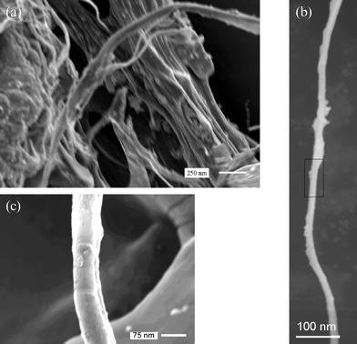
The field emission scanning electron microscopy (FESEM)‡ image in Fig. 1(a) shows a network of TiO2 layered fibers with the morphology of the cellulose template and their replica. Fig. 1(b) shows the individual TiO2/cellulose composite nanowires, separated from the assembly, which is 100–500 nm in length. It is important to note that the cellulose sheet used in the present study is composed of long uniform cellulose fibers in a network morphology, and the regenerated cellulose fibers will have a uniformity from the interior to the exterior surface.21Fig. 1(c) shows the uniform TiO2 layer, with wall thickness of 30–100 nm. However these nanowires were found to be fragile. The thickness of the TiO2 layer can be controlled by changing the concentration of the Ti(tOBu)4.
 | ||
| Fig. 1 FESEM image of TiO2/cellulose composite wire. (a) Titania replicas of cellulose, (b) individual nanowires separated from the assembly, (c) FESEM image of the boxed area in (b). | ||
As expected, the energy dispersive X-ray (EDX)‡ analysis of TiO2/cellulose composite shows that the composition present is C, O and Ti. The X-ray diffraction analysis‡ of TiO2/cellulose composite showed no peaks, indicating that the composite is amorphous. On the other hand, calcined TiO2 (500 °C, 2 h) displayed crystalline reflection peaks that are characteristic to the anatase TiO2.
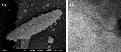
Fig. 2(a) shows the FESEM image of the calcined nanowires, retaining the morphology of the cellulose sheet, but with a porous crystalline formation due to the higher temperature of calcination. A typical HRTEM‡ image of the titania nanowires obtained from the calcined TiO2/cellulose composite at 500 °C for 2 hours is shown in Fig. 2(b). The image revealed the presence of many crystallites showing clear anatase lattice fringes. The nanotubes consist of anatase nanocrystals, which was further confirmed from the XRD pattern.
 | ||
| Fig. 2 (a) FESEM image of the calcined TiO2/cellulose composite, (b) HRTEM image of calcined TiO2 nanowires constituting networks of the cellulose template. | ||
The specific surface area was measured by physisorption of nitrogen according to Brunauer–Emmett–Teller (BET), and for the nanotubes obtained after calcination was found to be 14.65 m2 g−1, higher than observed by Su et al. for anatase nanoparticles calcined at 700 °C.22 Reflectance UV–Vis spectroscopic data of the calcined TiO2 wire shows an absorption edge of 360 nm that corresponds to a size of 3.0 nm for the anatase nanoparticles, which was in agreement with the previous reports.23
In conclusion, we demonstrate herein an efficient and green chemical pathway to TiO2/cellulose nanowire composites and titania nanotubes by the surface sol-gel process, using an IL as a green solvent medium and cellulosic substances as templates. This method is advantageous as it gives a uniform surface of TiO2 around the template and the IL can be reused. This approach may provide a pathway to synthesis of hybrid metal–titania nanotubes and metal nanowires, which is under investigation.
Notes and references
- (a) M. Law, J. Goldberger and P. Yang, Annu. Rev. Mater. Res, 2004, 34, 83 CrossRef CAS; (b) J. Goldberger, R. Fan and P. Yang, Acc. Chem. Res., 2006, 39, 231 CrossRef.
- (a) Q. Lu, F. Gao and S. Komarneni, Langmuir, 2005, 21, 6002 CrossRef CAS; (b) Q. Y. Lu, F. Gao and S. Komarneni, Adv. Mater., 2004, 16, 1629 CrossRef CAS; (c) P. Raveendran, J. Fu and S. L. Wallen, J. Am. Chem. Soc., 2003, 125, 13940 CrossRef CAS; (d) J. C. Liu, P. Raveendaran, Z. Shervani and Y. Ikushima, Chem. Commun., 2004, 2582 RSC; (e) J. Liu, G. Qin, P. Raveendran and Y. Ikushima, Chem.–Eur. J., 2006, 12, 2131 CrossRef CAS.
- J. H. Park, S. Kim and A. J. Bard, Nano Lett., 2006, 6, 24 CrossRef CAS.
- U. Bach, D. Lupo, P. Comte, J. E. Moser, F. Weisso, J. Salbeck, H. Spreitzer and M. Graetzel, Nature, 1998, 395, 583 CrossRef.
- A. Fujishima, T. N. Rao and D. A. Tryk, J. Photochem. Photobiol., 2000, 1, 1 Search PubMed.
- (a) S. Baskaran, L. Song, J. Liu, Y. L. Chen and G. L. Graff, J. Am. Ceram. Soc., 1998, 81, 401 CAS; (b) G. Dagan and M. Tomkiewics, J. Phys. Chem., 1993, 97, 12651 CrossRef CAS.
- S. Matsuda and A. Kato, Appl. Catal., 1983, 8, 149 CrossRef CAS.
- (a) X. Jiang, Y. Wang, T. Herricksb and Y. Xia, J. Mater. Chem., 2004, 14, 695 RSC; (b) J. M. Wu, W. T. Wu and H. C. Shih, J. Electrochem. Soc., 2005, 152, G613–G616 CrossRef CAS; (c) Y. Xiong, B. T. Mayers and Y. Xia, Chem. Commun., 2005, 5013 RSC.
- Y. Huang, X. F. Duan and C. M. Lieber, Small, 2005, 1, 142 CrossRef CAS.
- Z. Miao, D. Xu, J. Ouyang, G. Guo, X. Zhao and Y. Tang, Nano Lett., 2002, 2, 717 CrossRef CAS.
- D. Eder, I. A. Kinloch and A. H. Windle, Chem. Commun., 2006, 1448 RSC.
- M. Adachi, Y. Murata, J. Takao, J. Jiu, M. Sakamoto and F. Wang, J. Am. Chem. Soc., 2004, 126, 14943 CrossRef CAS.
- L. Zhang and M. Wan, J. Phys. Chem. B, 2003, 107, 6748 CrossRef CAS.
- M. N. Tahir, M. Eberhardt, P. Theato, S. Faiβ, A. Janshoff, T. Gorelik, U. Kolb and A. Tremel, Angew. Chem., Int. Ed., 2006, 45, 908 CrossRef CAS.
- D. Yang, L. M. Qi and J. M. Ma, J. Mater. Chem., 2003, 13, 1119 RSC.
- (a) I. Huang, I. Ichinose and T. Kunitake, Angew. Chem., Int. Ed., 2006, 45, 2883 CrossRef; (b) J. Huang and T. Kunitake, J. Am. Chem. Soc., 2003, 125, 11834 CrossRef CAS.
- (a) E. R. Cooper, C. D. Andrews, P. S. Wheatley, P. B. Webb, P. Wormald and R. E. Morris, Nature, 2004, 430, 1012 CrossRef CAS; (b) D. S. Jacob, A. Joseph, S. P. Mallenahalli, S. Shanmugam, S. Makhluf, J. Calderon-Moreno, Y. Koltypin and A. Gedanken, Angew. Chem., Int. Ed., 2005, 44, 6560 CrossRef CAS.
- T. Nakashima and N. Kimizuka, J. Am. Chem. Soc., 2003, 125, 6386 CrossRef CAS.
- (a) R. P. Swatloski, S. K. Spear, J. D. Holbrey and R. D. Rogers, J. Am. Chem. Soc., 2002, 124, 4974 CrossRef CAS; (b) M. B. Turner, S. K. Spear, J. D. Holbrey and R. D. Rogers, Biomacromolecules, 2004, 5, 1379 CrossRef CAS; (c) R. C. Remsing, R. P. Swatloski, R. D. Rogers and G. Moyna, Chem. Commun., 2006, 1271 RSC.
- H. Zhang, J. Wu, J. Zhang and J. He, Macromolecules, 2005, 38, 8272 CrossRef CAS.
- J. H. He, T. Kunitake and T. Watanabe, Chem. Commun., 2005, 795 RSC.
- C. Su, B. Y. Hong and C. M. Tseng, Catal. Today, 2004, 96, 119 CrossRef CAS.
- A. Furube, T. Asahi, H. Masuhara, H. Yamashita and M. Anpo, J. Phys. Chem. B, 1999, 103, 3120 CrossRef CAS.
Footnotes |
| † Electronic supplementary information (ESI) available: A detailed experimental procedure, reflectance spectra, XRD and EDX spectra. See DOI: 10.1039/b609887h |
| ‡ FESEM images were recorded on a JEOL JSM-6330FS Fluorescent Emission Scanning Electron Microscope, along with energy dispersion X-ray (EDX) analysis. X-Ray powder diffraction (XRD) patterns were recorded on a Japan Rigaku D/max-c rotation anode X-ray diffractometer, using CuKα radiation (l ≈ 1.54178 Å), with a scanning rate of 2° s−1. HRTEM images were recorded on a Hitachi H-800 TEM at an operating voltage of 200 kV. |
| This journal is © The Royal Society of Chemistry 2007 |
