A near real-time system for continuously monitoring airborne subtilisin-type enzymes in the industrial atmosphere
Frederick J.
Rowell
*a,
David
Sykes
b,
Lynsey
Grieveson
a,
Brenden
Theaker
a,
Latha
Sundar
a and
Robert H.
Cumming†
b
aNorth East Biotechnology Centre, School of Health, Natural and Social Sciences, University of Sunderland, Sunderland, UK SR1 3SD. E-mail: frederick.rowell@sunderland.ac.uk; Fax: +44 191 5152502; Tel: +44 191 5152563
bNorth East Biotechnology Centre, School of Science and Technology, University of Teesside, Middlesbrough, UK TS1 3BA
First published on 1st December 2006
Abstract
We describe the development and validation of a portable system comprising an air sampler coupled to an automated flow injection analysis device. The system is able to monitor airborne concentrations of subtilisin-type enzymes in the workplace atmosphere on a continuous basis. Sampling is in two stages: using a sampling head that is designed to mimic human respiration at approx. 1 m s−1 at a sampling rate of 600 l min−1. In the second stage, the captured particles are deposited by impaction from the air stream onto the inner surface of a cyclone that is continuously washed with a jet of buffer solution. Deposited particles are then washed into a reservoir from which samples are taken every 5–6 min and injected automatically into a continuous flow injection analysis system. Proteolytic enzyme in the sample passes through a bioreactor maintained at about 40 °C. This contains a cellulose solid phase matrix on which is covalently immobilised Texas Red-labelled gelatin as substrate. The passing enzyme partially digests the substrate releasing fluorophore that is detected down stream in a flow cell coupled to a fluorimeter. The system is calibrated using enzyme standards and the intensity of the resulting peaks from the ex-air samples is converted to airborne concentrations using a mathematical model programmed into a PC. The system has a limit of detection of 4.8 ng m−3 and a dynamic range of 5–60 ng m−3. The within assay precision (RSD) is 6.3–9.6% over this range. The within batch precision is 20.3% at 20 ng m−3 and the corresponding between batch value is 19.5%. The system has been run for periods up to 8 h in the laboratory and for up to 4 h at a factory site and the values obtained compared with time-averaged values obtained from a conventional Galley sampler and in-house analysis when reasonable agreement of the results was observed. The stability of the system over 21 days of continuous use with standards injected periodically was studied. Linearity was observed for all the standard plots throughout. At the end of 21 days, after a total exposure equivalent to 2395 ng ml−1 of Savinase, the signal due to the 5.0 ng ml−1 standard was still easily detectable.
Introduction
Subtilisin-like protease enzymes are mass-produced and used widely in the detergent and food industries and are also used in animal feeds and leather processing. Care has to be taken in handling the raw material as it is a potential respiratory sensitising agent.1–3 Due this potential risk a maximum exposure limit (MEL) of 40 ng m−3 has been set.4 This requires the employer to reduce exposure to a concentration that is as low as is reasonably practicable and below the MEL.5Due to the low concentrations involved, routine sampling of industrial air is usually performed with static samplers fitted with filters, such as Galley samplers, and high volume sampling at 600 l min−1 or above is used. Alternatively the exposure of individual workers may be assessed using personal sampling systems attached to the clothing of the worker near their face.5 These are again based on filtration but with low volume sampling at about 2 l min−1.
Both approaches are limited in two respects. Firstly following sampling the filter is removed subjected to extraction and the enzyme concentration in the extract determined. Thus results are obtained hours or days after the sampling is performed. Secondly the results give a time-averaged picture of the airborne levels. This can be less than the MEL even if the MEL is exceeded transiently during an activity within the factory. It is thought that such short-term exposure could be a contributory factor in workplace sensitisation. Hence what is need is a system that can obtain airborne levels in near real-time over an extended monitoring period such as an 8 h shift.
This paper describes our approach to achieving this objective. It combines a high volume air sampler based on a cyclone design with a flow injection system employing a bioreactor containing a fluorescent substrate specific for the proteolytic enzyme. Details of the design and working of the cyclone sampler are given as are the details of the mathematical model used to transform the fluorescence signals from the fluorescence immunoassay (FIA) system into airborne concentrations of enzyme. The FIA-bioreactor system was developed from two bioreactor systems for protease enzymes described previously that were based on fluorescein-labelled porcine thyroglobulin immobilised onto glass beads6 or fluorescein-labelled bovine serum albumin immobilised onto a cellulose support.7 In this paper we describe the development of a new substrate based on gelatin labelled with Texas Red® immobilized on cellulose and its use in a heated bioreactor attached to a fully automated flow injection analysis system. The new analytical system also employs a compact and relatively inexpensive fluorescence detection system. The combined sampling and analysis system has been positioned on a trolley and taken to two sites where proteolytic enzymes are used. The development of the analytical system and the performance of the combined system, both within the laboratory and within the factories, are described.
Experimental
Apparatus
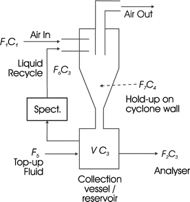
The complete system is shown in Fig. 1. It consisted of a sampler head consisting of a pair of circular metal plates (A) attached via plastic tubing to a glass cyclone (B). Air was sucked through A and B using a commercial vacuum cleaner (C). The rate of airflow was monitored using an orifice plate and adjusted as needed. A needle (D) was attached to B and buffer solution was pumped through its orifice using an adjustable peristaltic pump (E). As air flowed through the cyclone this jet of water covered the inner surface of the cyclone and flowed into a reservoir (F) from which it was recycled via E back into the cyclone. More details of design of the cyclone and its ability to capture the required aerosols are given below.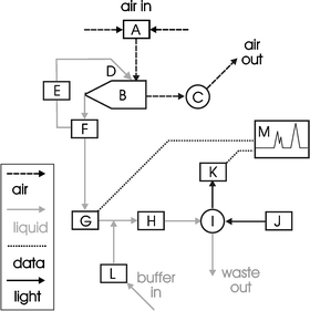 | ||
| Fig. 1 Schematic representation of the monitoring system (enzyme sniffer) for airborne enzymes. | ||
Following air sampling, known volumes of buffer are taken periodically from F into an automated flow injection system (G) attached to a bioreactor within a thermostatically controlled column heater (H). Downstream is located an optical flow cell (I) equipped with two optical fibres attached to a light source (J) and a spectrophotometer (K). Phosphate buffered saline is passed through the FIA system using a peristaltic pump (L) and the signal from K recorded using a lap top PC (M). This PC also controlled the automated flow injection system. In both cases the programmes used were those supplied by the manufacturer of these two systems (FIAlab, Medina, WA, USA).
The automated flow injection system (G) was model 3500 from FIAlab Instruments. The column heater (H) was an Eppendorf CH500 heater (Phenomenex, Macclesfield, Cheshire, UK), which was set to operate at an exit buffer temperature of 40 °C at a flow rate of 0.7 ml min−1. The flow cell (I) was model X from FIAlab who also supplied the two stainless steel-coated optical fibres (P400-2), the LS-1 tungsten halogen light source and the S2000 spectrometer (J). The peristaltic pump (K) was model P-1 from Pharmacia (Milton Keynes, Buckinghamshire, UK).
Design and efficiency testing of the cyclone
A glass cyclone of dimensions (40 mm diameter, 20 mm outlet, 30 × 10 mm rectangular inlet, and a main body of 80 mm length and cone of 80 mm length) was constructed which had three pre-drilled holes in the air inlet tube to allow up to three positions of the needle for the introduction of the recycling fluid (see Fig. 2). These holes were positioned at the centre of the inlet tube and 6 mm either side. A stainless steel hypodermic needle was bent at a right angle (10 mm from tip) to allow the recycling fluid to be pumped into the cyclone.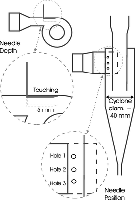 | ||
| Fig. 2 Design of the glass cyclone used in the studies showing the positioning of recycling fluid needle entry points. | ||
The cyclone was tested to measure its grade efficiency by loading fine dust through the cyclone inlet and measuring the difference in particle size and concentration of the dust inputted into the cyclone and that of the dust exiting the cyclone using an aerodynamic particle sizer (APS).
Variable airflows were drawn through the cyclone using a variable flow vacuum pump. The air flow was measured across the entrance to the tubing using a 20 mm diameter bell mouth.
The fine dust, R10 mineral flour (http://www.particletechnology.com) had a particle size of no greater than 10 μm. The dust was aerosolised using a TOPAS SAG 410 (http://www.topas-gmbh.de) into the rig using a pitot tube at approximately 0.1 g min−1.
The air was sampled either side of the cyclone using isokinetic sampling tubes. These were placed at least 10 diameters after any bends, valves or any changes in pipe diameter. Samples were taken using an APS (TSI APS 3320, http://www.tsi.com) at a flow of 5 l min−1.
The APS was set to sample for 20 s with a 10 s interval between samples, the first sample was taken from the isokinetic sampler before the cyclone, the sampling valve was then switched and the next sample was taken from the airflow after the cyclone, following this the sampling valve was switched. This cycle was repeated a total of 10 times with 10 samples taken from the air flow before the cyclone and 10 samples after.
The percentage efficiency of the cyclone at a set flow rate was calculated by subtracting the number of particles at a distinct particle size exiting the cyclone from those entering the cyclone. For example, if at a distinct particle range of 0.523–0.640 μm 10![[thin space (1/6-em)]](https://www.rsc.org/images/entities/char_2009.gif) 000 particles were sampled from the air entering the cyclone and 9000 particles were measured exiting the cyclone, then the percentage efficiency at that particle range would be 10%.
000 particles were sampled from the air entering the cyclone and 9000 particles were measured exiting the cyclone, then the percentage efficiency at that particle range would be 10%.
The grade efficiency for the cyclone at a set flow rate was found by calculating the efficiency across the entire range of the particle sizes measured. This grade efficiency is represented graphically as a curve with percentage efficiency plotted against particle size in microns (not shown).
The d50 of a cyclone at a set flow rate was found by plotting a best fit curve through the points of grade efficiency curve and deriving the particle size where the cyclone is 50% efficient.
Reagents and materials used in the flow injection analysis system
The composition of buffers, sources of enzymes, and chemicals and other materials used in the flow injection system and in bioreactor production are those described previously.6–9 Gelatin type B (about 75 bloom) was from Sigma (Poole, Dorset, UK). Texas Red® succinimidyl ester was from Molecular Probes (Eugene, OR, USA). The serine-type proteolytic enzymes studied were Purafect (Genencor International Inc., Rochester, USA) and Savinase from Novozymes, Bagsvaerd, Denmark, who also supplied the lipase and cellulase enzymes. Papain was from Papayer Latex and supplied by Sigma.Activated cellulose (2.5 g after filtration) was suspended in 0.1 M anhydrous dibasic sodium phosphate buffer (65 ml). To this was added the gelatin–Texas Red conjugate (10 ml). The container was coated in aluminium foil and rotated for 45 min at room temperature prior to the addition of sodium cyanoborohydride (250 mg). The tube was replaced on the rotator and left to mix overnight at room temperature. After coupling, the cellulose–gelatin–Texas Red solid phase was filtered under vacuum as above and washed with 2 l of deionised water. The resulting cellulose–gelatin–Texas Red solid phase was also stable for 3–4 weeks when stored under refrigerated in deionised water containing 0.02% sodium azide. Bioreactors were produced as described in ref. 8.
Development of the flow injection analysis system
Performance of the complete system in-house
In the second study, an identical bioreactor was used and the system was run continuously for 21 days during which it was calibrated with 0, 5, 10 and 25 ng ml−1 duplicate injections of Savinase standards at the start and end of each daytime run with the same standards injected 6 h after the start but as single standards. At the end of the run the system was flushed with FIA buffer, the column heater turned off and the flow rate reduced to 0.2 ml min−1 until the next run was performed. On the following days, the FIA system was set up to operate as described above and the process repeated. From this experiment it was possible, to calculate the total mass of Purafect and Savinase injected through the respective columns over the test periods.
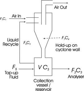 | ||
| Fig. 3 Schematic of fluid flows in the cyclone. F1 air flow rate in; C1 concentration of enzyme in air; C2 concentration of enzyme in air leaving cyclone due to non-capture; F4 liquid flow lost through re-entrainment; C3 concentration of enzyme in collection reservoir and re-entrainment fluid; F3 liquid flow rate lost through evaporation; F7 liquid flow from cyclone walls into collection vessel; V liquid volume of collection reservoir kept constant with top-up flow, F5; F2 liquid flow to enzyme analyser and F6 recycle fluid flow rate. | ||
| F5 = F2 + F3 + F4 | (1) |
| F6 = F3 + F4 + F7 | (2) |
(i) Those particles not captured by the cyclone through its design specifications, and
(ii) those particles which have splashed off the wall of the cyclone and have been swept out of the cyclone outlet (re-entrainment). This would be a characteristic for cyclones with a liquid wash stream only.
The aerosol captured by cyclone can thus be calculated as
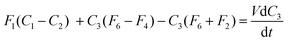
| F1 (C1 − C2) − F4C3 | (3) |
| F6C3 + F1(C1 − C2) = F7C4 + F4C3 | (4) |
 | (5) |
| F7C4 = F1(C1 − C2) + C3(F6 − F4) | (6) |
 | (7) |
 | (8) |
 | (9) |
Inverting the logarithms and rearranging to give C3,
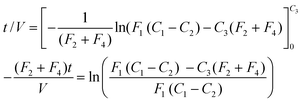
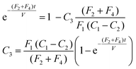 | (10) |
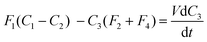
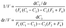
 . The characteristic time of the system is,
  . To increase the sensitivity of the system t
→ 0, therefore sensitivity can be increased by a reduction in the size of V, or by increasing the liquid flows from the collection vessel. Of these options, reducing the collection volume is the most practical way of increasing the sensitivity.
. To increase the sensitivity of the system t
→ 0, therefore sensitivity can be increased by a reduction in the size of V, or by increasing the liquid flows from the collection vessel. Of these options, reducing the collection volume is the most practical way of increasing the sensitivity.
 | (11) |
 | (12) |
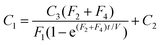
The predicted performance of the device was obtained using eqn (8) by taking the gradient of C3 − t at regular intervals. This is the concentration that the detection system would have to measure. The cyclone concentrates the enzyme in the reservoir as expected, but then the concentration decreases in a linear fashion due to the feed to the detection system and any re-entrainment losses (the reservoir volume is maintained constant through a top-up system of fresh buffer). In practice, a 5 min sampling strategy was adopted because the flow injection analysis of the enzyme needs to include not only a sample injection but a wash phase as well.
 | ||
| Fig. 4 Schematic of the flows for determining re-entrainment losses from the cyclone system. F1 and F2 are the air flow rates entering and leaving the cyclone, respectively; F5 top-up fluid flow rate to keep volume (V) in collection reservoir constant; C3 concentration of dye in reservoir; F3 fluid loss through evaporation and F4 re-entrainment losses. | ||
 | (13) |
 | (14) |
The experiments were carried out by the setting up of the equipment as above with the addition of tartrazine (see experiments below for timings and concentration used), absorbance readings from the spectrophotometer were taken regularly throughout the experiment, and the mass of the liquid reservoir was recorded at time intervals of approximately 10 min.
Fluid loss was investigated by measuring of change in mass in the reservoir bottle over a number of minutes or hours of the experiment, whilst fluid was passed through the cyclone, into the collection vessel and through the flow cell. The change in the concentration of the tartrazine was measured using the absorbance of the dye in the flow cell (λ = 510 nm).
Three sets of experiments were carried out using this equipment and methodology to establish the ability of the model to predict the change in concentration within system given varying concentrations of solute in the system:
(i) A single dose of 10 mg of tartrazine was added at 5 min into the experiment, as an aliquot of 0.1 ml at a concentration of 0.1 g ml−1.
(ii) A constant dose of tartrazine at a rate 0.1 mg min−1 over the experimental run.
(iii) Three doses of 10 mg of tartrazine were added at 5, 65 and 185 min into the experiment as an aliquot of 0.1 ml at a concentration of 0.1 g ml−1.
The resulting data was plotted as tartrazine concentration vs. time, whilst the modelling data was developed from inputting the required values into the method outlined in above. The resulting experimental and modelling data were plotted on the same figures (Fig. 5a, b and c). Several sets of experimental and modelling data are plotted together.
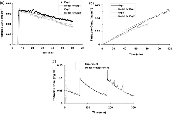 | ||
| Fig. 5 (a) Experimental data of a pulse of solute (tartrazine) added at 5 min to new enzyme sniffer system with modelling data overlaid. (b) Experimental data of constant addition of solute (tartrazine) to enzyme sniffer system with modelling data overlaid. (c) Experimental data of 3 pulses of solute (tartrazine) added to enzyme sniffer system with modelling data overlaid. | ||
The filters from the Galley samplers were removed and following standard in-house methods of extraction and analysis by used by the company, the time-averaged airborne concentration of Purafect was calculated.
Results
Design of the air sampling system and use of the modelling equation
With respect to the total fluid loss, the significant parameters (p = 0.05, Student t-tests) were air flow rate and the recycle flow rate; increasing either increased the rate of fluid loss. This is not unexpected, since the higher the air flow rate, the greater will be the evaporation effect. Similarly a high recycle rate will wet more of the cyclone surface and hence cause a higher evaporation loss. In the case of the re-entrainment losses, the significant factors were airflow rate, needle depth and the interaction between these two. By positioning the needle on the cyclone wall, less fluid was lost from the system by re-entrainment at high flow rates than when the needle was releasing the fluid from the axes of the cyclone inlet tube.10
It can be seen in all three figures presented in Fig. 5, that the model predicts the experimental data well. With both pulse experiments (shown in Fig. 5a and c) the model predicts a build up before the actual real data, this may be due to some delay within the real system either computer based or in the collection of the data from the spectrophotometer, the real data also show a larger pulse than that of the modelled data.
Several spikes can be seen towards the end of both experimental data sets in the triple pulse experiments (Fig. 5c). These are caused by delays in the addition of fluid to the system, caused by intermittent foaming during these experiments. Once the foam level drops, the top-up system quickly adds liquid, which subsequently reduces foaming and replenishes the fluid level within in the CV and overall sampling system; this dilutes the exaggerated dye concentration.
The constant build-up experiment (Fig. 5b) represents two different experimental data sets; one when modelled predicts the build-up fairly well throughout the curve (representative within 8% of the real data), whilst the other data set predicts both the beginning and end of the curves better (representative within 10% of the real data, respectively). These differences are most likely due to the variation of the entrainment figure throughout the experiment. The entrainment can vary by a few percent from the beginning of the experiment till the end; this could have this effect on the prediction of real data using the model.
Assay performance
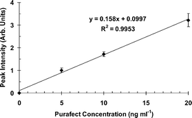 | ||
| Fig. 6 Typical calibration curve of fluorescence intensity versus enzyme concentration. | ||
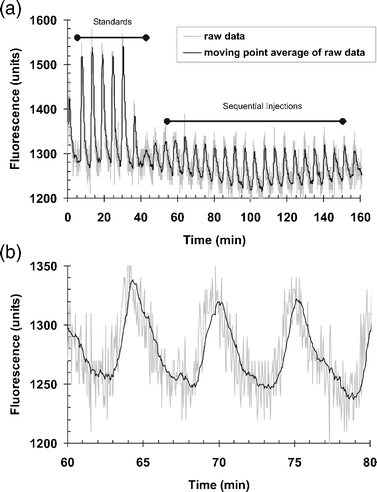 | ||
| Fig. 7 Typical response pattern of the FIA system to repeated injections of replicates of Purafect standards (60 ng ml−1n = 5, and 20 ng ml−1n = 21) over an extended run (2 h). | ||
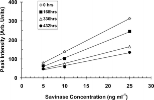 | ||
| Fig. 8 Calibration plots during the continuous operation of the flow injection analysis system over 21 days. | ||
Performance of the system in industry
No significant signals were produced by the system when it was used on four occasions for up to 4 h at sites 1 and 2. The results from the Galley sampler ranged from 1.3–2.7 ng m−3 for these air samples which are below the LOD for the system. During one further experiment at site 2, no peaks were observed during the first 80 min of sampling. Two samples of crushed washing powder containing enzyme were then thrown into the space between the two samplers at times 85 min and 180 min, when two peaks were then seen at 90 min and 185 min. The time averaged results for the Galley sampler was 5.7 ng m−3 and the corresponding value for the new system was 2.8 ng m−3. Three sampling sessions were undertaken at site 3. In the first, peaks between 5–20 ng m−3 were observed as shown in Fig. 9. This coincided with activities within the factory. As shown in this figure, the system was routinely calibrated at the beginning and end of each run by replicate injections of standards. Fig. 10 shows the corresponding concentrations of enzyme with time for the interpolated airborne concentrations, and the time-averaged airborne concentrations from the Galley samplers. The Galley sampler showed a time-averaged concentration of 0.49 ng m−3 over the 190 min sampling period. The new system exhibited three peaks; a major peak of 21 ng m−3 at the beginning and minor peaks of 8, 7 and 6 ng m−3 thereafter. The calculated time averaged concentration for the new system was 1.73 ng m−3. On the two other occasions, no significant peaks were observed on the first (Galley result of 0.18 ng m−3). On the second occasion no peaks were seen up to 130 min when dust collected from the factory floor and from surfaces was thrown into the gap between the two sampling systems. This produced a large peak of 1200 ng m−3 at 135 min. The time averaged results were 6.9 ng m−3 for the Galley and 25.5 ng m−3 for the new system.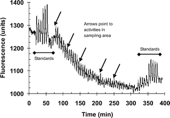 | ||
| Fig. 9 A signal–time response profile obtained during monitoring for airborne proteolytic enzyme at an industrial site. Two sets of standards (25 and 50 ng ml−1) were injected at the beginning (n = 3) and end (n = 5) of the run. | ||
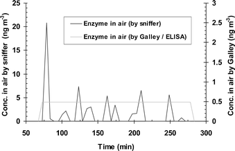 | ||
| Fig. 10 A concentration–time profile interpolated from results obtained from Fig. 9. The dotted line represents the concentration of proteolytic enzyme in the reservoir/collection vessel of the system (F in Fig. 1) and the continuous line the interpolated concentration of enzyme in the air. | ||
Discussion
We wanted a high-volume sampler (to match current industrial practice) that could deliver the aerosol into a solution which in turn could be pumped to a flow injection enzyme detector. A cyclone air sampler fulfils these requirements. We have already reported the use of a cyclone for the non-continuous monitoring of protease aerosols.7 There are a number of problems associated with the use of a cyclone for continuous sampling, however. These were highlighted in a seminal paper by Errington and Powell11 who used large (350 l min−1) and small (75 l min−1) cyclones to sample aerosols of bacteria and spores. They concluded that the cyclone collection system was as efficient as other samplers (e.g. an impinger) for this application. Griffiths12 and his group have thoroughly investigated and reviewed the use of large throughput cyclones (750 l min−1) to collect bioaerosols in a series of papers and identified parameters that were needed to operate the systems efficiently.It was concluded from this published work that if we were going to monitor the air borne concentration of enzyme from the concentration in the reservoir on a continuous basis, we either had to measure the volume of collection fluid continuously or keep the collection fluid volume constant. We opted for the latter approach.
Via an iterative experimental process the final cyclone design used in this study was adopted10 and the resulting cyclone connected to an air sampling inlet system that was based on the proven high volume Galley sampler. This is designed to mimic human respiration when operating at an sampling rate of about 600 l min−1 and at an inlet flow of about 1 m s−1.13
The complete cyclone sampler was adapted to operate continuously by:
(i) Using a wash fluid which is recycled from the reservoir;
(ii) Keeping the collection volume constant by adding fresh collection fluid from a storage tank;
(iii) Pumping out some of the reservoir fluid to measure the enzyme concentration continuously or at regular intervals;
(iv) Developing a model to relate the airborne concentration to the reservoir concentration.
The optimisation of the cyclone sampler set-up was a compromise between the need to operate at high air flow rates and the need to minimise fluid losses. In order to collect the enzyme at a high efficiency then the air flow needs to be high, whilst to minimise loss of fluid requires low air flow and low recycling rates. In order to understand the affects of these conflicting requirements on the performance of the cyclone and the entire system, further research was undertaken as described more detail in ref. 10. The operating conditions described herein reflect the outcomes of those studies.
It was demonstrated that the mathematical model developed to calculate the concentration of captured solute during prolonged air sampling was accurate. Thus when tartrazine dye was added under three different conditions (continuous, delayed, and intermittent) to the collection vessel of the air sampling system and the system operated under the normal conditions of air flow, sampling and buffer top up, the concentration of the dye actually measured agreed well with the profile of solute concentration predicted by the model (Fig. 5a, b and c). Thus the prediction from eqn (10), that for a constant enzyme concentration a steady state concentration will be reached, was observed. This gives confidence in the modelling represented above and the use of the model to predict the aerosol concentration of enzymes within the factory experiments.
Within the analytical system a new substrate was used to produce the required signals. Gelatin was conjugated with Texas Red® to produce a fluorescent label that was then covalently immobilised onto a cellulose support matrix. Gelatin was chosen as the substrate because it provides many sites for fluorescent conjugation and potential enzyme hydrolysis. Upon exposure to subtilisin-like protease enzymes, proteolytic cleavage of the immobilised gelatin occurred, resulting in fluorescent signals that were recorded by the spectrophotometer.
The apparatus described constitutes a novel near real-time system for determining the airborne concentration of subtilisin-like protease enzymes in industry. The analytical system has been optimised with respect to sampling volume (100 μl) and flow rates (0.7 ml min−1) to obtain good sensitivity with low sampling time intervals (5 min) when used in combination with the air sampling system.10 The buffer chosen is suitable for maintaining the protease activity of the enzyme and the fluorophore signal. Its use also minimises the leaching of fluorophore, thus extending the lifetime of the bioreactor (data not shown).
The sensitivity of the assay and linearity of the standard curves were good. Linearity of the responses was demonstrated over the enzyme range 5–60 ng ml−1 (equivalent to airborne levels of 5–60 ng m−3)7 and the LOD was calculated to be 4.8 ng ml−1. This is equivalent to an airborne concentration of nearly an order of magnitude below the current MEL for subtilisin-like protease enzymes.
Excellent specificity has been demonstrated for subtilisin-like protease enzymes when compared to other classes of enzyme. No signal was observed with cellulase indicating that hydrolysis of the solid phase support material in the bioreactor did not occur under the conditions use in the FIA system. Also no signals were seen with lipase which, like cellulase, is also used in the detergent industry and thus could be present in the work place atmosphere.
The system has good within-assay precision and reasonable within and between batch variability. The variation stems mainly from inconsistent packing of the columns during manufacture of the bioreactors. This is currently performed manually but an automated system would probably lead to much improved batch consistency.
It was shown that the system became significantly desensitised after exposure of the bioreactor to about 200 ng of Purafect and Savinase. In practice if the system is calibrated with single sets of standards at the beginning and end of each run then it could be run for 18 days if no enzyme is captured from the air. If there is a constant airborne concentration of 6 ng m−3 then the bioreactor will be depleted after 24 h. Transient release of a high airborne concentration of enzyme above 2 μg m−3 will cause a very large signal and immediate depletion of the bioreactor. The inherent stability of the flow injection analysis system with the bioreactor attached was demonstrated by its continuous use for 21 days.
The system is relatively portable and has successfully been demonstrated over extended periods under industrial conditions. However the major advantage of this system over current standard industrial methods is that it provides a near-continuous record of airborne concentrations of enzyme throughout the sampling period. The system is a near time system, with responses of 5 min and a capacity for continuous monitoring over 8 h periods under industrial conditions.
The benefit of the system is clearly demonstrated from the results of the industrial trial. In Fig. 10, the time-averaged airborne concentration seen with the Galley sampler over the 3 h of the run was only 0.49 ng m−3 which is well below the MEL of 40 ng m−3. However the time-airborne concentration profile also shown in Fig. 10 obtained with the new system shows a significant peak of 21 ng m−3 at the beginning of the monitoring period that was detectable for about 10 min. This may have been due to activities that were being undertaken within the factory at that time, but further observations are needed to verify this observation. It is possible that exposure to such transient releases of enzyme within the factory could lead to sensitisation of workers.
The correlation between the time averaged results observed for the new system and the Galley sampler during the industrial sampling was satisfactory since they were within an order of magnitude for the three sets of data obtained. It is not expected that these results will be identical since each sampler may have been exposed to different plumes of air with different concentrations of enzyme. Also the efficiency of collection of the two systems may not be identical and the analytical systems used may not have had the same specificity profiles. Further studies are planned to obtain additional correlation data between these two systems in industry.
Acknowledgements
Partial funding is acknowledged from Unilever, Procter and Gamble, Novozymes and Genencor. The massive contribution to this study of Robert Cumming who died shortly after its completion is acknowledged.References
- M. K. Schweigert, D. P. Mackenzie and K. Sarlo, Clin. Exp. Allergy, 2000, 30, 1511 CrossRef CAS.
- P. Cullian, J. M. Harris, A. J. Newman, A. M. Hole, M. Jones, F. Barnes and G. Jolliffe, Lancet, 2000, 356, 1899 CrossRef CAS.
- L. C. Kenny, A. Bowry, B. Crook and J. D. Stancliffe, Ann. Occup. Hyg., 1999, 43, 393 CAS.
- http://www.hse.gov.uk/pubns/aboutus/hsc/iacs/acts/130303/paper08.pdf .
- EH40/2005 Workplace Exposure Limits, Health and Safety Executive Books, Merseyside, 2005, ISBN 0 7176 2977 5 Search PubMed.
- D. Sykes, L. Grieveson, R. H. Cumming and F. J. Rowell, J. Aerosol Sci., 2000, 31, S90–91.
- L. X. Tang, F. J. Rowell and R. H. Cumming, Analyst, 1995, 120, 1949 RSC.
- L. X. Tang, F. J. Rowell and R. H. Cumming, Ann. Occup. Hyg., 1996, 40, 381 CrossRef CAS.
- L. X. Tang, F. J. Rowell and R. H. Cumming, Anal. Proc. incl. Anal. Comm., 1995, 32, 519 RSC.
- D. Sykes, The Development of a Bioaerosol Sampler for the Detection of Enzymes in Industry, PhD thesis, University of Teesside, 2005 Search PubMed.
- F. P. Errington and E. O. Powell, J. Hyg., 1969, 67, 387 Search PubMed.
- W. D. Griffiths, I. W. Stewart, S. J. Futter, S. L. Upton and D. Mark, J. Aerosol Sci., 1997, 28, 437 CrossRef CAS.
- http://www.newtongroup.co.uk .
Footnote |
| † We report with regret that Robert Cumming died in 2002. |
| This journal is © The Royal Society of Chemistry 2007 |