Depth profiling of calcifications in breast tissue using picosecond Kerr-gated Raman spectroscopy
Rebecca
Baker
a,
Pavel
Matousek
b,
Kate Louise
Ronayne
b,
Anthony William
Parker
b,
Keith
Rogers
c and
Nicholas
Stone
*a
aBiophotonics Research Group, Gloucestershire Royal Hospital, Great Western Road, Gloucester, UK GL1 3NN. E-mail: n.stone@medical-research-centre.com; Fax: 01452 395713; Tel: 01452 395712
bCentral Laser Facility, CCLRC Rutherford Appleton Laboratory, Didcot, Oxfordshire, UK OX11 0QX
cCranfield University, Royal Military College of Science, Shrivenham, Swindon, UK SN6 8LA
First published on 28th November 2006
Abstract
Breast calcifications are found in both benign and malignant lesions and their composition can indicate the disease state. Calcium oxalate (dihydrate) (COD) is associated with benign lesions, however calcium hydroxyapatite (HAP) is found mainly in proliferative lesions including carcinoma. The diagnostic practices of mammography and histopathology examine the morphology of the specimen. They can not reliably distinguish between the two types of calcification, which may indicate the presence of a cancerous lesion during mammography. We demonstrate for the first time that Kerr-gated Raman spectroscopy is capable of non-destructive probing of sufficient biochemical information from calcifications buried within tissue, and this information can potentially be used as a first step in identifying the type of lesion. The method uses a picosecond pulsed laser combined with fast temporal gating of Raman scattered light to enable spectra to be collected from a specific depth within scattering media by collecting signals emerging from the sample at a given time delay following the laser pulse. Spectra characteristic of both HAP and COD were obtained at depths of up to 0.96 mm, in both chicken breast and fatty tissue; and normal and cancerous human breast by utilising different time delays. This presents great potential for the use of Raman spectroscopy as an adjunct to mammography in the early diagnosis of breast cancer.
Introduction
1.1 Calcifications in breast cancer
Calcifications are present in many different biological tissues, forming both as natural products (e.g. in bones and teeth) and in soft tissues as a result of disease. Calcifications are present as a mineralization product in bone, and consist of the specific mineral hydroxyapatite (HAP). Pathological calcifications are associated with many medical conditions such as diabetes, breast cancer and crystals-associated osteoarthritis.1 The deposition of calcium crystals on cells induces detrimental cellular effects and speeds up the progression of the associated diseases.2,3 Several studies have been carried out using different techniques to examine calcifications forming inside breast tissue, but as yet their formation mechanisms and biological impact on the tissue remains unclear.4–6 The presence of calcifications on mammographs is a feature of particular diagnostic significance, as sometimes this may be the only marker of a malignant breast lesion. Mammography can detect small masses, areas of distortion, ill-defined densities and microcalcifications not detectable by physical examination. However, as this relies only on the morphology of the specimen, it has no definitive criteria for classifying benign and malignant calcifications.In order to distinguish between benign and malignant calcifications by mammography, the size, number, shape, localisation and mode of grouping between microcalcifications are used. These criteria were not very specific and were taken into account in Le Gal's classification.7–9 Therefore there is a need for a more differential diagnosis.
It has in fact been found that only 10–25% of mammographically detected lesions are found to be malignant upon needle biopsy.10
Microcalcifications can be divided into two types; type I, which consist of calcium oxalate dihydrate (COD) (also termed Wedellite), and type II deposits, which are composed of calcium phosphates, mainly calcium hydroxyapatite (HAP). At present, there is no reliable way to distinguish between these two types of calcification by mammography, but the type is thought to correlate with disease.4,11–13Calcium oxalate crystals are mainly found in benign ductal cysts and are rarely associated with malignancy.14,15 Radiologically, calcium oxalate is characterised as amorphous and low to medium density.16 It appears that radiologically, low density, amorphous calcifications even if clustered are associated with benign breast disease.16 Although type I microcalcifications have been found in malignant breast lesions, specifically, lobular carcinoma in situ, it is extremely rare.9,13 Type II microcalcifications (calcium hydroxyapatites) can occur in both benign and malignant lesions13 but are seen most frequently in proliferative lesions including carcinomas.5,9,13 Radiologically, type II calcifications appear at a medium to high density and are histologically basophillic and non-birefringent. Calcifications consisting of hydroxyapatite are thought to arise from cellular degeneration or necrosis 14 and are estimated to occur 2–3 times more frequently than calcium oxalate.
It has been shown that type I and II calcifications can be distinguished in breast tissue based on their Raman spectra. It was also seen that type II microcalcifications found in benign ducts appear to contain a larger amount of calcium carbonate and a smaller amount of protein that type II microcalcifications found in malignant areas.13
As there are differences in chemistry between these two types of calcification, and subtle changes in the spectra of type II calcifications occurring in benign and malignant breast lesions, significant insight may be gained by using vibrational spectroscopy to probe their biochemical composition. If such a technique can be utilised in vivo, this will enable a more simplistic decision for diagnosing breast lesions and will reduce the patient trauma, time delay, and high medical costs associated with the biopsy of benign lesions.
1.2 Raman spectroscopy
Raman spectroscopy is a sensitive analytical technique capable of providing highly detailed biochemical information on a tissue sample. The technique relies on extracting chemical information from a sample based on its molecular specific Raman emission spectrum, resulting from molecular vibrations excited by incident monochromatic light. Raman spectroscopy has been well established as a powerful in vitro method for studying biological tissue and diagnosing disease.17 Previous experiments have demonstrated the ability of Raman spectroscopy to distinguish between normal and malignant breast tissues13,6 and between different grades of breast and other epithelial tissues.18–23 It has recently been shown that Raman spectroscopy is capable of distinguishing between the two types of calcification in excised breast tissue, and also distinguishing between the types of lesion (benign vs. malignant) with a high degree of accuracy.13 However as the technique is performed on excised tissue samples (in vitro), it is currently unclear whether it can be applied to detect and distinguish microcalcifications in vivo and non-destructively, although the power and excitation wavelengths used are non-destructive to tissue (when employing NIR radiation at a wavelength of 830 nm), which make it particularly amenable to in vivo diagnostics.Clinical applications of Raman spectroscopy have been limited, primarily due to the lack of optical fibre probes capable of effectively acquiring Raman spectra from tissue within the body. Therefore, the majority of in vivoRaman spectroscopy research has been confined to easily accessible organs and tissues such as the skin,24–26 and the cervix.27 In order to monitor tissue sites within the body, flexible, small diameter optical fibres must be used to deliver light to the tissue and collect the returning light. Because the probability of Raman scattering is so small, unique challenges must be considered in the design of Raman probes. The recent development of efficient, high-throughput, low-background optical fibre probes provides the opportunity to obtain in vivo tissue analysis capable of collecting and processing Raman spectra in less than 2 s.17
This study investigates the ability to obtain Raman spectra from beneath the tissue surface, which is needed for the detection of microcalcifications inside breast tissue. This will give information on both the distance through the breast tissue which can be probed, and the chemistry of the calcifications beneath the tissue surface.
1.3 Kerr-gating
One of the main problems with the use of Raman spectroscopy for in vivo measurements of biological tissue is that the collected Raman signal decreases when probing at greater tissue depth, causing the surface Raman signal and fluorescence to be significantly stronger than the sub-surface Raman signal. The Kerr-gating technique28 can be used for both temporally rejecting longer lived fluorescence in samples, and for depth profiling of the Raman spectra of biological tissues. It utilises impulsive Raman excitation with a picosecond pulsed laser, combined with a fast temporal gating of the inelastically scattered (Raman) light collected at different time delays following the laser pulse.29–32For Raman depth profiling, both the incident laser photons have to be able to migrate to a given depth within the tissue; and the Raman scattered photons have to migrate back to the surface. In this way Raman spectra from differing depths within the tissue will emerge at different times, enabling separation in the temporal domain.31 It is therefore possible to detect underlying structures through overlying tissue by the rejection of early photons.
Several studies have been performed demonstrating the ability of Kerr-gating to suppress fluorescence and produce time-resolved enhancement to improve spectra collected from cortical bone tissue and allow depth profiling.33–35 Experiments have also demonstrated the depth resolving power of this technique on powders31 as well as through prostate and bladder tissues to measure uric acid and urea in quartz cells and also from dark tissues such as the kidney and liver which are highly fluorescent using Raman spectroscopy at NIR and visible wavelengths.28
This study aims to investigate the use of Kerr-gated Raman spectroscopy for depth profiling of calcifications through breast tissue; as this has the potential to be used in vivo to differentiate between benign and malignant breast lesions.
Experiment methods
2.1 Preparation of calcification standards
Polycrystalline standards were purchased of ‘pure’calcium hydroxyapatite (HAP) and a 3.5% carbonate substituted hydroxyapatite (COHAP). The powders were placed into UV-grade quartz 300 µm thick vials specifically designed for measurement with Kerr-gated Raman spectroscopy .Calcium oxalate dihydrate (COD) is difficult to manufacture due to its inherent thermodynamic instability. As COD and calcium oxalate monohydrate are the main components of renal stones, the renal stones of animals (previously shown by X-ray diffraction studies to consist of COD) were crushed into powder (with a small particle size, much like microcalcifications) and placed into vials as above. HAP, COHAP and COD were measured through slices of normal chicken breast tissue, chicken fatty tissue, and normal and malignant human breast tissue.
2.2 Tissue collection and preparation
Chicken breast and fatty tissue were used in the model due to their homogenous nature. Tissue samples were prepared using a catering meat slicer, however, the accuracy of the thickness cut was poor. Therefore the thickness of the tissue was carefully measured between two glass slides with a micrometer. Normal fresh chicken breast was obtained and a small section cut to 0.9 mm thick. A small section of fatty tissue was also cut to 0.96 mm, and sections were mounted between two fused silica slides 100 µm thick. The samples were stored in a refrigerator and warmed to room temperature before use.Human breast tissue was obtained with ethical approval from patients undergoing mammography at Gloucestershire Royal Hospital. The samples were then snap-frozen in liquid nitrogen and transferred to an –80 °C freezer for storage. At the time of the experiments, the tissue was allowed to warm to room temperature and sections were cut and placed between 2 fused silica slides of 100 µm thickness. A normal slice of 0.58 mm and a malignant slice of 0.31 mm thick were used in this work; these slices were cut with a scalpel as a freezing microtome is usually limited to sections up to around 30 µm and the human specimens were too small for the catering slicer.
2.3 Experimental
This study was performed with a 490 nm probe beam. There were inherent technical difficulties with using NIR excitation, the ideal wavelength range for pentration in tissue, due to the need for an 800 nm gating pulse to trigger the Kerr-cell. 490 nm was selected to provide a proof-of-concept, with the objective of optimising the Kerr-gate system for NIR studies in the future.The Kerr gate system is based on a high throughput 4 ps optical Kerr shutter described in more detail in previous publications.36 The set up of the Kerr gate consists of a 2 mm long cell filled with CS2 and two 41 × 41 mm Glan Taylor cross-polarisers, coupled to a conventional Raman spectrometer (Triplemate) (see Fig. 1). When the Kerr gate is closed, the polarisers are in cross orientation, therefore the light from the sample is blocked. When the gate is opened by a short 1 ps gating pulse at 800 nm, a transient anisotropy within the CS2 acts as a λ/2 waveplate rotating the light from the sample to the correct polarisation to transmit through the second polariser. The gating pulse is incident such that it bypasses the polarisers.
 | ||
| Fig. 1 A schematic diagram showing the optical arrangement of the Kerr-gated Raman system. | ||
The residual elastically scattered light from the 490 nm probe laser line is blocked from entering the spectrometer using a Kaiser holographic notch filter. The residual 800 nm gating beam was blocked by placing an almost saturated solution of copper sulfate in water in a 1 cm optical cell in front of the spectrometer .
The probe wavelength of 490 nm was provided by an optical parametric amplifier pumped using a second harmonic of a 1 kHz regenerative amplifier system operating at 800 nm with 1 ps pulse duration and a pulse energy of 2 mJ.31 The 490 nm beam was focussed into a 300 µm spot on the sample surface and the pulse energy at the sample was 5 µJ. The study was performed using a lens with an f-number of 2, in back-scattering geometry i.e. at 180° to the collection path which is best suited for biomedical diagnostic applications, because it allows illumination and collection from the surface of the material.29
Experiments were performed to obtain Raman spectra that could distinguish between type I (COD) and type II (HAP/COHAP) calcifications. The samples were placed into cuvettes (windows 300 µm thick) as above and measured alone (for 10 s with 5 acquisitions and 3 cycles) and through sections of chicken breast and fatty tissue; and through normal and cancerous human breast tissue (20 s with 10 acquisitions and 3 cycles) to demonstrate the ability to obtain Raman spectra from tissue layers. All spectra were measured using time delays of –50, –4, 0, 2, 5, 7, 10, 15, 20, 30, 50 and 100 ps. The time delays were randomised to prevent systematic error from any sample changes during the experiment. Negative time delays mean collecting the light signals at times before the pulse reaches the specimen surface. The measurement was repeated using the optimum time delay for the appearance of the calcification spectra through the tissue, and for a time delay of –50 ps for the background, at 20 s with 10 acquisitions and 15 cycles. All spectra were pre-processed by subtraction of the background spectrum and application of a 17-point Savitzky–Golay smooth.37
An approximation of the distance travelled in tissue at this wavelength was obtained previously.12 For each 1 ps time delay a distance of approximately 200 µm will have been travelled, however it is likely that up to 10 scattering events will have occurred in this time.
Results and discussion
Fig. 2a shows the Raman spectra measured from the cell containing HAP only. This indicates the primary spectral peaks characteristic of HAP. The peaks assigned to phosphate (PO4) vibrational modes of HAP at 958 (PO4v1) and 1040 cm–1 (PO4v3) are those which will be expected to appear when measured under sections of tissue/fat.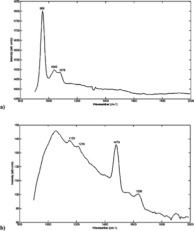 | ||
| Fig. 2 Raman spectrum at an excitation wavelength of 490 nm, taken from a quartz cell containing (a) pure HAP, (b) pure COD (measured with 0 time delays, 20 s acquisition time, 5 acquisitions and 5 cycles). Peaks at 958, 1040 and 1076 cm–1 can be assigned to PO42– vibration modes of HAP. Peaks at 1480 cm–1 and 1636 cm–1 can be assigned to vibration modes of COD. | ||
As the HAP measured is in pure form, it contains no carbonate peak between 1074–1078 cm–1 (resulting from the vibrational mode v1 CO3). However the width of the PO4v1 peak at 958 cm–1 is expected to change with different carbonate concentrations of HAP. The peak that is expected to appear, when there is some carbonate substitution of the phosphate (in COHAP), between 1074–1078 cm–1 may therefore be overlapped by the broad peak centred at 1041 cm–1, which is a characteristic vibration mode (v3) of the phosphate group.
Fig. 2b shows the spectrum of COD obtained using the Kerr-gated system. Relevant peaks appear at 1488/1478 cm–1 (COM/COD) and 1636 cm–1 (COD).37
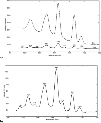
Fig. 3a shows the Raman spectra of HAP measured through 0.9 mm normal chicken breast at different time delays (0–30 ps) following the laser pulse. It can be seen that the peaks characteristic of breast tissue diminish as the time delay is increased (reflecting an increase in depth through the tissue) and peaks characteristic of HAP appear. The signal from the tissue is eventually lost, with peaks characteristic of HAP appearing at 956 cm–1 (representative of the PO4v1 vibration mode).
 | ||
| Fig. 3 (a) 3D plot showing the Raman spectra of HAP measured through a section of normal chicken breast (0.9 mm thickness) at different time delays (0–30 ps) following the laser pulse. (b) Raman spectrum of HAP through chicken breast (0.9 mm) measured at the optimum time delay (20 ps) following –50 ps spectrum subtraction. The symbol ‘*’ indicates visible HAP peaks. | ||
Fig. 3b shows the Raman spectrum of HAP through chicken breast measured at the optimum time delay (which in this case occurred at 20 ps). The optimal time delay was chosen for the detection of characteristic HAP peaks through the breast tissue without the total loss of spectral information. This is shown to give a clearer indication of the characteristic HAP spectra (which can be compared to that in Fig. 2a).
The appearance of HAP is indicated by the presence of a peak at around 958 cm–113,38–41 whilst the spectral characteristics of breast tissue are significantly reduced in intensity. Other peaks are also present at 1080, 1220, 1328, 1450, 1664 and 1742 cm–1. The peak at 1080 cm–1 is characteristic of the v1 vibration mode of carbonate from the HAP38,42 or may be representative of the phosphate from nucleic acids or phospholipids in the tissue. The rest of the peaks represent tissue spectra of protein (1220, 1664,43,44 1450 -CH2 and CH3 bending42), lipids (1450 -CH2 and CH3 bending,41,45–47 1742 -C![[double bond, length as m-dash]](https://www.rsc.org/images/entities/char_e001.gif) O ester carbonyl stretch42) but are decreased in intensity compared to the spectra at the zero time delay (which reflects spectra through the tissue only).
O ester carbonyl stretch42) but are decreased in intensity compared to the spectra at the zero time delay (which reflects spectra through the tissue only).
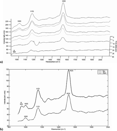
Selected Raman spectra of HAP through a section of 0.96 mm fatty tissue are shown in Fig. 4. From the plot in Fig. 4a, it can be seen that the spectra of fatty tissue also diminish as the time delay is increased. The appearance of the main HAP peak at around 961 cm–1 was most noticeable at a 20 ps time delay (Fig. 4b). This can be compared to the spectra at a time delay of 2 ps, where there is no clear indication of the HAP specific peak.
 | ||
| Fig. 4 (a) A plot showing the Raman spectrum taken at different time delays (2 and 20 ps) following the laser pulse, of HAP measured through a section of fatty tissue (0.96 mm). (b) Raman spectra taken at the optimum time delay (20 ps) for the detection of characteristic HAP peaks through the fatty tissue section. The symbol ‘*’ indicates visible HAP peaks. | ||
The Raman spectra of HAP through a 0.31 mm section of malignant human breast tissue are shown in Fig. 5. From the plot in Fig. 5a, it can be seen that the spectra of breast tissue also diminish as the time delay is increased. The spectra from the human breast tissue are dominated by carotenoid peaks at 490 nm excitation. The appearance of the main HAP peak at around 956 cm–1 was again most noticeable at 20 ps time delay (Fig. 5b). This can also be compared to the spectra at a time delay of 5 ps (most signal obtained from within the tissue), where there is no clear HAP specific peak.
 | ||
| Fig. 5 (a) 3D plot showing Raman spectra taken at different time delays following the laser pulse, of HAP measured through a section of malignant human breast tissue (0.31 mm). (b) Raman spectra taken at optimum time delays (5 and 20 ps) for the detection of characteristic HAP peaks. The symbol ‘*’ indicates visible HAP peaks. | ||
Fig. 6 shows the Raman spectra of a calcium oxalate dihydrate/monohydrate powder measured through a section of chicken breast. Peaks characteristic of calcium oxalate can be seen to appear clearly in the spectra taken at a 15 ps time delay. These appear at 1488/1478 (COM/COD) and 1633 cm–1 (COD).38 The peaks at 0 ps are consistent with chicken breast tissue spectra (and can be assigned to 1665 cm–1 -amide I,48,49 1240 cm–1 -amide III28).
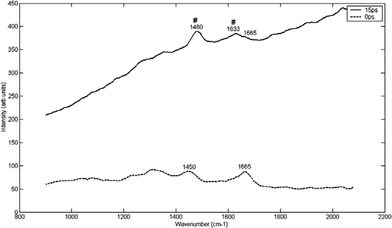 | ||
| Fig. 6 Raman spectra at different time delays (15 ps and 0 ps) following the laser pulse, of COD through a section of chicken breast tissue (0.9 mm). The optimum time delay for COD detection through the chicken breast tissue specimen was 15 ps (see discussion for explanation of peaks). The symbol ‘#’ indicates visible COD peaks. | ||
Fig. 7 also shows the resulting Raman spectra through 0.58 mm section of normal human breast tissue at 30 ps time delay. Peaks characteristic of COD appear at 1478 and 1636 cm–1. It is therefore possible to visually distinguish the peaks characteristic of calcium oxalate from those of the normal human breast tissue at this time delay. However it should be noted that these breast spectra are dominated by carotenoid peaks at 490 nm excitation. The use of non-resonant excitation should make the spectra much more similar to those obtained from the chicken tissues and therefore spectra from depth would be likely to match those shown in Fig. 4, 5 and 7. However, as stated in the experimental methods (above), technical difficulties with the Kerr-gated system prevented us from studying these specimens with near-infrared probe light. Furthermore the source of COM/COD was in this case renal stones, which contained fluorophores which at 490 nm added to the background signal. This would not be expected from breast calcifications at NIR wavelengths.
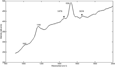 | ||
| Fig. 7 Raman spectra at 30 ps time delay, of COD through a section of normal human breast tissue (0.58 mm). The symbol ‘#’ indicates visible COD peaks at 1476 and 1634 cm–1. | ||
Conclusions
This study has demonstrated that it is possible to perform depth profiling of calcifications through breast tissue by using picosecond Kerr-gated Raman spectroscopy . By selecting a time delay which gives the clearest indication of the presence of Raman bands representative of calcifications, spectral bands characteristic of calcium oxalate and hydroxyapatite, the main components of type I and type II calcifications respectively can be easily resolved. Further studies will be conducted to determine whether spectral features can associate the presence of type II calcifications with benign or malignant tissue. One such study has shown that it is possible to distinguish type II microcalcifications occurring in benign and malignant human breast tissue with high sensitivity and specificity,11 using principal component analysis and logistic regression to examine carbonate content and the width of the main phosphate band at 960 cm–1.As this study has shown, the two types of calcification can be differentiated based on their Raman spectra through both fatty and protein rich tissues. This could have major implications for the future use of Raman spectroscopy in vivo. If type II calcifications can be distinguished in benign and malignant breast tissue, this will represent a possibility for the use of Raman spectroscopy in vivo as a tool for diagnosis.
References
- Y. Sun, X.-R. Zeng, L. Wenger and H. S. Cheung, Biochem. Biophys. Res. Commun., 2003, 312(4), 1053–1059 CrossRef CAS.
- Y. Sun, X. R. Zeng, L. Wenger and H. S. Cheung, Biochem. Biophys. Res. Commun., 2003, 312, 1053–1059 CrossRef CAS.
- D. I. Ellis and R. Goodacre, Analyst, 2006, 131, 875–885 RSC.
- M. J. Homer, H. Safaii, T. J. Smith and D. J. Marchant, Am. J. Roentgenol., 1989, 153(6), 1187–1189 Search PubMed.
- M. P. Morgan, M. M. Cooke, P. A. Christopherson, R. R. Westfall and G. M. McCarthy, Mol. Carcinog., 2001, 32(3), 111–117 CrossRef CAS.
- M. M. Cooke, G. M. McCarthy, J. D. Sallis and M. P. Morgan, Breast Cancer Res. Treat., 2003, 79, 253–263 CrossRef CAS.
- M. Le Gal, J. C. Durand, M. Laurent and D. Pellier, Nouv. Presse Med., 1976, 26, 1623–1637 Search PubMed.
- M. Le Gal, G. Chavanne and D. Pellier, Bull. Cancer, 1984, 71, 57–64 Search PubMed.
- L. Frappart, I. Remy, H. C. Lin, A. Bremond, D. Raudrant, B. Grousson and J. L. Vauzelle, Virchows Arch. A: Pathol. Anat. Histopathol., 1986, 410, 179–187 Search PubMed.
- A. S. Haka, K. E. Shafer-Peltier, M. Fitzmaurice, J. Crowe, R. R. Dasari and M. S. Feld, Proc. Natl. Acad. Sci. U. S. A., 2005, 102, 12371–12376 CrossRef CAS.
- C. Busing, U. Keppler and V. Menges, Virchows Arch. A: Pathol. Anat. Histol., 1981, 393, 307–313 Search PubMed.
- M. J. Radi, Arch. Pathol. Lab. Med., 1989, 113, 1367–1369 Search PubMed.
- A. S. Haka, K. E. Shafer-Peltier, M. Fitzmaurice, J. Crowe, R. R. Dasari and M. S. Feld, Cancer Res., 2002, 62, 5375–5380 CAS.
- R. E. Lenkinski, M. Ahmed, A. Zaheer, J. V. Frangioni and S. N. Goldberg, Acad. Radiol., 2003, 10, 1159–1164 Search PubMed.
- M. Foschini, A. Fornelli, J. Peterse, S. Migani and V. Ensebi, Hum. Pathol., 1996, 27(2), 178–183 CrossRef CAS.
- D. Symonds, B. Copeland, A. Drane, G. N. Kaplan and R. R. Graham, Arch. Pathol. Lab. Med., 1992, 116(1), 28–32 Search PubMed.
- J. T. Motz, S. J. Gandhi, Scepanovic, A. S. Haka, J. R. Kramer, R. R. Dasari and M. S. Feld, J. Biomed. Opt., 2005, 10(3), 031113 CrossRef.
- N. Stone, P. Stavroulaki, C. Kendall, M. Birchall and H. Barr, Laryngoscope, 2000, 110, 1756–1763 Search PubMed.
- N. Stone, C. Kendall, N. Shepherd, P. Crow and H. Barr, J. Raman Spectrosc., 2002, 33(7), 564–573 CrossRef CAS.
- P. Crow, C. Kendall, M. Wright, R. Persad, A. Ritchie and N. Stone, Br. J. Urol., 2002, 90(1), 71 Search PubMed.
- C. Kendall, N. Stone, N. Shepherd, K. Geboes, B. Warren, R. Bennett and H. Barr, J. Pathol., 2003, 200(5), 602–609 CrossRef.
- P. Crow, N. Stone, C. A. Kendall, J. S. Uff, J. A. M. Farmer, H. Barr and M. J. P. Wright, Br. J. Cancer, 2003, 89(1), 106–109 CrossRef CAS.
- G. Shetty, C. Kendall, N. Shepherd, N. Stone and H. Barr, Br. J. Cancer, 2006, 94, 1460–1464 CrossRef CAS.
- P. J. Caspers, G. W. Lucassen, R. Wolthius, H. A. Bruining and G. J. Puppels, Biospectroscopy, 1998, 4(5), S31–S39 CrossRef CAS.
- P. J. Caspers, G. W. Lucassen, H. A. Bruining and Puppels, J. Raman Spectrosc., 2000, 31(8–9), 813–818 CrossRef CAS.
- T. R. Hata, T. A. Scholz, I. V. Ermakov, R. W. McClane, F. Khachik, W. Gellerman and L. K. Pershing, J. Invest. Dermatol., 2000, 115(3), 441–448 CrossRef CAS.
- U. Utzinger, D. L. Heintzelman, A. Mahadevan-Jansen, A. Malpica, M. Follen and R. Richards-Kortum, Appl. Spectrosc., 2001, 55(8), 995–959.
- P. Matousek, M. Towrie, A. Stanley and A. W. Parker, Appl. Spectrosc., 1999, 53, 1485–1489 CrossRef CAS.
- M. C. Prieto, P. Matousek, M. Towrie, A. W. Parker, M. Wright, A. W. Ritchie and N. Stone, J. Biomed. Optics, 2005, 10, 4 Search PubMed.
- M. D. Morris, A. E. Goodship, E. R. C. Draper, P. Matousek, M. Towrie and A. W. Parker, Proc. SPIE–Int. Soc. Opt. Eng., 2004, 5321, 164.
- P. Matousek, N. Everall, M. Towrie and A. W. Parker, Appl. Spectrosc., 2005, 59(2), 200–205 CrossRef CAS.
- N. Everall, T. Hahn, P. Matousek, A. W. Parker and M. Towrie, Appl. Spectrosc., 2001, 55, 1701–1708 CrossRef CAS.
- M. D. Morris, E. R. C. Draper, A. E. Goodship, P. Matousek, M. Towrie, A. W. Parker and N. P. Camacho, Optical Tomography and Spectroscopy of Tissue VI, SPIE, Bellingham, USA, 2005, vol. 5693, pp. 344–350 Search PubMed.
- E. R. C. Draper, A. E. Goodship, M. D. Morris, N. P. Camacho, P. Matousek, M. Towrie and A. W. Parker, A Novel Assessment of Bone Quality using Time-Resolved Transcutaneous Raman Spectroscopy, Central Laser Facility Annual Report (2004/2005), http://www.clf.rl.ac.uk/Reports/2004-2005/pdf/70.pdf Search PubMed.
- E. R. C. Draper, M. D. Morris, N. P. Camacho, P. Matousek, M. Towrie, A. W. Parker and A. E. Goodship, J. Bone Mineral Res., 2005, 20, 1968–1972 CrossRef CAS.
- P. Matousek, M. Towrie, C. Ma, W. M. KWok, D. Phillips, W. T. Toner and A. W. Parker, J. Raman Spectrosc., 2001, 32(12), 983–988 CrossRef CAS.
- A. Savitzky and M. J. E. Golay, Anal. Chem., 1964, 36, 1627–1633 CrossRef CAS.
- C. G. Kontoyannis, N. X. Bouropoulos and P. G. Koutsoukos, Vib. Spectrosc., 1997, 15, 53–60 CrossRef CAS.
- S. Nie, K. L. Bergbauer, J. J. Ho, F. R. Kuck and N.-T. Yu, Spectroscopy, 1990, 5, 24–32 Search PubMed.
- J. J. Baraga, M. S. Feld and R. P. Rava, Appl. Spectrosc., 1992, 46(2), 187–190.
- R. Manoharan, J. J. Baraga, M. S. Feld and R. P. Rava, J. Photochem. Photobiol., B, 1992, 16, 211–233 CrossRef CAS.
- H. P. Buschman, J. T. Motz, G. Deinum, T. J. Romer, M. Fitzmaurice, J. R. Kramer, A. van der Laarse, A. V. Bruschke and M. S. Feld, Cardiovasc. Pathol., 2001, 10, 59–68 CrossRef CAS.
- T. Miura and G. J. Thomas, Raman spectroscopy of proteins and their assemblies, in Subcellular Biochemistry, 24, Proteins, Structure and Engineering, ed. B. B. Biswas and S. Roy, Plenum Press, New York, 1995, pp. 55–99 Search PubMed.
- G. J. Puppels, Confocal Raman microspectroscopy, in Fluorescent and Luminescent Probes, ed. W. T. Mason, Academic Press, London, 1999, pp. 377–406 Search PubMed.
- D. C. B. Redd, Z. C. Feng, K. T. Yue and T. S. Gansler, Appl. Spectrosc., 1993, 4, 787–791 CrossRef.
- D. C. B. Redd, C. J. Frank, Z. C. Feng, T. S. Gansler and R. L. McCreery, Proc. SPIE–Int. Soc. Opt. Eng., 1993, 2081, 185–190.
- B. W. Barry, H. G. M. Edwards and A. C. Williams, J. Raman Spectrosc., 1992, 23, 641–645 CAS.
- P. Fredericks, Analysis, 1995, s3–8 Search PubMed.
- J. Greve and G. J. Puppels, Raman microspectroscopy of single whole cells, in Biomolecular Spectroscopy Part A, R. J. H. Clark and R. E. Hester, John Wiley and Sons, New York, 1996 Search PubMed.
| This journal is © The Royal Society of Chemistry 2007 |