DOI:
10.1039/B516741H
(Review Article)
Soft Matter, 2006,
2, 310-323
Soft matter with hard skin: From skin wrinkles to templating and material characterization
Received
25th November 2005
, Accepted 24th January 2006
First published on 8th February 2006
Abstract
The English-language dictionary defines wrinkles as “small furrows, ridges, or creases on a normally smooth surface, caused by crumpling, folding, or shrinking”. In this paper we review the scientific aspects of wrinkling and the related phenomenon of buckling. Specifically, we discuss how and why wrinkles/buckles form in various materials. We also describe several examples from everyday life, which demonstrate that wrinkling or buckling is indeed a commonplace phenomenon that spans a multitude of length scales. We will emphasize that wrinkling is not always a frustrating feature (e.g., wrinkles in human skin), as it can help to assemble new structures, understand important physical phenomena, and even assist in characterizing chief material properties.
 Jan Genzer | Jan Genzer is an Associate Professor of Chemical and Biomolecular Engineering at North Carolina State University. He received the Dipl.-Ing. degree in Chemical & Material Engineering from the Institute of Chemical Technology in Prague, Czech Republic, in 1989. In 1991 he moved to the US to pursue graduate studies at the University of Pennsylvania under the direction of Professor Russ Composto; he received his PhD degree in Materials Science & Engineering in 1996. From 1996 he was a post-doctoral fellow in Professor Ed Kramer's group first at Cornell University (1996–1997) and later at the University of California at Santa Barbara (1997–1998). He joined the faculty of Chemical Engineering at North Carolina State University in the fall of 1998. He is a recipient of the Camille Dreyfus Teacher-Scholar Award, the Sigma Xi research award, the Alcoa Engineering award, the NSF CAREER award, and the John H. Dillon Medal of the American Physics Society. His group at North Carolina State University is actively involved in research related to the behavior of polymers at interfaces and in confined geometries, molecular self-assembly, and combinatorial materials science. |
 Jan Groenewold | Jan Groenewold obtained a MS degree in theoretical physics at the University of Amsterdam, The Netherlands, in 1993. After receiving his PhD with Professors Dick Bedeaux and Theo Odijk at Leiden University on theoretical aspects of liquid interfaces (in 1997), he moved to the University of California at Santa Barbara, where he did his post-doctoral stint with Professor Glenn Fredrickson. Since returning to The Netherlands in 1999, he has combined work in academia with that in industry. Nowadays, Jan spends the bulk of his time as a consultant for industry. The type of industry he serves is any in which theoretical understanding of phenomena in the area of soft matter and physical chemistry is required. For more information see http://www.denk-werk.nl. Further he is associate professor at the van't Hoff Laboratory for colloid and physical chemistry at Utrecht University. Moreover he gives master-classes on the science of cooking together with a cook. |
1. Introduction
The invention of the Internet has changed the way we live, communicate, and gather or exchange information. It has also brought some annoying elements, such as spam e-mail. Each of us regularly receives many unsolicited messages and a few of those that pop up in our mailboxes frequently inform us about new ways of removing skin wrinkles. It is not the intention of the authors to persuade readers to buy such wrinkle removers. Instead, we will use wrinkles in human skin as a starting point for our discussion of an interesting material phenomenon: the wrinkling or buckling of thin sheets.†
The skin is the heaviest organ in our body; it constitutes about 16% of the body weight. It comprises three layers: a thin epidermis that resides on top of a thick dermis, which, in turn, rests on top of the hypodermis.1 For the sake of simplification, we ignore the hypodermis layer in our discussion. Ranging from 50–100 µm in thickness, the epidermis consists of two main components: a dead cell layer, called stratum corneum (thickness ≈ 20 µm), and living epidermis made of keratinizing epithelial cells. The dermis (thickness ≈ 1–3 mm, depending on location) is composed primarily of collagen and elastin fibers that are surrounded by a viscous environment comprising glycoproteins and water. Wrinkles or folds appear when skin is deformed due to muscle contraction or some outside mechanical deformation; they disappear after the deformation is removed. Extensive research carried out over the past two decades has established that during the ageing process both the structure and the mechanical properties of skin are modified.2–7 As a result, folds or wrinkles are thin and numerous in young skin and wider and few in aged skin. This behavior is closely connected to reduced elasticity/extensibility of skin with ageing leading to an increase in the elastic modulus (typically 0.2–3 MPa) of the skin by about 30%.8 One may ask: Can this behavior be reversed or at least slowed down? Clinical studies reveal that when treated with an efficient cosmetic product, the upper part of the epidermis, the stratum corneum, is hydrated, which results in lowering the amplitude of the wrinkles and an ultimate increase in their population.9
Even these few facts and the rather general description of human skin as a two-layer composite tell that it is the mismatch between the elastic properties of epidermis and dermis and their relative thicknesses that give us a hint about what parameters may control the formation and physical appearance of wrinkles. In this paper we will demonstrate that wrinkles seen commonly in human skin represent only a small subset of an interesting material phenomenon with a rather broad scope. We commence with providing a basic physical insight into why and how wrinkles form and then review a few current theoretical approaches aimed at understanding wrinkle formation in different materials and geometries. We examine several case studies pertaining to wrinkles in two-layer systems comprising rigid sheets resting on elastic or viscoelastic foundations and conclude by discussing a few applications, whose functionality depends crucially on the presence of wrinkles. We will also demonstrate that wrinkles can be used in materials assembly and in some situations also facilitate measurement of material properties that would be very difficult to access otherwise.
2. How do wrinkles/buckles form?
Let us start with a historical note on aviation, so “buckle up”. Serious development of theories of wrinkling was associated with extensive use of sandwich panels in aerospace engineering. During World War II the de Havilland “Mosquito” aircraft was widely used as a bomber by the allied forces.10 One of the key innovations in the design of this lightweight and agile aircraft was the construction of wings made of sandwich panels. The core of the wings consisted of soft and lightweight balsa wood, whereas the exterior was a skin made of much stiffer plywood.10 Such a sandwich panel provided a high flexural stiffness when compared to its weight.‡ Other, more recent examples of a sandwich construction that are widely used in aerospace and marine engineering consist of a core of cross-linked polymer foam (polyvinylchloride), AIREX, or a balsa-based material BALTEK™ and a skin made of, for instance, glass, fiber-polyester composite (“modern sandwich”11). Albeit a very successful construction, the sandwich suffers from an obvious Achilles heel: Buckling. If a compressive force exerted on the skin-side of the composite (this can be achieved, for instance, during bending on the compressive side of the sandwich) exceeds a critical value, irreversible damage can occur and the construction may lose its rigidity.
In order to understand the underlying principles leading to the formation of buckles/wrinkles, we invoke a simple model that has been used in the past half a decade to describe the mechanical behavior of a thin film resting on top of a soft elastic foundation.12–17 To start, consider a film (“skin”), having a thickness h and width w, which is adhered strongly to an infinitely thick elastic foundation (see Fig. 1). Neglecting any shear stress between the skin and the foundation and considering only the elastic modulus and the Poisson ratio of the skin and the foundation Es, νs, and Ef, νf, respectively, the compressive force in the skin is given by:
| |  | (1) |
where
λ denotes a sinusoidal deflection profile of the skin along the direction of applied compressive force acting on the elastic foundation. Buckling/wrinkling in the skin occurs only for loadings that exceed a certain critical value,
Fc. The corresponding critical wavelength of the buckles, obtained from (d
F/d
λ) = 0, is:
| |  | (2) |
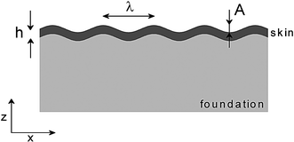 |
| | Fig. 1 Schematic illustrating the geometry of wrinkles in a thin skin (thickness h) residing on top of a thick elastic foundation. The wrinkles have a periodicity λ and amplitude A. | |
Eqn (2) states that the wavelength of the wrinkles depends only on the material properties of the skin and the foundation (their Poisson ratio and elastic modulus) and the thickness of the skin and is independent of the applied stress and strain (Δ). In order to gain appreciation for the magnitude of λ, in Fig. 2 we plot λ for various combinations of h and (Es/Ef). The wrinkle/buckle period is very small for small h and Es/Ef; it increases very rapidly with increasing both h and Es/Ef.
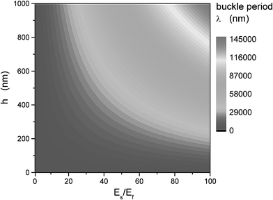 |
| | Fig. 2 Buckle period (λ) as a function of the skin thickness (h) and the ratio of the skin and foundation moduli (Es/Ef) evaluated using eqn (2). For simplicity, we consider the Poisson ratios of the skin and the foundation to be equal. | |
During the past few years, alternative ways of obtaining the expression for the wrinkle wavelength have been presented;18–21 these have been derived by balancing the bending energy of the skin, Us,B, and the stretching energy of the foundation, Uf,S. While the skin prefers to have wrinkles with a large wavelength, the foundation favors wrinkles with shorter wavelengths. A tradeoff between Us,B and Uf,S defines the optimum wavelength of the wrinkles. A particular breakthrough in the development of the theory of wrinkling has recently been achieved by Cerda and Mahadevan,20 who used the aforementioned concept to derive a general theory capable of describing wrinkling in virtually any geometry, not only flat sheets. Their main findings can be summarized in expressions for the wrinkle periodicity (λ) and amplitude (A):
| |  | (3) |
| |  | (4) |
In eqns (3) and (4), B represents the bending stiffness of the skin, K is the stiffness of the effective elastic foundation, and (Δ/w) is an imposed compressive strain; the concrete forms for K and Δ depend on a particular problem. Starting from the general expressions given by eqns (3) and (4), Cerda and Mahadevan discussed scaling laws for λ and A for several selected case studies. For example, they showed that for a flat sheet on an elastic foundation, eqn (3) reduced to λ
∼ (Es/Ef)1/3, in accord with the expression given by eqn (2).
3. Selected case studies
3.1 Back to human skin
Cerda and Mahadevan's theory also offers insight into mechanism of wrinkling in human skin. They showed that in this situation the general form of eqn (3) leads to:| |  | (5) |
where h and Es are the thickness and elastic modulus, respectively, of the epidermis and Hf and Ef are the thickness and elastic modulus, respectively, of the dermis. Given the fact that the dermis is typically ten times thicker than epidermis and considering that Es/Ef
≈ 1000, a value typical for human skin, one obtains λ
∼
Hf. This result reveals that wrinkles likely develop in places with an excess of skin. It also explains why it is unlikely to see wrinkles in eye lids, whose skin thickness is only ∼0.2 mm, hence about 10 times thinner than on other parts of the human body. We can also understand how cosmetic treatment via various skin moisturizers leads to reduction of wrinkling. Those products contain several ingredients (i.e., hydroxy acids) that help to remove old skin (i.e., damaged proteins), and supply new nutritional products that help to increase the delivery of collagen and elastin to the damaged areas in the epidermis. In some instances, the unhealthy top portion of skin can also be removed by so-called microdermabrasion,22 a process in which rough parts of the upper skin (stratum corneum) are buffed away using small crystals, e.g., aluminium oxide, sodium chloride or sodium bicarbonate. The body reacts to this treatment by replacing the removed skin with new and healthy cells. Both processes contribute to “softening” the skin and hence lowering Es. It has to be stressed that the story of skin wrinkling is actually a bit more complicated. As discussed by Cerda and Mahadevan, skin wrinkling also depends crucially on the geometric constrains imposed on system and the directions of the acting stresses.20 In regions where the skin drapes a bone, any tension or compression may lead to wrinkles. For example, such wrinkles readily develop around people's eyes as they age (so-called “ crow's feet”23).
3.2 Beyond the human skin
Skin wrinkling discussed above is just one of many examples of phenomena found in nature that involve formation of wrinkles or buckles. Consider for example some fruits, such as apples or plums, products that comprise a thin skin surrounding a soft interior made of water, proteins, lipids, carbohydrates, organic acids, fiber, and some minerals. When fruit dries, water is removed from the fruit, the volume of the soft part of the fruits decreases and as a result, the skin shrinks, giving rise to wrinkles. Prunes (i.e., dried plums) demonstrate this phenomenon nicely. Examples of wrinkles can also be found in the epidermal ridges, our fingerprints, which are known to start developing at the tenth week of pregnancy as small undulations at the interface between dermis and the bottom part of the epidermis (so-called basal layer). These so-called primary ridges continue to develop for about two more months.24,25 On a completely different length scale, in geology, hierarchical folding patterns resembling wrinkles26,27 are also well known, albeit still not completely understood. Table 1 summarizes a few selected examples of wrinkling; in all cases wrinkles form when a compressive force acts on a rigid skin that rests on a softer foundation. What is striking is the universality of the wrinkling phenomenon with length scales spanning many orders of magnitude.
Table 1 Examples of wrinkling of skins on softer elastic foundations. In each case we indicate the composition of the skin, foundation and the nature of the driving force
| Context |
Wavelength/m |
Skin |
Foundation |
Compressive force |
| Mountains |
103 |
Earth crust |
Earth mantle |
Tectonics |
| “Mosquito” wing failure |
10−1 |
Plywood |
Balsa |
Bending |
| Modern sandwich failure |
10−2 |
Glass fiber-reinforced epoxy |
Polyurethane foam |
Bending |
| Skin wrinkling |
10−3 |
Epidermis |
Dermis |
Skin stretching/compression |
| Fruits |
10−3 |
Skin |
Flesh |
Drying |
| Physically treated elastomers |
10−8–10−3 |
Metal or oxide film |
Elastomer |
Pre-stretching, stretching or thermal expansion |
Let us also mention a closely related phenomenon: Buckling of rods coupled to an elastic foundation. Perhaps the most notorious example here includes bucking on train rails that are subject to thermal expansion in hot summer months. It results from the mismatch between the thermal expansion of metallic rails and the soil, a less rapidly expanding foundation. The soil suppresses large wavelengths, so the wavelength of the buckle in the rails (a few times the width of an express train) will be determined by a compromise between the flexural rigidity of the track, and the mechanical properties of the soil. Similar phenomenon can be observed on a much smaller length scale in carbon nanotubes (CNT). Cox and coworkers28 have determined the flexural rigidity of CNT by studying their buckling behavior in epoxy matrices that served as elastic foundations. This work was based on much earlier work by Rosen et al.29 who studied a similar phenomenon for (much thicker) glass fibers embedded in epoxy. One final example we mention here comes from the field of biomechanics. Lordosis, an increased curvature of the normally curved lumbar spine, can also be viewed as an example of rod-buckling in an elastic foundation. Lordosis occurs in humans but more frequently in fish, where the chorda (or spine) is observed to have a local curvature. The wavelength of such a curved chorda is a compromise between the elastic properties of muscular tissue and the flexural rigidity of the chorda. In Table 2 we list selected example of rod buckling in elastic foundations.
Table 2 Examples of buckling of linear rods in combination with a soft elastic foundation. The underlying principles are the same as skin wrinkling, though the geometry is different
| Phenomenon |
Wavelength/m |
Fiber |
Foundation |
Compressive force |
| Nanotubes |
10−8 |
Carbon nanotube |
Epoxy matrix |
Shrinking matrix |
| Glass fiber bucking |
8 × 10⁻⁵ |
Glass fiber |
Epoxy matrix |
Temperature |
| Lordosis in fish |
10−2 |
Spine or chorda |
Muscular tissue |
Excess swimming activity |
| Buckling rails |
101 |
Rails |
Soil |
Temperature and thermal expansion mismatch |
3.3 Some outstanding issues in wrinkling/buckling
Although wrinkling in thin sheets has been studied for the past several decades, our understanding of this phenomenon is still far from complete. There are at least three major reasons for this. First, the morphology of buckles or wrinkles depends on the direction of the force acting on the foundation. For example, wrinkling in fruits occurs typically at random “in plane” because the foundation shrinks homogeneously. Multidirectional stresses acting on the sample and resulting in complex wrinkle morphologies are still rather difficult to fully comprehend, characterize, and ultimately utilize. In spite of that, models have been developed recently that aimed to understand “homogeneous” in-plane wrinkling and comparison with experimental work has been attempted.18 Mahadevan and Rica presented an elegant theory that explains the formation of Miura-ori patterns.30 By considering biaxial compression of thin rigid skin resting on top of an elastic foundation, the researchers demonstrated that patterns such as Miura-ori form in a two-step process, where buckles having a wavelength given by eqn (2) form initially without any in-plane orientation. Deformations of these buckles due to compression (along buckles) or extension (perpendicular to buckles) engrave the observed zigzag pattern orientation. The second major limitation stems from the fact that the simple theories of wrinkling or buckling, including the one briefly outlined earlier, assume that the skin is much stiffer than the foundation, which is assumed to be completely elastic. While this may be the case in some examples published in the literature (some of them will also be reviewed later in the text), in other instances, the skin is not always much stiffer than the foundation layer. Moreover, in many instances the foundation itself is viscoelastic rather than elastic. The third caveat is related to the internal structure of the buckling material. So far, we have only considered buckling in bilayer systems comprising a thin and stiff sheet lying on top of the soft thick foundation; the interface between the two layers without any initial strain was considered to be completely flat. In real situations, the structure is likely much more complex. For instance, it is known that the interface between the epidermis and dermis in human skin is not completely flat and smooth.7 Indeed, recent computer simulation work suggests that a three-layer model is needed in order to adequately explain clinical observations of skin wrinkling.7
In the sections that follow we will summarize several recent experiments pertaining to wrinkling of stiff skins attached to elastic and viscoelastic foundations. The skins were either formed by physically densifying the topmost part of the substrate by some physical treatment (plasma, ultraviolet/ozone treatment) or by depositing a thin layer of metal. The examples we will discuss will also illustrate how the wrinkle/buckle morphologies on the substrate can be tailored by using: (1) 3D topographical structures present on the foundation prior to the deposition of skin, (2) mechanical deformation of wrinkled substrates, and (3) guiding the buckle orientation by pressing a non-planar mold against the skin during the buckle formation. Finally, we outline examples of a few applications, whose functionality is derived from the presence of wrinkles/buckles in sheets.
3.4 Wrinkling in rigid sheets on elastic foundations
We start by considering wrinkles of rigid sheets attached to elastic foundations. Virtually all work reported to date utilized a two-layer system comprising a thick foundation made of poly(dimethylsiloxane) (PDMS), a highly elastic material having the Young's modulus of ∼1 MPa,31 decorated with a thin rigid layer made of either metal or a silicon oxide. Bowden and coworkers reported several strategies of forming wrinkles/buckles on top of PDMS. One of them32 involved increasing the volume of the PDMS block by heating, exposing it to oxygen plasma for controlled periods of time, and finally cooling the sample down to room temperature. The plasma oxidation converted the topmost part of the PDMS into a silica-like layer. The wavelength and the amplitude of the wrinkles increased with increasing plasma treatment time (see Fig. 3). This behavior was caused by increasing the thickness and/or the Young's modulus of the silica-like layer. Bowden and coworkers also reported that the buckle wavelength (λ) was independent of the magnitude of the compressive stress, regulated by pre-heating the PDMS block to various temperatures. These findings are in accord with the predictions of eqn (2), which indicates that λ is independent of Δ. In the same paper, the researchers showed that while wrinkles were generally disordered in plane when formed on a flat PDMS sheet (see Fig. 4a), they oriented when generated on PDMS substrates comprising 3D posts. Specifically, at the posts in PDMS substrate, the stress perpendicular to the post was relieved by expansion, causing the wrinkles to orient in the direction perpendicular to the post (see Fig. 4b). Further tailoring of the wrinkle characteristics was achieved by varying the distance between the posts in the PDMS foundation. In a subsequent paper, Chua and coworkers reported on the formation of complex surface structures with tailored sizes created by exposing PDMS substrates with holes (rather than protrusions) to oxygen plasma.33 These morphologies were associated with the disruption of equibiaxial stresses (present in planar PDMS samples) during the plasma treatment of PDMS (see Fig. 5).
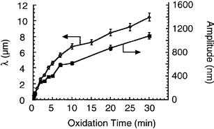 |
| | Fig. 3 The wavelength (λ) and amplitude (A) of wrinkles as a function of the plasma oxidation time of poly(dimethylsiloxane) from ref. 32. | |
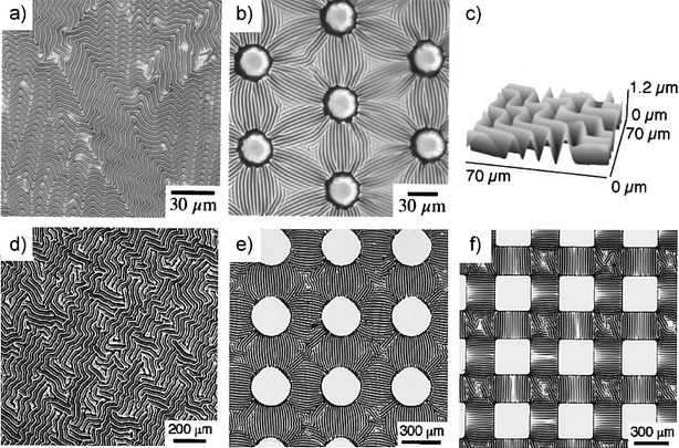 |
| | Fig. 4 Optical micrographs of buckled surfaces prepared by plasma oxidation of heated poly(dimethylsiloxane) (PDMS) sheet comprising (a) homogeneous PDMS layer and (b) PDMS substrate with posts (height: 5 µm high, diameter: 30 µm) separated by 70 µm. The buckles were formed upon cooling the sample to room temperature. (c) Scanning force microscopy image of disordered buckling waves. Optical micrographs of patterns formed when a thin layer of gold was deposited onto warm PDMS and the sample was cooled to room temperature. (d) Disordered patterns, (e) circles (radius: 150 µm), and (f) flat squares (side: 300 µm) elevated by 10–20 µm relative to the surface showed ordered patterns of waves on the recessed regions and no buckling on the plateaus from refs 32 and 35. | |
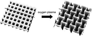 |
| | Fig. 5 Scanning force microscopy images (20 × 20 µm2) of a poly(dimethylsiloxane) substrate with relief patterns prior to and after oxygen plasma modification from ref. 33. | |
Several groups studied the formation of buckled structures on elastomeric foundations by vapor deposition of thin metal films onto thick PDMS substrates. One of the earliest experiments was reported by Martin and coworkers, who observed that after evaporating aluminium onto a liquid nitrogen-cooled PDMS substrate and raising the temperature, the sample surface was decorated with fine metallic folds.34 While no specific comments were provided in the original paper onto this phenomenon, one may speculate that the topological pattern observed by Martin and coworkers was related to the formation of wrinkled surface due to the expansion of PDMS when it was heated up back to the room temperature. Bowden and coworkers prepared buckles by depositing thin layers of gold onto thick PDMS at elevated temperatures.35 Subsequent cooling of the substrate developed compressive stresses in the specimens that were relieved via the formation of buckles having periodicity of 20–50 µm (see Fig. 4). While wrinkles generated on flat PDMS sheets were organized randomly in plane (see Fig. 4d), they formed oriented morphologies extending over large areas (Fig. 4e and 4f) when deposited on PDMS substrates containing 3D protrusions. Bowden et al. also observed the formation of a herringbone buckling pattern on samples formed by evaporating a thin layer of gold onto a thick PDMS foundation pre-patterned with a circular depression (see Fig. 6). Chen and Hutchinson have recently provided detailed analysis of the mechanism leading to the herringbone patterns.36 They have shown that such a pattern is associated with the lowest average elastic energy of the skin/foundation bilayer for skins stressed well beyond the critical stress. The researchers were, however, unable to address the mechanism leading to the formation of such a pattern. Huck and coworkers extended the work of Bowden et al. by first stiffening selected areas on the substrate via crosslinking and subsequent metal deposition at elevated temperatures.37 After cooling the sample, the surface exhibited a complex arrangement of buckled structures. Specifically, while the buckles were found to be aligned perpendicular to the boundaries between the strips on pre-crosslinked areas on the sample, they oriented parallel to the boundaries on the “bare” PDMS loci (see Fig. 7). Another very recent example of modulating wrinkling patterns in thin sheets has been presented by Ohzono and coworkers, who deposited thin films of platinum onto hexagonally organized arrays of holes in PDMS38 and showed that the directional order of buckles was induced by the underlying substrate when the periodicity of the substrate pattern matched the intrinsic wavelength of the wrinkles (see Fig. 8). Ozhono and coworkers also studied response of wrinkles to applied stress.39 They first evaporated a thin film of platinum onto a thick PDMS slab, which resulted in a disordered array of wrinkles (see Fig. 9). By applying a small uniaxial stress to the samples, they showed that the wrinkles aligned perpendicularly to the direction of the stress; only 7% strain was needed to achieve almost perfect wrinkle alignment. Ozhono et al. determined that ordered domains of wrinkles grew via rearrangement of the stripe orientation of neighbors, merged with one another, and finally covered a large area on the surface. Upon releasing the stress, the wrinkles returned to their original disordered morphology, albeit with a small hysteresis (see Fig. 9). In a subsequent publication, Ohzono et al. were able to reproduce their earlier experimental observations using a computer simulation models.40,41 Their study confirmed that the strong memory of the initial wrinkling pattern was responsible for the recovery of the sample to the initial morphology after the strain, which was used to align the wrinkles, was removed.
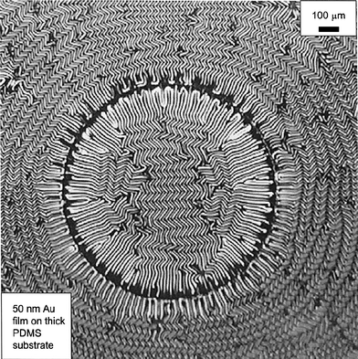 |
| | Fig. 6 Gold film deposited onto poly(dimethylsiloxane) substrate, which has been pre-patterned with a circular depression. The herringbone pattern is present both in the center of the circular spot and outside the edges of the spot from ref. 36. | |
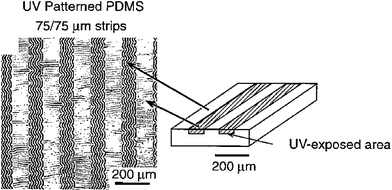 |
| | Fig. 7 Alignment of buckles in thin films on poly(dimethylsiloxane) patterned onto regions differing in Young's modulus and coefficient of thermal expansion from ref. 37. | |
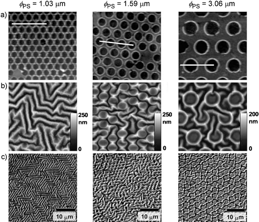 |
| | Fig. 8 (a) Scanning force microscopy (SFM) images (10 × 10 µm2) of the lithographic pattern produced by oxygen plasma treatment of poly(dimethylsiloxane) (PDMS) after removing polystyrene (PS) latex microspheres. (a) SFM images (10 × 10 µm2) and (c) optical microscopy images of wrinkle patterns coupled to lithographically patterned substrates. The left, middle, and right columns indicate the results for PS spheres having diameters (ϕ) of 1.03, 1.59 and 3.06 µm, respectively from ref. 38. | |
 |
| | Fig. 9 Scanning force microscopy images (11 × 11 µm2) of wrinkled samples prepared by evaporating a thin layer of platinum onto a thick poly(dimethylsiloxane) substrate. The images illustrate the rearrangement of the original disordered wrinkling pattern upon imposing a small uniaxial stress (the corresponding strains are indicated below each image) and a subsequent return to the original pattern upon stress removal from ref. 39. | |
In all the examples discussed thus far, the strain imposed on the PDMS foundation was relatively small, only a few percent. A question may arise: What will the buckled surface look like if much larger strains (and thus much larger compressive stresses) are involved? In addition, the oxygen plasma treatment of PDMS typically leads to silicon-oxide-like layers, whose thicknesses are on the order of a few tens to several hundreds of nanometres.42 Based on eqn (2), producing thinner layers should lead to the formation of wrinkles with periodicities smaller than a few microns. Efimenko and coworkers recently reported on fabrication of wrinkles by uniaxially stretching PDMS network sheets (thickness ∼0.5 mm) in a custom-designed stretching apparatus43 and exposing them to ultraviolet/ozone (UVO) radiation for extended periods of time (30–60 min).44 Previous studies established that the UVO treatment of PDMS converts the first ∼5 nm of the PDMS surface into a stiff skin,45 whose density is approximately half that of silica.46 Optical microscopy and scanning force microscopy (SFM) experiments confirmed that the surfaces were originally flat in the presence of strain. After the UVO treatment, the strain was removed from the specimen and the skin buckled perpendicularly to the direction of the strain. A detailed analysis of the buckled surface with SFM and profilometry uncovered the presence of hierarchical buckling patterns (see Fig. 10). Buckles with smaller wavelengths (and amplitude) rested parallel to and within larger buckles, forming a nested structure. At least five distinct buckle generations (G) were detected with their wavelengths ranging from tens of nanometres to a fraction of a millimeter. Efimenko and coworkers also explained the mechanism leading to such hierarchical buckling patterns. Using experimentally measured values of Es/Ef and h, they established that upon releasing the strain from the sample, the first generation buckles (G1) formed first. The composite of the wrinkled skin and the stretched substrate led to the formation of an “effective skin” that was thicker and much stiffer than the original skin. Further release of the applied strain led to additional effective compression; the composite skin buckled on a much larger length scale. The formation of higher generation buckles continued until the strain was completely removed from the substrate hence creating a hierarchical buckled pattern, where each buckle generation was a scaled-up version of the primary buckle. The self-similarity of the buckles was confirmed by utilizing the scaling prediction given by eqn (4). By plotting the scaled experimental amplitude (A/Δ1/2) as a function of λ all data collapsed roughly on a single master curve (see Fig. 11).
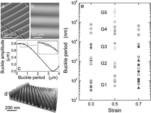 |
| | Fig. 10 Characterization of the nested hierarchy of buckles. (a) Scanning electron microscopy image of a buckle on poly(dimethylsiloxane) substrate (covered with a ∼4 nm thick layer of platinum) revealing the G4 generation of buckles. (b) Optical microscopy image in the transmission mode of G3 and G4 generations of buckles. (c) Topography profile collected with profilometry on G2 (inset) and G3 (main figure) generations of buckles. (d) Scanning force microscopy image revealing the structure of G1 buckles. (e) Buckle period as a function of the strain imposed on the samples before the ultraviolet/ozone treatment lasting for 30 (squares), 60 (circles), and 90 (up-triangles) minutes as measured by scanning force microscopy (filled symbols) and profilometry (open symbols) from ref. 44. | |
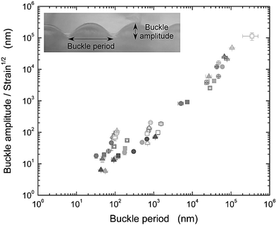 |
| | Fig. 11 Ratio of the buckle amplitude to the square root of the strain plotted as a function of the buckle period on a log–log plot. The symbols are the same as in Fig. 10. The data collapse onto a master line, in accord with eqn (4) from ref. 44. | |
3.5 Wrinkling in rigid sheets on viscoelastic foundations
So far our discussion has concentrated on wrinkling of rigid skins lying on top of elastic foundations. However, wrinkling can also occur in more complex systems, involving an elastic film on a viscous layer,47–49 a solid film residing on top of a liquid base,50 and others. In situations like these, the system can no longer be modeled using eqn (2) and a more complicated set of expressions has to be invoked, which may also contain time-dependent properties (e.g., modeling the characteristics of the viscous layer),47–49 and interaction energies acting among the layers present in the system,50 thus leading to complex phase diagrams. Dalnoki-Veress and coworkers reported on buckling that occurs in three layer systems comprising polystyrene (PS) sheets with various thicknesses sandwiched between two thin SiOx layers (thicknesses ranging from ∼18 to ∼30 nm).51 The researchers showed that a simple model that invoked only interactions acting at the SiOx–air interfaces, and included elastic modulus of the capping layer and thicknesses of the PS and SiOx layers, was capable of describing the experimentally observed wrinkle wavelength. In order to test the effect of the dispersion forces in driving the wrinkle morphology, Dalnoki-Veress et al. also performed similar experiments with other symmetric three-layer systems, including SiOx–PMMA–SiOx, Au–PS–Au, PS–PI–PS, and asymmetric systems, including Au–PS–SiOx, SiOx–PS–(Si–H), PS–PI–(Si–H), where PMMA is poly(methylmethacrylate), PI is polyisoprene, and Si–H is hydrogen-terminated silicon. All systems exhibited the same wrinkled morphology upon annealing.
In a series of papers, Lee and coworkers reported on a systematic study of wrinkling in systems comprising thin metal skins residing on top of viscoelastic foundations.52–54 The researchers thermally deposited aluminium films with various thicknesses onto PS substrates. Annealing the samples above the PS glass transition temperature (Tg
≈ 105 °C), followed by cooling the specimens down to room temperature led to the formation of wrinkles (see Fig. 12a). The authors also showed that the directionality of the wrinkles can be adjusted by placing a patterned PDMS mold on top of the metal/PS bilayer. The strong conformal contact between the PDMS mold and the metal surface makes the edges of the pattern act as nodes, which dictate waves within the period of the mold pattern (see Fig. 12b and 12c). The surface shapes were found to depend on the shape of the PDMS mold and the “intrinsic” wrinkle wavelength; the latter was obtained by balancing the bending energy of the metal layer and the deformation energy of the PS substrate.52 In subsequent work, Yoo and Lee pointed out the similarity between the kinetics of wrinkle development in metal/polymer bilayers and that observed in spinodal decomposition in liquids.55 They argued that because of the slow kinetics of stress-driven wrinkling in thin films, early stages of instability can be captured; this is in contrast to typical spinodal decomposition kinetics in liquid systems, whose early stages are rather hard to monitor because they take place very rapidly. In the same paper, Yoo and Lee reported on a two-stage process of wrinkle formation where upon completely covering the surface with wrinkles having a period λ1, a new wrinkling wave appeared underneath the wrinkled surface; the wrinkle periodicity of the second wave λ2 was larger than λ1. This behavior thus closely resembles the features reported in ref. 44. In their subsequent work, Yoo and collaborators addressed the effect of the dispersion forces acting on the bilayer system and the role of relaxation in the polymer film.56 They reported that while the dispersion forces do not play a significant role in wrinkling, relaxation in the polymer film appreciably affects the wrinkle pattern; the wrinkles change their topology from continuous wavy patterns to discrete worm-like islands.
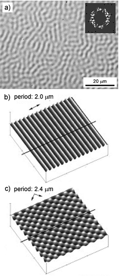 |
| | Fig. 12 (a) Optical micrograph of wrinkles generated on 400 nm thick polystyrene (PS) film supported on a flat silicon wafer capped with 60 nm thick layer of aluminium after annealing at 120 °C for 2 h. The inset shows the fast Fourier transform of the wrinkling wave. (b) and (c) Ordered wrinkling structures formed by placing a poly(dimethylsiloxane) (PDMS) mold onto aluminium/PS bilayers. The three-dimensional relief on the PDMS stamp governs the direction of the wrinkling waves. By applying a PDMS stamp comprising lines of equal width and spacing (2 µm) the wrinkles order parallel (b), by using a cylindrical dot PDMS mold (period 2 µm) the wrinkles break into symmetric 3D protrusions (c) from ref. 52. | |
In a related work, Okayasu and coworkers explored the formation of wrinkled patterns on thin films comprising aluminium layers deposited on PS substrates after heating the system to temperatures above the glass transition of PS (∼80–100 °C, depending on the molecular weight).57 The researchers reported that the minimum annealing temperature required for the buckling patterns to form depended on the thicknesses of aluminium capping layer (it increased slightly with increasing aluminium layer thickness), PS film thickness (it increased with decreasing PS film thickness), and PS molecular weight. Okayasu et al explained the formation of buckling patterns by invoking a simple model based on lateral stresses associated with the mismatch of the thermal expansion coefficients of the two layers. Very recently, Ozhono and Shimomura reported a study aiming at understanding how winkles formed on platinum layer-covered PDMS substrates respond to additional strain imposed on the wrinkled substrates.58 Their study uncovered interesting features of the wrinkled topologies associated with dynamical control of the surface topographical patterns.
4. What are wrinkles good for, anyway?
Wrinkles always exist in rather extended numbers of replicas organized in periodic structures. To this end, wrinkles are not very unique as they constitute only a small subset of spontaneously formed periodic patterns and wavelets present in nature.59–61 The periodic nature of wrinkles/buckles has recently led to the development of interesting applications. These include: diffraction gratings, pressure sensors, substrates to control the direction of cell growth, substrates to monitor the stress a cell places on a surface, stamps for microcontact printing, masks for lithography, channels with microstructured walls for microfluidic devices, or functional coatings. We thus conclude this paper with a brief overview of several applications that utilize wrinkling.
Shapeable materials have long been considered as potential candidates for creating sensor skins, electro-textiles, conformal displays and electronic muscles. The flexibility of the elastomeric foundation provides the necessary deformable substrate required in some of the aforementioned applications. Lacour and coworkers reported on the formation of stretchable gold interconnects based on buckles in elastomeric substrates.62–64 The researchers evaporated strips of metal comprising a thin layer of chromium followed by a thicker layer of gold via a shadow mask on PDMS substrate. This procedure led to the formation of buckles comprising alternating gold/PDMS strips. Conductance measurements performed as a function of the tensile strain (applied in the direction perpendicular to the buckles) on the sample revealed that the gold strips remained conductive up to 22% of strain. Cycling between stretched and unstretched states did not lead to any appreciable changes in conductivity. In a subsequent study, Wagner extended the previous work by evaporating gold electrodes onto PDMS films pre-stretched uniaxially by 15%.65 Electrical resistance measurements revealed that the gold strips remained conductive on samples stretched up to 28% of their unstretched length. Watanabe and coworkers66 prepared a wrinkled electrode via in situ deposition of polypyrrole onto uniaxially stretched polyurethane elastomer films. Electrode wrinkles formed upon releasing the strain from the film. Conductivity experiments revealed that the wrinkles enabled the electrode to elongate without appreciable decrease in conductivity. These experiments thus suggested that when properly engineered, systems comprising thin metal films or glassy conductive polymers residing on top of elastomeric substrates could be used as interconnects in skin-like flexible electronic circuits.
A very elegant application of wrinkling of rigid films on elastomeric substrates has recently been developed by researchers at the US National Institute of Standards and Technology.67 Stafford and coworkers introduced a new measurement technique coined as strain-induced elastic buckling instability for mechanical measurements (SIEBIMM), which utilizes wrinkling in thin films to determine the modulus of the skin material. By placing a thin film of a given thickness (h) and unknown modulus (Es) on top of an elastomeric foundation of known modulus (Ef) and by measuring the wrinkle wavelength (λ) upon stretching the bilayer beyond the critical strain, Es can be determined from a rearranged form of eqn (2):
| |  | (6) |
Stafford et al. also demonstrated that SEIBIMM can be utilized for quantitative screening of combinatorial libraries with spatially varying properties of the skin layer. Fig. 13a depicts an optical micrograph of a sample comprising a PS film with a gradient in thickness, h, ranging from 140 to 280 nm, which resides on top of a 2 mm thick PDMS sheet. Upon applying tensile strain to the sample, buckles developed that were oriented parallel to the direction of strain; the buckle periodicity increased with increasing thickness of the PS film (see Fig. 13a). Precise determination of the buckle periodicity was accomplished by utilizing in situ small-angle scattering of a low-power HeNe laser. The data in Fig. 13b illustrate that λ scales linearly with h, as predicted by eqn (2). The PS modulus determined using eqn (6) was found to be constant over the entire range of PS film thickness and in agreement with reported bulk values. In the same publication, Stafford and coworkers illustrated the versatility of SIEBIMM by determining the modulus of plasticized PS films and modulus of porous organosilicate film. These few examples illustrate that SIEBIMM may become a very useful tool for rapid, systematic, and quantitative screening of the mechanical properties of thin films.
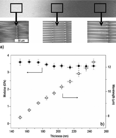 |
| | Fig. 13 (a) Optical micrograph of a polystyrene film thickness gradient (thickness: 140 to 280 nm) on silicon wafer. Greyscale insets show optical micrographs of the film after transfer to poly(dimethylsiloxane) and application of strain to induce buckling. The doubling of the film thickness from left to right results in a doubling of the buckling period. (b) Modulus versus thickness for a flow-coated thickness gradient sample. The modulus (filled circles) remains largely constant (3.4 ± 0.1 GPa) over this thickness range from ref. 67. | |
Early on, researches realized that the periodic nature of wrinkles can be exploited in a range of optical devices, most notably optical gratings. Bowden and coworkers fabricated a wrinkle-based diffraction grating; the angular displacement of the first order diffraction spot on the grating was found to be linearly proportional to the strain applied on the PDMS before plasma oxidation.32 A very detailed account of wrinkle application in optical grating technology has recently been presented by Harrison and coworkers.68 Using the PS/PDMS bilayer used in their previous work discussed above,67 Harrison et al. demonstrated that the intensity of the diffraction peaks in small angle light scattering experiments can be tuned by three orders of magnitude while varying the strain imposed on the specimen by only 10%.
Surfaces that possess topological features have long been recognized as potential templates that may assist assembly of various objects. For instance, a large body of literature exists that demonstrates undoubtedly the effect of surface topography on cell morphology on surfaces.69 It has been shown that anisotropic topographic features on the surface induce cells to align and eventually move along the surface anisotropies, so-called contact guidance.70 Previous examples illustrated various techniques that enable fabrication of wrinkled surfaces with controlled wrinkle orientation, size, depth, and chemistry. These features would make wrinkled/buckled topologies valuable candidates for material assembly. Efimenko and coworkers recently discussed one possible application that directly utilizes the hierarchical nature of the buckled structures: the separation of a mixture containing particles of various sizes.44 An aqueous suspension of particles with three different sizes was pumped past the buckled surface (direction perpendicular to the buckles) at a constant flow rate; the particles separated on the substrate with the bigger particle residing predominantly in the valleys of buckles with larger periodicities, and smaller particle aligning along smaller buckles.44 The mechanism of wrinkle formation outlined in ref. 44 has recently been utilized to align silica particles in situ.71 PDMS sheet was stretched uniaxially and exposed to UVO treatment. The surface of the pre-stretched UVO-modified PDMS film was wetted with a small amount of aqueous solution containing silica particles (diameter ∼80 µm). Upon slowly removing the strain from the sample, wrinkles formed orthogonally to the strain direction. The wrinkles, in turn, forced the particles to align into long particle chains (see Fig. 14).
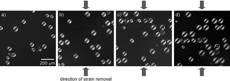 |
| | Fig. 14 Ordering of silica particles in 2D geometries via in situ formation of buckles. Poly(dimethylsiloxane) substrates were stretched uniaxially, exposed to ultraviolet/ozone treatment for 90 min. Aqueous solution of silica particles (diameter ∼80 µm) was placed on the pre-stretched substrate (a) and the strain was slowly removed from the specimen. The particles started to orient in the direction perpendicular to the removed strain (b–d). The buckles generated in the substrate are visible in part (d) K. Efimenko, J. Genzer, unpublished results. | |
As a final example, we discuss perhaps a slightly unusual application of wrinkled substrates—an efficient foul-release marine coating. Marine biofouling is a serious and complex problem resulting in losses of operating efficiency of ships.72 Current coating technologies derived from copper- and tin-based compounds are being banned because of detrimental effects on the marine environment.73 Hence there is need for developing efficient marine coatings that would possess no ecological concern. In addition to various chemical approaches, surface topography has also been shown to be important for mechanical defense against macrofouling on a larger scale, which may be hindered by certain surface structures, such as spicules.74 For instance, Hoipkemeirer-Wilson and coworkers reported that topographically corrugated surfaces are capable of reducing biofouling.75 The degree to which fouling was reduced was found to depend on the dimensions of the geometrical protrusions as well as the chemistry of the surfaces. Because biofouling includes a very diverse range of various species, whose sizes span several orders of magnitude, one single topographical pattern will not likely perform as an effective antifouling surface. Rather, surface corrugations having multiple length scales acting in parallel should be used in designing a very effective antifouling surface. The hierarchically wrinkled (H-wrinkled) topographies described earlier in this review44 may represent a convenient platform for designing such surfaces. In order to test this hypothesis, Efimenko et al. prepared a series of H-wrinkled substrates decorated with a thin semifluorinated monolayer and tested their fouling properties by immersing them into seawater for controlled periods of time.76 Pictures of samples taken immediately after removing the specimens from the seawater indicated the presence of a considerable amount of adsorbed biomass on samples with flat geometries (see Fig. 15, left panel). Significantly smaller fouling was seen on H-wrinkled specimens (see Fig. 15, right panel). The difference between the two sample categories became even more noticeable after washing the specimens with a stream of water. While the flat PDMS samples remained fouled rather considerably, the surfaces of the H-wrinkled coatings cleaned up almost completely. While more work still needs to be done to fully understand this phenomenon, the initial observations suggest that the H-wrinkled coatings may represent a new and promising platform for fabricating efficient foul-release marine coatings.
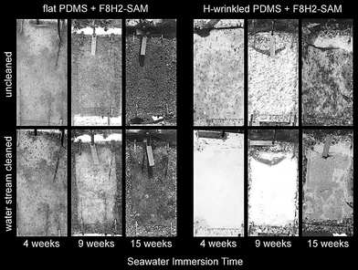 |
| | Fig. 15 Images of marine coatings comprising flat poly(dimethylsiloxane) (PDMS) (left panel) and hierarchically wrinkled PDMS (right panel) sheets covered with a self-assembled monolayer made of 1H,1H,2H,2H-perfluorodecyltrichlorosilane (F8H2-SAM) after immersion in seawater (Wilmington, NC, April–August 2005) for various times. The upper row shows samples immediately after the removal from the seawater, the bottom row depicts specimens after washing with a water stream. K. Efimenko, J. Genzer, unpublished results. | |
Let us for the last time return back to wrinkles in human skins. Why do skin wrinkles make so many people unhappy? The appearance of wrinkles in human skin is commonly perceived as a sign of ageing. So it is the aesthetic value of wrinkles that causes so much attention. However, the visual effects caused by wrinkles may not always be so troublesome. In fact, one may think of several examples where wrinkles are used to visualize various physical phenomena. For instance, wrinkles generated by a cell crawling on a soft substrate (see Fig. 16a and b) have been used as a quantitative means of envisaging forces generated during cell locomotion.77,78 Shear-induced wrinkling of polymerized vesicles (see Fig. 16c and d)79 can be used to determine the bending stiffness of the membrane, a critical parameter in determining the robustness of these vesicles as they move through capillaries. Yet another example involves chemothermomechanical wrinkling patterns in thin metal catalysts (see Fig. 16e and f), which are caused by coupling between catalytic and thermal action during surface chemical reaction.80 Based on these few examples, one may conclude that visual appearance of wrinkles is not always that bad; in many instances wrinkling/buckling can reveal a great deal of interesting and important information about the system behavior. After all, consider also the Chinese Shar-Pei (see Fig. 16g)—although heavily wrinkled, the Shar-Pei is one of the most beloved pets.
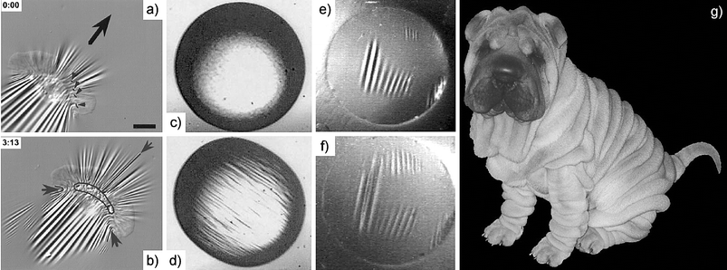 |
| | Fig. 16 (a) and (b) Deformation of substrates (silicon rubber, whose surface layer was vulcanized by heat77) by keratocyte cells at two time intervals (time in seconds shown left upper corner of each image). The large arrow indicates the direction of the cell movement. Bar = 10 µm. (c) and (d) Deformation of polysiloxane microcapsule (radius = 343 µm) at a shear rate of 0 s−1 (c) and 18 s−1 (d) from ref. 79. (e) and (f) Diffuse light image of a thin (∼200 nm) platinum catalyst under weak laser excitation in the absence of reactive gases (e), and after rapid exchange of reactive gases (f) from ref. 80. (g) The Chinese Shar-Pei, the dog that is “too small to fit properly into its fur”. | |
6. Conclusions
The aim of this review was to provide only a brief summary of an interesting material phenomenon: wrinkling or buckling in sheets. We note that we have completely omitted other important mechanical instabilities occurring in sheets, such as folding, crumpling, or tearing.81–87 We hope that this brief and broad overview demonstrated that there is a plethora of interesting science and many applications that rely on wrinkling or buckling in thin sheets. While in some cases wrinkling may not always be appreciated (i.e., wrinkling in human skin), in other situations wrinkles can help to study and comprehend various physical phenomena (i.e., system instabilities), guide assembly of materials, fabrication of various functional devices (i.e., optical gratings, stamps for microcontact printing, channels for microfluidic devices), and in other instances also assist in measuring material properties that would otherwise be very hard to establish (i.e., modulus in thin films). It is our hope that this brief account will stimulate additional exciting work on wrinkles and buckles. In fact, here is a little experiment you, the reader, can do immediately. Pour some scalded milk (milk heated almost to boiling) or cocoa into a cup and watch the milk-skin (or cocoa-skin) develop on the surface.§ As you blow cold air into the cup, you will see wrinkles dancing on top of the cooled liquid. Maybe watching these winkles tangoing will bring about some new exciting “buckling inspiration”…
Acknowledgements
The authors thank Professor L. Mahadevan (Harvard University) for many fruitful discussions. We also thank Dr Rajendra R. Bhat (NC State University) for reading the manuscript and providing useful comments and suggestions. The work at NC State University has been supported by the grants provided by the Office of Naval Research and the National Science Foundation.
References
-
Y. Lamir, Skin Mechanics, in Handbook of Bioengineering, ed. R. Skalak, McGraw-Hill, New York, 1987 Search PubMed.
- C. Escoffier, J. de Rigal and A. Rochefort, Age related mechanical properties of human skin, J. Invest. Dermatol., 1980, 93, 353–357.
- Y. Takema, Y. Yorimoto and M. Kawai, Are related changes in the elastic properties and thickness of human facial skin, Br. J. Dermatol., 1994, 131, 641–648 CAS.
-
D. Battise, R. Bazin and T. Baldeweck, Age Related Changes in the Folding Capacity of the Skin, European Academy of Dermatology and Venereology, Geneva, 2000, pp. 11–15 Search PubMed.
-
M. Viaud and H. Yahia, Facial animation of wrinkles, Third Workshop on Animation, Eurographics, Cambridge, Springer–Verlag, Heidelberg, 1992 Search PubMed.
- L. Boissieuzm, G. Kiss, N. Magnenat Thalmann and P. Karla, Simulation of skin ageing and wrinkles with cosmetics insight, Computer Animation & Simulation, 2000, 15–27 Search PubMed.
- N. Magnenat Thalmann, P. Karla, J. L. Lévêque, R. Bazin, D. Batisse and B. Quarleux, A computational skin model: Folds and wrinkles formation, IEEE Trans. Inf. Technol. Biomed., 2002, 6, 317–323 CrossRef.
-
Handbook of Non-Invasive Methods and the Skin, ed. J. Serup and G.B.E. Gemec, CRC Press, Boca Raton, FL, 1995 Search PubMed.
- B. F. van Duzee, The influence of water content, chemical treatment and temperature on the rheological properties of stratum corneum, J. Invest. Dermatol., 1978, 71, 40–44 CrossRef.
-
http://www.nasm.si.edu/research/aero/aircraft/dehavilland_mosquito.htm
.
- B. Imhof, Modern sandwich core materials offer new attractive design possibilities, Aircraft Eng. Aerosp. Technol., 1997, 69, 332–333 Search PubMed.
- M. A. Biot, Folding instability of a layered viscoelastic medium under compression, Proc. R. Soc. London, Ser. A, 1957, 242, 444–454 Search PubMed.
-
M. A. Biot, Mechanics of Incremental Deformation, Wiley, New York, 1965 Search PubMed.
-
L. D. Landau and E. M. Lifshitz, Elasticity Theory, Nauka, Moscow, 1965 Search PubMed.
-
S. Timoshenko, Theory of Elastic Stability, McGraw-Hill, New York, 1988 Search PubMed.
-
D. O. Bush and B. O. Almroth, Buckling of Bars, Plates and Shells, McGraw-Hill, New York, 1975 Search PubMed.
-
H. G. Allen, Analysis and Design of Structural Sandwich Panels, Pergamon, New York, 1969 Search PubMed.
- J. Groenewold, Wrinkling of plates couples with soft elastic media, Physica A, 2001, 298, 32–45 CrossRef.
- E. Cerda, K. Ravi-Chandar and L. Mahadevan, Wrinkling of an elastic sheet under tension, Nature, 2002, 419, 579–598 CrossRef CAS.
- E. Cerda and L. Mahadevan, Geometry and physics of wrinkling, Phys. Rev. Lett., 2003, 90, Art. No. 074302.
- N. Uchida, Orientational order in buckling elastic membranes, Physica D, 2005, 205, 267–274 CrossRef.
- M. S. Freeman, Microdermabrasion, Facial Plast. Surg. Clin. North Am., 2001, 9, 257–266 Search PubMed.
- D. Drollette, New wrinkle on fighting crow's feet, Phys. Rev. Focus, 2003, 11, story 7 Search PubMed.
- W. J. Babler, Embryologic Development of Epidermal Ridges and Their Configurations, Birth Defects: Orig. Art. Ser., 1991, 27, 95–112 Search PubMed.
- M. Kücken and A. C. Newell, A model for fingerprint formation, Europhys. Lett., 2004, 68, 141–146 CrossRef.
-
N. J. Price and J. W. Cosgrove, Analysis of Geological Structures, Cambridge University Press, Cambridge, 1990 Search PubMed.
- P. J. Huddleston and L. Lan, Information from fold shapes, J. Struct. Geol., 1993, 15, 253–264 CrossRef.
- O. Lourie, D. M. Cox and H. D. Wagner, Buckling and Collapse of Embedded Carbon Nanotubes, Phys. Rev. Lett., 1998, 81, 1638–1641 CrossRef CAS.
-
B. W. Rosen and N. F. Dow, Mechanics of failure of fibrous composites, in Fracture, An Advanced Treatise, ed. H. Liebowitz, Academic Press, New York, 1972, vol. 7, ch. 8, pp. 612–672 Search PubMed.
- L. Mahadevan and S. Rica, Self-organized origami, Science, 2005, 307, 1740 CrossRef CAS and supplemental online material.
- R. C. Hedden, H. Saxena and C. Cohen, Mechanical properties and swelling behavior of end-linked poly(diethylsiloxane) networks, Macromolecules, 2000, 33, 8676–8684 CrossRef CAS.
- N. Bowden, W. T. S. Huck, K. E. Paul and G. M. Whitesides, The controlled formation of ordered, sinusoidal structures by plasma oxidation of an elastomeric polymer, Appl. Phys. Lett., 1999, 75, 2557–2559 CrossRef CAS.
- D. B. H. Chua, H. T. Ng and S. F. Y. Li, Spontaneous formation of complex and ordered structures on oxygen-plasma-treated elastomeric polydimethylsiloxane, Appl. Phys. Lett., 2000, 76, 721–723 CrossRef CAS.
- G. C. Martin, T. T. Su, I. H. Loh, E. Balizer, S. T. Kowel and P. Kornreich, The metallization of silicone polymers in the rubbery and the glassy state, J. Appl. Phys., 1982, 53, 797–799 CrossRef CAS.
- N. Bowden, S. Brittain, A. G. Evans, J. W. Hutchinson and G. M. Whitesides, Spontaneous formation of ordered structures in thin films of metals supported on an elastomeric polymer, Nature, 1998, 393, 146–149 CrossRef CAS.
- X. Chen and J. W. Hutchinson, Herringbone buckling patterns of compressed thin films on compliant substrates, J. Appl. Mech., Trans. ASME, 2004, 71, 597–603 Search PubMed.
- W. T. S. Huck, N. Bowden, P. Onck, T. Pardoen, J. W. Hutchinson and G. M. Whitesides, Ordering of spontaneously formed buckles on planar surfaces, Langmuir, 2000, 16, 3497–3501 CrossRef CAS.
- T. Ohzono, S. I. Matsushita and M. Shimomura, Coupling of wrinkle patterns to microsphere-array lithographic patterns, Soft Matter, 2005, 1, 227–230 RSC.
- T. Ohzono and M. Shimomura, Ordering in microwrinkle patterns by compressive stress, Phys. Rev. B: Condens. Matter, 2004, 69, Art. No. 132202.
- T. Ohzono and M. Shimomura, Simulation of strain-induced microwrinkle pattern dynamics with memory effect, Jpn. J. Appl. Phys., 2005, 44, 1055–1061 CAS.
- T. Ohzono and M. Shimomura, Effect of thermal annealing and compression on the stability of mcrowrinkle patterns, Phys. Rev. E: Stat. Phys., Plasmas, Fluids, Relat. Interdiscip. Top., 2005, 72, 025203(R.
- H. Hillborg, J. F. Anker, U. W. Gedde, G. D. Smith, H. K. Yasuda and K. Wilström, Crosslinked polydimethylsiloxane exposed to oxygen plasma studied by neutron reflectometry and other surface specific techniques, Polymer, 2000, 41, 6851–6863 CrossRef CAS.
- J. Genzer, D. A. Fischer and K. Efimenko, Fabricating two-dimensional molecular gradients via asymmetric deformation of uniformly-coated elastomer sheets, Adv. Mater., 2003, 15, 1545–1547 CrossRef CAS.
- K. Efimenko, M. Rackaitis, E. Manias, A. Vaziri, L. Mahadevan and J. Genzer, Nested self-similar wrinkling patterns in skins, Nat. Mater., 2005, 4, 293–297 CrossRef CAS.
- M. Ouyang, C. Yuan, R. J. Muisener, A. Boulares and J. F. Koberstein, Conversion of some siloxane polymers to silicon oxide by UV/ozone photochemical processes, Chem. Mater., 2000, 12, 1591–1596 CrossRef CAS.
- K. Efimenko, W. E. Wallace and J. Genzer, Surface modification of Sylgard-184 poly(dimethyl siloxane) networks by ultraviolet and ultraviolet/ozone treatment, J. Colloid Interface Sci., 2002, 254, 306–315 CrossRef CAS.
- R. Huang and Z. Suo, Wrinkling of a compressed elastic film on a viscous layer, J. Appl. Phys., 2002, 91, 1135–1142 CrossRef CAS.
- Z. Huang, W. Hong and Z. Suo, Evolution of
wrinkles in hard films on soft substrates, Phys. Rev. E: Stat. Phys., Plasmas, Fluids, Relat. Interdiscip. Top., 2004, 70, 030601(R.
- Z. Y. Huang, W. Hong and Z. Suo, Nonlinear analyses of wrinkles in a film bonded to a compliant substrate, J. Mech. Phys. Solids, 2005, 53, 2101–2118 CrossRef CAS.
- R. Huang and Z. Suo, Very thin solid-on-liquid structures: The interplay of flexural rigidity, membrane force, and interfacial force, Thin Solid Films, 2003, 429, 273–281 CrossRef CAS.
- K. Dalnoki-Veress, B. G. Nickel and J. R. Dutcher, Dispersion-driven morphology of mechanically confined polymer films, Phys. Rev. Lett., 1999, 82, 1486–1489 CrossRef CAS.
- P. J. Woo, S. Y. Park, K. Y. Suh and H. H. Lee, Physical self-assembly of microstructures by anisotropic buckling, Adv. Mater., 2002, 14, 1383–1387 CrossRef.
- P. J. Woo, S. Y. Park, S. J. Kwon, K. Y. Suh and H. H. Lee, Microshaping metal surfaces by wave-directed self-organization, Appl. Phys. Lett., 2003, 83, 4444–4446 CrossRef.
- S. J. Kwon, P. J. Yoo and H. H. Lee, Wave interactions in buckling: Self-organization of a metal surface on a structured polymer layer, Appl. Phys. Lett., 2004, 84, 4487–4489 CrossRef CAS.
- P. J. Yoo and H. H. Lee, Evolution of a stress-driven pattern in thin bilayer films: Spinodal wrinkling, Phys. Rev. Lett., 2003, 91, 154502 CrossRef.
- P. J. Yoo, K. Y. Suh, H. Kang and H. H. Lee, Polymer-elasticity-driven wrinkling and coarsening in high temperature buckling of metal-sapped polymer thin films, Phys. Rev. Lett., 2004, 93, 034301 CrossRef.
- T. Okayasu, H. L. Zhang, D. G. Bucknall and G. A. D. Briggs, Spontaneous formation of ordered lateral patterns in polymer thin-film structures, Adv. Funct. Mater., 2004, 14, 1081–1088 CrossRef CAS.
- T. Ohzono and M. Shimomura, Geometry-dependent stripe rearrangement processes induced by strain on preorderd microwrinkle patterns, Langmuir, 2005, 21, 7230–7237 CrossRef CAS.
- M. Seul and D.D. Andelman, Domain shapes and patterns: The phenomenology of modulated phases, Science, 1995, 267, 476–483 CrossRef CAS.
- C. Bowman and A. C. Newell, Natural patterns and wavelets, Rev. Mod. Phys., 1998, 70, 289–301 CrossRef.
-
P. Ball, The Self-Made Tapestry, Oxford University Press, Oxford, 2001 Search PubMed.
- S. P. Lacour, S. Wagner, Z. Huang and Z. Suo, Stretchable gold conductors on elastomeric substrates, Appl. Phys. Lett., 2003, 82, 2404–2406 CrossRef CAS.
- S. P. Lacour, Z. Huang, Z. Suo and S. Wagner, Deformable interconnects for conformal integrated circuits, Mater. Res. Soc. Symp. Proc., 2002, 736, D4.8/1–6.
- J. Jones, S.P. Lacour, Z. Suo and S. Wagner, A method for making elastic metal interconnects, Mater. Res. Soc. Symp. Proc., 2003, 736, H6. 12/1–6.
- S. Wagner, S. P. Lacour, J. Jones, P. I. Hsu, J. Sturm, T. Li and Z. Suo, Electronic skin: Architecture and components, Physica E, 2004, 25, 326–334 CrossRef.
- M. Watanabe, H. Shirai and T. Hirai, Wrinkled polypyrrole electrode for electroactive polymer actuators, J. Appl. Phys., 2002, 92, 4631–4637 CrossRef CAS.
- C. M. Stafford, C. Harrison, K. L. Beers, A. Karim, E. J. Amis, M. R. Vanlandingham, H.-C. Kim, W. Volksen, R. D. Miller and E. E. Simonyi, A buckling-based metrology for measuring the elastic moduli of polymeric thin films, Nat. Mater., 2004, 3, 545–550 CrossRef CAS.
- C. Harrison, C. M. Stafford, W. Zhang and A. Karim, Sinusoidal phase grating created by a tunably buckled surface, Appl. Phys. Lett., 2004, 85, 4016–4018 CrossRef CAS.
- A. I. Texeira, G. A. Abrams, P. J. Bertics, C. J. Murphy and P. F. Nealey, Epithelial contact guidance on well-defined micro- and nanostructured substrates, J. Cell Sci., 2003, 116, 1881–1892 Search PubMed and references therein.
- R. G. Fleming, C. J. Murphy, G. A. Abrams, S. L. Goodman and P. F. Nealey, Effect of synthetic micro- and nanostructured surfaces on cell behavior, Biomaterials, 1999, 20, 573–588 CrossRef CAS.
-
K. Efimenko and J. Genzer, work in progress.
-
J. A. Lewis, Biofouling and fouling protection: A defense perspective, in Biofouling: Problems and solutions, ed. S. Kjelleberg and P. Steinberg, Proc. Int. Workshop, UNSW: Australia, 1994, pp. 39–43 Search PubMed.
- M. A. Champ, A review of organotin regulatory strategies, pending actions, related costs and benefits, Sci. Tot. Environ., 2000, 258, 21–71 Search PubMed.
- M. Wahl, Marine epibiosis: I. Fouling ad antifouling: Some basic aspects, Mar. Ecol.: Prog. Ser., 1989, 58, 175 CrossRef.
- L. Hoipkemeier-Wilson, J. Schumacher, M. Carman, A. Gibson, A. Feinbers, M. Callow, J. Finlay and A. Brennan, Antifouling Potential of Lubricious, Micro-engineered, PDMS Elastomers against Zoospores of the Green Fouling Alga Ulva (Enteromorpha), Biofouling, 2004, 20, 53 Search PubMed.
-
K. Efimenko, M. E. Callow, J. Callow, J. Finlay and J. Genzer, in preparation.
- A. K. Harris, P. Wild and D. Stopak, Silicone rubber substrata: A new wrinkle in the study of cell locomotion, Science, 1980, 208, 177–179 CrossRef CAS.
- K. Burton, J. H. Park and D. L. Taylor, Keratocytes generate traction forces in two phases, Mol. Biol. Cell, 1999, 10, 3745–3769 CAS.
- A. Walter, H. Rehage and H. Leonhard, Shear induced deformation of microcapsules: shape oscillations and membrane folding, Colloids Surf., A, 2001, 183–185, 123–132 CrossRef CAS.
- F. Cirak, J. E. Cisternas, A. M. Cuitino, G. Ertl, P. Holmes, I. G. Kevrekidis, M. Ortiz, H. H. Rotermund, M. Schunack and J. Wolff, Oscillatory thermomechanical instability of an ultrathin catalyst, Science, 2003, 300, 1932–1936 CrossRef CAS.
- A. Lobkovsky, S. Gentges, H. Li, D. Morse and T. A. Witten, Scaling Properties of Stretching Ridges in a Crumpled Elastic Sheet, Science, 1995, 270, 1482–1485 CrossRef CAS.
- G. Gompper, Patterns of stress in crumpled sheets, Nature, 1997, 386, 439–441 CrossRef CAS.
- E. Cerda, S. Chaieb, F. Melo and L. Mahadevan, Conical dislocations in crumpling, Nature, 1999, 401, 46–49 CrossRef CAS.
- K. Matan, R. Williams, T. A. Witten and S. R. Nagel, Crumpling a Thin Sheet, Phys. Rev. Lett., 2002, 88, Art. No. 076101.
- E. Sharon, B. Roman, M. Marder, G. S. Shin and H. L. Swinney, Buckling Cascades in Free Sheets, Nature, 2002, 419, 579–579 CrossRef CAS.
- B. Audoly and A. Boudaoud, Self-similar structures near boundaries in strained systems, Phys. Rev. Lett., 2003, 91, Art. No. 086105.
- E. Sharon, M. Marder and H. L. Swinney, Leaves, Flowers and Garbage Bags: Making Waves, Am. Sci., 2004, 92, 254–261 Search PubMed.
Footnotes |
| † Since wrinkling and buckling describe the same phenomenon, we use these two terms interchangeably throughout this article. |
| ‡ The flexural rigidity is given by the second moment of the elastic modulus across the beam, so the skin modulus is weighed heavily. |
| § Milk-skin is a complex mixture containing calcium, trapped globules of fat and heat-denaturated casein and whey proteins. It develops as the aforementioned mixture of proteins traverses towards the surface of the cup and water evaporates from the liquid. |
|
| This journal is © The Royal Society of Chemistry 2006 |
Click here to see how this site uses Cookies. View our privacy policy here. 


