Photopatterned liquid crystalline polymers for microactuators
A. L.
Elias
*a,
K. D.
Harris
b,
C. W. M.
Bastiaansen
b,
D. J.
Broer
bc and
M. J.
Brett
a
aDepartment of Electrical and Computer Engineering, University of Alberta, 2nd Floor, ECERF, Edmonton, Canada T6G 2V4. E-mail: aelias@ualberta.ca; Tel: +1-780-492-7926
bFaculty of Chemistry and Chemical Engineering, Eindhoven University of Technology, PO Box 513, Eindhoven, The Netherlands 5600MB
cPhilips Research Laboratories, High Tech Campus 4, Eindhoven, The Netherlands 5656AE
First published on 14th June 2006
Abstract
We have investigated the properties of thermally-responsive, patterned liquid crystalline polymers as their dimensions are scaled to a size suitable for use in microelectromechanical systems. All samples were fabricated using surface alignment and photopatterning techniques that can be used to produce integrated devices anchored on a substrate. The thermomechanical properties of free-standing macroscopic samples with varying concentration of crosslinking molecules were investigated in order to optimize the thermal response of the material. It was found that samples containing 12% crosslinker were able to expand by up 19% when heated. The thermomechanical properties of surface-anchored films were also investigated, and it was found that by employing a polymerized cholesteric structure of the liquid crystalline units a thermal expansion of up to 11% could be achieved when the sample was heated to 200 °C. Patternability was demonstrated using a simple photopatterning process that was used to fabricate samples consisting of lines of cholesteric material on a bare substrate, or alternating regions of liquid crystalline polymer in the isotropic and cholesteric phases. Actuation of these films was also demonstrated.
Introduction
As the field of microelectromechanical systems (MEMS) expands, polymers are increasingly being investigated for use over conventional materials such as silicon. Polymers boast favorable cost (as compared with silicon), easy processing (from solution or melt), and tunable mechanical and chemical properties.1 They are especially relevant for actuator devices since they are able to undergo much larger deformations than most inorganic thin film materials.2 This is important as the dimensions of mechanical devices scale downwards, since materials with larger strain are required to achieve comparable ranges of motion. Microfluidic components such as valves and pumps,3,4 controllable surfaces for aerodynamic applications,5 and microgrippers6 are all examples of systems in which linear actuators play an important role. Polymeric materials presently being investigated for use in these and other microelectromechanical systems include conjugated polypyrrole,7 hydrogels,3 and paraffin.8One class of materials that is able to deform in controlled directions in response to an applied stimulus are the liquid crystalline polymers.9,10 Low-modulus liquid crystalline elastomers have been described as a type of artificial muscle owing to their ability to undergo large, fast, reversible changes in dimension when supplied with thermal energy.11 Macroscopic samples of an aligned liquid crystalline elastomer have been shown to undergo large reversible deformations of up to 3× (in one dimension) when the system is heated above the nematic to isotropic transition point.12 This change in volume relies on a transition from a higher to a lower state of order.10 Systems in which this reduction in order is achieved using other actuation mechanisms (chemical, light) have also been demonstrated.13,14
Just as liquid crystal displays make use of the anisotropic optical properties of liquid crystalline molecules, liquid crystalline polymers exploit their anisotropic mechanical properties. When a liquid crystalline network is heated the material tends to contract along the long axis of each molecule, and expand in all other directions. If the liquid crystalline moieties in the sample are all aligned in a single direction (uniaxial alignment) then on the macroscopic scale the material will also contract in one direction and expand in all others when stimulated. More complex alignments can also be used to achieve samples that bend in controlled directions upon actuation, and have been demonstrated using liquid crystalline polymers which have considerably higher elastic moduli than liquid crystalline elastomers.14,15 The alignment of the calamitic units within the network must therefore be carefully controlled during fabrication. The uniaxially aligned liquid crystalline elastomer samples mentioned above are generally prepared in a multi-step process. First a weakly crosslinked gel of the polymer backbone and mesogenic units is formed. The mesogenic units are then mechanically aligned by physical loading of the sample, causing a change in conformation of the backbone and liquid crystalline molecules and inducing uniaxial alignment in the direction of the mechanical field. A second cross-linking then takes place in order to lock the order into these free-standing films.16 The use of mechanical alignment presents an obstacle to miniaturization particularly with respect to incorporating these films into on-chip devices. A number of other techniques have been used to induce alignment in liquid crystalline elastomers, including surface alignment (as for some of the bending films mentioned above),14 and exposure to a magnetic field.17 These techniques are more relevant to microscaled thin films mounted on substrates for MEMS devices.
There have been few published studies on the mechanical behavior of substrate anchored liquid crystalline polymers for MEMS devices. Sousa et al. have shown that patterned liquid crystalline polymers can be thermally actuated, although the strain of these structures is quite small (<1%).18 Komp et al. have demonstrated patterning of liquid crystalline elastomers using sacrificial layers, however the patterned areas consisted of unaligned material.17 We have shown that liquid crystalline polymers can be patterned with submicron dimensions in helical architectures using a double replication templating technique, although actuation of these samples has proven difficult to measure given their small dimensions.19 Recently Buguin et al. have used soft lithography and magnetic alignment to fabricate aligned and well-patterned liquid crystalline elastomer microstructures.20 Despite the progress in the field, a need persists for new routes for the manufacturing of microstructured, aligned liquid crystalline polymers which can be used as microactuator devices. Here the processability, patternability, and mechanical behavior of microscaled, surface aligned liquid crystalline polymers are investigated, with an emphasis on surface-anchored samples.
The liquid crystalline polymers investigated are formed by photopolymerization of liquid crystalline monomers in the presence of an appropriate UV initiator.21 Alignment of the liquid crystalline monomers is achieved using surface layers, and in some cases chiral dopants. The monomer mixture contains both mono- and diacrylate liquid crystalline monomers. The diacrylate molecules act as crosslinkers, binding together the long polymer chains formed by the monoacrylates. The thermomechanical properties of free-standing macroscopic samples are characterized in order to determine the optimal crosslinker density for achieving large deformations. The thermooptical behavior of free-standing samples is subsequently investigated in order to verify the mechanism of deformation. Samples with different director orientations anchored on substrates are prepared, and the thermomechanical behavior of these samples is evaluated using optical interferometry. This behavior is then compared with the behavior of free-standing samples. A simple photopatterning process is used to pattern these films, and actuation of the resulting structures is demonstrated.
Experimental
Sample preparation
In order to prepare uniaxially aligned thin film samples with varying crosslinker content the appropriate ratio of M1, M2, and IRGACURE 184 photoinitiator (CIBA) were first dissolved in dichloromethane to ensure mixing, and the solvent was subsequently evaporated. Alignment of the monomers was achieved using cells consisting of glass plates coated with rubbed polyimide (AL 3046, JSR). The cells were prepared by spin-coating cleaned glass slides with the polyimide (5000 rpm), pre-baking the slides for 10 minutes at 100 °C on a hotplate and baking for 90 minutes at 180 °C in an oven under rough vacuum. After cooling the plates were rubbed in one direction along a velvet cloth, to dictate the direction of alignment of the calamitic molecules. Two thin lines of Norland Optical Adhesive glue containing an appropriate spacer (10 µm or 18 µm) were applied to one plate from each cell, and the other plate was placed on top, oriented antiparallel. Some cells were also prepared without spacers in the glue, yielding a typical thickness of 5 µm to 6 µm. The glue was then cured in UV light. In some cases additional spacer layers were also applied to the plates in order to achieve films with thicknesses of up to 70 µm. Cells were filled by capillary action on a hotplate at 70 °C. Samples were then typically cooled to between 55 °C and 60 °C (within the nematic or cholesteric phase), and polymerized in UV light for 5 min, after which the sample temperature was increased to 100 °C for 5 minutes to encourage full conversion, and then slowly cooled. One glass plate could be removed from the cell by opening the cell with a razor (leaving the film anchored to one substrate), or both plates could be removed by opening the cell with a razor and using a razor to delaminate the film from the remaining substrate (leaving a free-standing film). Samples were heated to 200 °C and cooled before characterization in order to encourage free volume relaxation effects and ensure that only reversible effects were measured during characterization.Films with different director orientations or without alignment were prepared using variations on the process described above. Homeotropic alignment was achieved by treating cleaned glass plates with UV ozone for 30 minutes, from which cells could be constructed. To achieve a cholesteric structure in which the director rotates around an axis throughout a sample a reactive chiral dopant (BASF LC756) was added to the monomer mixture in a small amount (5%). This mixture was then aligned in a polyimide treated cell, which causes the liquid crystals to align parallel to the plane of the substrates (rotating around a helical axis perpendicular to this plane). These samples typically had a visible, red reflection band. To prepare samples in the isotropic phase the fabrication was varied only by polymerizing at an elevated temperature (∼100 °C).
Mechanical and thermomechanical characterization
The moduli of free-standing films were measured using a Pyris Dynamic Mechanical Thermal Analyzer (Q800) with a thin film clamp. Thermotropic behavior was measured using a Pyris Thermal Mechanical Analyzer. A static force of 50 mN was employed, and samples were heated and cooled at 5 °C min−1.Optical characterization
Measurements were taken in transmission mode using a Shimadzu 3102 spectrophotometer and integrating sphere.Interferometry
White-light interferometry was performed using a Fogale ZoomSurf 3-D optical profiling system. Samples were imaged using a 5× lens, which allowed areas of 1200 µm by 1600 µm to be examined at a time. The temperature of the system was controlled using a home-built hotplate. To measure the thickness, part of the film was removed using a razor, so that the relative thickness of the remaining film could be measured against the substrate. Thickness measurements were made both by examining software generated cross-sections and by averaging the surface height of large (∼1 mm2) areas of film and subtracting the height of large areas (∼1 mm2) of substrate. This averaging ensured that the data collected reflected actual changes in the thicknesses of the films rather than local inhomogeneities. The thickness values obtained from the cross-sections and averaged areas were generally in good agreement, typically differing by 10 nm–80 nm (0.2% to 2%). For each director profile measurements were repeated on at least 2 different samples, and for each sample data were collected during both heating and cooling cycles (in steps ranging from 20 °C to 100 °C) and compared for precision.Modelling
Finite element modelling was performed with ANSYS. These models were used to predict the mechanical deformation resulting from a thermal load of 175 °C applied to surface anchored samples. In the models the liquid crystalline polymer was defined as an elastic structural solid with a thermally constant Young's modulus (10 MPa, isotropic) and Poisson's ratio (0.42). The use of these values represents a simplification: the actual modulus of the liquid crystalline polymer employed in this work was determined to be both temperature dependent and anisotropic. Poisson's ratio was not measured, but was selected as a ‘typical’ value for a polymer. In order to gauge their importance these values were widely varied in preliminary simulations, and it was found that altering their magnitude had only a limited effect on the behavior of the material. The material property with the strongest influence over the thermomechanical behavior of the samples was the thermal expansion coefficient, which is anisotropic for a uniaxially aligned liquid crystalline polymer. In order to correctly determine these coefficients, models were first rendered for free-standing thin films similar to those measured using thermal mechanical analysis. For both free-standing and anchored films x, y, and z dimensions of 100 μm, 10 µm, and 1000 µm were defined, corresponding to the sample width, thickness and length. For free-standing films external constraints were applied to each xy plane in order to mimic the actual conditions during thermal mechanical analysis. These boundary conditions dictated that the x and y dimensions be kept constant, to simulate the effect of clamping the film. For the same reason the z dimension was also constrained at one end. Anisotropic thermal expansion coefficients were then selected to induce the measured change in dimensions as the sample was heated from 25 °C to 200 °C. These coefficients were then used to predict the behavior of the substrate-mounted film, combined with the boundary condition that the bottom surface of the film was confined in all three dimensions. All models were meshed with an automatic mesh control producing more than 6000 nodes with 3 degrees of structural freedom, which were then subjected to a thermal load of 175 °C. The changes in z and y dimensions were then mapped onto desired paths for plotting.Results and discussion
Thermomechanical behavior of free-standing films
Thin films of liquid crystalline polymers were prepared by photopolymerizing mixtures consisting of nematic liquid crystalline monomers and a UV initiator. Uniaxial alignment in which the long axes of the calamitic units are aligned in one direction (defined as the director) was achieved using polyimide surface alignment layers. The liquid crystalline monomers are shown in Fig. 1.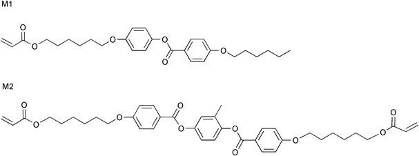 | ||
| Fig. 1 Liquid crystalline monomers with one (M1, top) and two (M2, bottom) reactive sites. | ||
The mechanical properties of an anisotropic network can be tailored by altering the ratio of M1 to M2 molecules in the monomer mixture.22 M2 acts as a crosslinker, connecting long chains of M1, as illustrated in Fig. 2. If the concentration of M2 is increased, the resulting network will be more densely crosslinked, and the modulus of the material will increase. For a uniaxial sample of poly(M1), dynamic thermal mechanical analysis shows that the modulus of a sample measured parallel to the long axis of the molecules is around 40 MPa (25 °C, 1 Hz), whereas for a similarly aligned sample of poly(M2) the modulus measured in the same direction is 1.1 GPa. A wide range of intermediate properties is therefore achievable by varying the ratio of M1 to M2 in the sample.
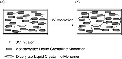 | ||
| Fig. 2 A mixture containing initiator, diacrylate and monoacrylate liquid crystalline monomers (a) can be polymerized by UV irradiation to form a crosslinked network (b). | ||
The thermomechanical properties of the material are also strongly influenced by the ratio of monoacrylate to diacrylate in the network. In liquid crystalline polymers anisotropic mechanical deformation is driven by the reduction in order that occurs during heating. Since the covalent bonds in the network preferentially appear along the molecular axis of the liquid crystalline units expansion is typically anisotropic, and the material expands most in a direction perpendicular to the director.15 This expansion is affected by the concentration of M2 in the sample, as it is known that polymers with higher crosslinking have lower thermal expansion coefficients, since intermolecular bonding is higher.23 Therefore higher concentrations of M2 are expected to reduce the overall expansion observed.
The contraction of uniaxially aligned samples in the direction parallel to the director is shown in Fig. 3 for liquid crystalline polymers with varying M2 content. All measurements were conducted on free-standing films approximately 60 µm thick, measured parallel to the director. Interestingly, the relationship between crosslinker content and maximum contraction achieved is not monotonic. While it might be expected that systems with the lowest crosslinker content would undergo the largest deformations, the data suggest otherwise. For the systems measured the maximum deformation is seen for the sample containing 12% crosslinker. For lesser concentrations, smaller deformations are achieved. We hypothesize that for these systems the motion of the liquid crystalline molecules is not sufficiently coupled to the polymer backbone for the microscopic reorientation of the molecules to translate to a macroscopic deformation of the sample (non-affine deformation). Based on these results we opt to use liquid crystalline polymers comprised of 88% M1 and 12% M2 in the subsequent studies described in this paper.
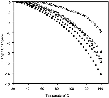 | ||
| Fig. 3 Contraction of monacrylate liquid crystal polymer films with varying M2 (crosslinker) content. Films contain 5% (○), 10% (□), 12% (■), 15% (▲) and 20% (△) crosslinker (by weight). The length change is normalized to the initial length at 25 °C after annealing of the sample. | ||
For the sample with 12% crosslinker, the thermomechanical behavior perpendicular to the axis of orientation was also measured. The change in length of the sample as a function of temperature in the directions parallel and perpendicular to this axis are shown in Fig. 4. As expected from its uniaxial nature, the absolute value of the expansion coefficient along the axis of molecular ordering is lower than the coefficient for the direction perpendicular to this axis. Dynamic thermal mechanical analysis of this material at 30 °C was used to determine the Young's modulus to be 22 MPa in the direction perpendicular to the molecular ordering and 125 MPa in the parallel direction (measured in tension at a frequency of 1 Hz). Note that these values fall sharply around room temperature since the glass transition temperature of the material is also centered around 22 °C to 25 °C.
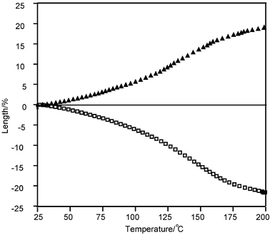 | ||
| Fig. 4 Elongation and contraction of uniaxially aligned poly(M1(88%) + M2(12%)) films as a function of temperature, measured parallel (□) and perpendicular (▲) to the axis of molecular ordering. The length change is normalized to the initial length at 25 °C after annealing of the sample. The parallel sample contracts by 21%, and the perpendicular sample expands by 19%. | ||
Optical characterization of liquid crystalline polymer films
The thermooptical properties of uniaxially aligned samples can provide insight into the thermomechanical behavior of these films. Uniaxially aligned liquid crystalline polymers exhibit anisotropic optical properties. Specifically, these films are birefringent, exhibiting different indices of refraction in a direction parallel (ne) and directions perpendicular (no) to the axis along which the molecules are aligned. This effect can be observed by placing a uniaxially aligned sample between crossed polarizers, with the director at 45° with respect to the fast axis of each polarizer. The liquid crystalline film acts as a waveplate, introducing a path length difference Λ between the ordinary and extraordinary components of the linearly polarized light incident upon it. This path length difference is dependent on the thickness of the film (d), and is related to the ordinary and extraordinary indices of refraction (no and ne) by the equation Λ = d(|ne − no|). The ratio between the intensity of the incident (Io) and transmitted (I) beams is a periodic function given in the following equation: .24 Minimum intensity occurs at wavelengths (λo) for which Λ = mλo (where m is an even integer). It is therefore possible to determine birefringence (Δn = no
−
ne) from transmission measurements through uniaxially aligned films oriented at 45° to crossed polarizers (so long as d is known).25
The thermomechanical measurements described in the previous section suggest that as a uniaxially aligned sample is heated, the order of the system is reduced. This requires the birefringence of the material to also decrease, since the long axes of the molecules will be on average ‘less aligned’ in one uniaxial direction. As the order is reduced the effective ne of the overall film will also decrease, while the effective no will increase. In order to show that the change in dimension of the 12% crosslinker sample does in fact result from the loss in order of the system, the birefringence of a free-standing uniaxially aligned sample was measured using a technique described in the literature25 and the results are shown in Fig. 5.
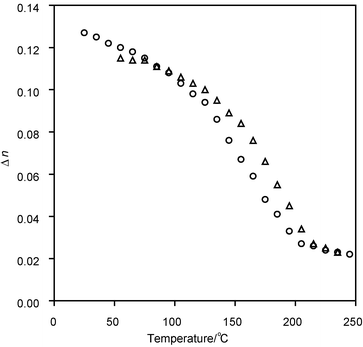 | ||
| Fig. 5 Birefringence as a function of temperature for uniaxial poly(M1(88%) + M2(12%)) sample measured during heating (○) and then cooling (△). The birefringence shown is for a wavelength of 589 nm. | ||
The birefringence at room temperature was determined to be 0.12, which corresponds to an order parameter of around 0.6, a value which is normal for these types of materials. During heating the birefringence, and thus the order parameter, of the sample declined steadily, and above 215 °C the birefringence that could be measured became very small. This corresponds to a close to isotropic phase of the material, when the orientation of the liquid crystalline units within the sample should be almost completely random. On cooling most of the birefringence was recovered, although there was some hysteresis in the curve, that most likely occurred due to free volume relaxation of the film.26 Nonetheless, the high birefringence reachieved on cooling suggests that most of the ordering was recovered, and that the change in dimensions observed during thermomechanical testing did indeed result from a loss of order in the material. The birefringence curve also explains the shape of the curves presented in Fig. 4 with the steepest changes between 100 and 200 °C and a leveling off when the sample approaches the isotropic phase.
Surface anchored reference samples
For integration into microactuator devices, the mechanical behavior of a liquid crystalline polymer mounted onto a substrate must be considered. We expect that anchoring a sample to the surface of a substrate will introduce stresses and other constraints that are not seen for macroscopic samples, since deformation will be suppressed by the substrate. In this section we examine the thermal behavior of a number of liquid crystalline polymer thin films prepared and characterized on substrates. Four different director profiles are considered. They are: uniaxial alignment in the plane of the substrate (planar alignment), homeotropic, isotropic and cholesteric. These configurations are illustrated schematically in Fig. 6.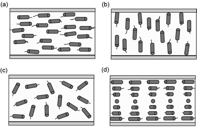 | ||
| Fig. 6 (a) Uniaxial planar alignment, in which the director points in one direction in the plane of the substrate; (b) homeotropic alignment, in which the molecules are aligned perpendicular to the substrate; (c) isotropic phase, in which the liquid crystalline molecules are randomly aligned; and (d) cholesteric phase in which the director lies in the plane of the substrate, but the direction of alignment within adjacent planes rotates around an axis perpendicular to the substrate. | ||
The cross-sectional thickness profile of each film as a function of temperature was measured using white light interferometry, and sample profiles are shown in Fig. 7 for the isotropic configuration. Each sample was heated to 200 °C (the maximum temperature measured) before measuring to eliminate deformations that occur as a result of free volume relaxation during the first heating step. At least two samples with each director configuration were measured at a number of different temperatures during heating and cooling, and the observed deformations were found to be reversible and repeatable with reasonable precision.
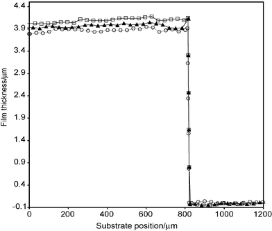 | ||
| Fig. 7 Step profile of isotropic film and substrate during temperature cycling. Measurements were taken during the cooling cycle at 200 °C (□), 100 °C (▲) and 25 °C (○), and were fully reversible. The profile is measured along a cut in the film, relative to the substrate. | ||
A summary of the total change in dimension observed for films with each director profile is shown in Table 1. These values are expressed as (Δd/do) × 100%, where do is the initial thickness and Δd is the total change in thickness when heated to 200 °C.
| Director profile | Measured expansion at 200 °C |
|---|---|
| Isotropic | 5% |
| Homeotropic | 2% |
| Planar | 9% |
| Cholesteric | 11% |
Interestingly, the homeotropic film actually expanded when heated, rather than contracting along the direction of alignment (perpendicular to the substrate). Recall from Fig. 4 that for free-standing samples measured parallel to the long axis the samples were able to undergo a significant (22%) reduction in length when heated to 200 °C. For surface anchored films, this does not occur. In order for the sample to contract in a direction perpendicular to the substrate (reducing the overall thickness) the anisotropic units must expand in the plane of the substrate. However, the interaction between the sample and the substrate prevents this expansion. In order to verify the effect of anchoring the sample to the substrate, finite element models were also developed. The parallel and perpendicular thermal expansion coefficients (α|| and α⊥) of the liquid crystalline polymer were first determined by creating models for the free-standing thin films that were measured using thermal mechanical analysis. In these models the external boundary conditions applied to the film mimicked the actual conditions during measurement (clamped in all three dimensions at one end, and clamped in two dimensions at the other end but free to move along the long axis of the film). The thermal expansion coefficients required to achieve the deformations measured when the samples were heated from 25 °C to 200 °C were determined. These coefficients were then included in the model for the homeotropic, surface-anchored film. In this case the thermal expansion coefficient perpendicular to the plane of the film (αy) was defined as α||, and the expansion coefficients in both other directions (αx and αz) were set equal to α⊥. In order to emulate the effect of the glass substrate external boundary conditions were imposed on the sample, constraining motion in all three dimensions along the bottom face of the film. When a thermal load of 175 °C (corresponding to heating from 25 °C to 200 °C) was applied the model predicted an overall thickness increase of 5%, which is very different from the behavior of free-standing films. The changes in thicknesses predicted for varying boundary conditions applied to a homeotropic film are shown in Fig. 8. Further details of the modelling can be found in the Experimental section of this paper.
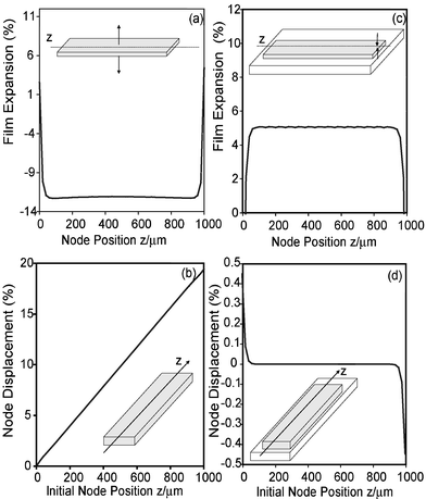 | ||
| Fig. 8 Finite element models for thin films with liquid crystalline moieties aligned homeotropic to the plane of the film. The free-standing film is modeled after the measurement configuration employed for thermal mechanical analysis, clamped in all three dimensions at one end, and clamped in the x and y directions in the other (a,b). When the film is heated to 200 °C the model predicts a contraction in the direction that the liquid crystalline units are aligned, to a maximum value of −13% at the center of the film (a). Parallel to the long axis of the film (perpendicular to the direction along which the molecules are aligned) the model predicts an increase in length of almost 20% (b) (which corresponds well to measured results). When the film is confined to a substrate, a very different behavior is observed upon heating (c,d). The thickness of the film actually expands by a few percent (c), since the substrate prevents the film from expanding in the z direction (d). For the case of substrate mounted films the model predicts that the length remains fairly constant, with a sort of ‘wrinkling’ appearing at either end of the film, due to the large stresses generated. | ||
Substrate-induced confinement was also observed for the films in which the liquid crystalline units were initially oriented parallel to the plane of the substrate (planar and cholesteric). These films were expected to expand upon heating, which was in fact observed. However, the cholesteric film underwent a larger increase in thickness than the planar film. This is because in order for the planar film to expand there must be an accompanying contraction along the direction of orientation which is concentrated in one direction and is constrained by the substrate. For the cholesteric film the contraction occurs equally in all directions in the plane, distributing the stress more uniformly in many directions than for the planar film. This allows a larger overall expansion (11%) to be achieved. This expansion matches very well with the modelled value obtained using finite element modelling. In this model the bottom face of the film was constrained in all three dimensions. For the cholesteric film the thermal expansion coefficients within the plane of the film (αx and αz) were calculated by averaging the parallel and perpendicular thermal expansion coefficients (α|| and α⊥) determined above (αx = αz = [α|| + α⊥]/2). The thermal expansion coefficient in the direction perpendicular to the plane of the film (αy) was assigned the value α⊥. The results of this modelling are shown in Fig. 9. While the overall expansion of these films is considerably less than free-standing uniaxially aligned films (a situation which is again predicted by finite element models), it is still a significant amount that is potentially useful in linear microactuators.
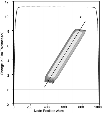 | ||
| Fig. 9 Finite element results for a cholesteric film fixed on the substrate. When heated from 25 °C to 200 °C the film expands by 11% at the center. The film expands to a lesser degree at the edges, due to the confinement of the substrate. The graph indicates the change in thickness for nodes located along the z direction shown on the inset contour plot. | ||
Photopatterning
Patternability is an important requirement for materials being considered for use in MEMS. Liquid crystalline polymers can be patterned using a single-step mask exposure during photopolymerization.27 This exposure preserves liquid crystalline ordering in the polymerized areas. The unexposed material can either be washed away using a solvent such as acetone (single-phase patterning), or the sample can then be heated into the isotropic phase and subjected to a flood exposure in order to preserve random ordering in the remaining region (multi-phase patterning). These two concepts are illustrated schematically in Fig. 10. In the first case (single-phase patterning) the final product consists of well-defined patterned structures on a bare substrate. In the second case (multi-phase patterning) the final product is expected to be a smooth, solid film, with areas that exhibit differing thermomechanical behavior.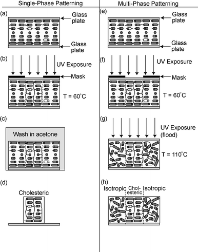 | ||
| Fig. 10 Process flow diagram for photopatterned liquid crystalline polymer films. Single-phase patterned films are fabricated by aligning a mixture of liquid crystalline monomers, chiral dopant, and UV initiator using surface alignment layers in a cell configuration (a), selectively polymerizing the mixture through a mask in the cholesteric phase (b), removing the top plate from the cell and washing away unpolymerized material in a solvent such as acetone (c), which yields a structured cholesteric film on a substrate (d). Multi-phase structures can be produced by aligning a mixture of liquid crystalline monomers, chiral dopant, and UV initiator using surface alignment layers in a cell configuration (e), polymerizing the mixture through a mask (f), and removing the mask, heating the sample into the isotropic phase, and flood exposing the sample to polymerize unreacted monomers (g). The final result of this process is a solid film comprised of isotropic and cholesteric regions (h). | ||
Photographs of multi-phase photopatterned films are shown in Fig. 11. In each photograph the sample is shown between crossed polarizers, which cause the isotropic regions to appear black. The first sample was exposed in the cholesteric phase using a chrome mask with 400 µm lines separated by 100 µm gaps, and then flood exposed at an elevated temperature in order to preserve the isotropic phase. The cholesteric regions are well defined, and exhibit the characteristic ‘oily streak’ defect structure.28 This defect is caused by mismatch of alignment between adjacent regions, but is not expected to influence the thermomechanical behavior of the material since the liquid crystalline units remain aligned in the plane in both regions, and will therefore expand out of the plane when heated.
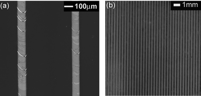 | ||
| Fig. 11 Photopatterned multi-phase structures: (a) 100 µm cholesteric lines separated by 400 µm of isotropic material, (b) 200 µm cholesteric lines separated by 200 µm of isotropic material. Both samples are viewed between crossed polarizers. | ||
The second sample was polymerized through a mask consisting of 200 µm lines with a pitch of 400 µm. The sample was then heated into the isotropic phase and flood exposed. Reasonably good uniformity was achieved over a 1 inch cell, a section of which is enlarged in Fig. 11(b).
Actuation of patterned structures
Reversible actuation of patterned cholesteric structures was observed using interferometry. The surface profile of a multi-phase sample as a function of temperature is shown in Fig. 12. In order to present the data clearly the profile is shown at three different temperatures measured during the cooling cycle, where the sample had been heated and cooled previously to eliminate the effects of free volume relaxation. The measurements shown are reversible, with the profiles at room temperature before and after thermal cycling matching closely. At room temperature the surface of the film is somewhat corrugated, an effect that has been seen previously and is believed to be caused by mass transport during polymerization.27 The thermomechanical behavior of the multi-phase film varies somewhat from that of the unpatterned reference samples. Based on the change in thickness of the cholesteric and isotropic reference films (11% and 5% respectively, when heated to 200 °C), we expected to see an overall change in thickness of 6% (360 nm) for this sample, which is itself 6 µm thick. However, the actual deformation was only around 100 nm (approximately 1.6%). This probably occurs because the cholesteric region of the patterned sample is less ordered than for the unpatterned reference sample measured previously due to the diffusion processes that took place during polymerization, or because some residual planar or cholesteric ordering has permeated the isotropic region of the film. Stress generated at the interface could also contribute to this lower than expected deformation.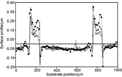 | ||
| Fig. 12 Surface profile of a multi-phase photopatterned substrate at 200 °C (■), 100 °C (▲), and 25 °C (○). As the sample is cooled from 200 °C to 25 °C the height of the photopatterned relief structures decreases by approximately 100 nm (1.6%). | ||
A much larger, reversible deformation was observed for single-phase patterned samples. The surface profile of a single-phase sample as a function of temperature is shown in Fig. 13. The initial thickness of the film was 16.6 µm, which increased by 8.4% (1.4 µm) when the sample was heated to 200 °C. This change in thickness was fully reversible, as the sample returned to its initial height upon cooling. A slight curvature is visible in the surface profile of the patterned areas at all temperatures. This curvature is quite small if the scales along the z and x axes are taken into account—the slope of the structure is less than 1°. This is most likely caused by diffusion that occurs during polymerization.27 Diffusion of the monomers may also be responsible for the fact that the overall change in height (as a percentage of total height) is slightly less for this sample than for the unpatterned chiral reference sample (8.4% vs. 11%), since this effect would reduce the overall order of the liquid crystalline moieties. This idea is supported by comparing the change in thickness of the unpatterned surface anchored isotropic and cholesteric reference samples as a function of temperature (as measured relative to the substrate at a cut in the sample) with the change in thickness of the single-phase patterned sample. These data are illustrated in Fig. 14, and it is found that at 100 °C the change in thickness of all three samples is quite similar, while at 200 °C the thickness of the unpatterned cholesteric reference sample has increased the most, the thickness of the unpatterned isotropic reference film has increased the least, while the single-phase patterned film falls midway between. We therefore conclude that the ordering of this sample is in between those of the unpatterned cholesteric and isotropic samples.
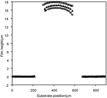 | ||
| Fig. 13 The cooling cycle of a thermally actuated photopatterned film consisting of patterned lines on a bare substrate, measured at 200 °C (□), 100 °C (▲), and 25 °C (○). The patterned structure expanded by 1.4 µm from an initial thickness of 16.6 µm at 25 °C (measured at the peak of the patterned area) when heated to 200 °C, and returned to its original height upon cooling. This corresponds to a total change in thickness of 8.4%. | ||
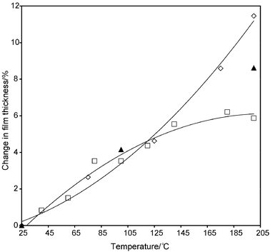 | ||
| Fig. 14 Percent change in film thickness as a function of temperature for an unpatterned surface-anchored isotropic reference sample (□), an unpatterned surface-anchored cholesteric reference sample (◇) and a single-phase patterned sample (▲) (measured relative to the thickness of the film at 25 °C). At 100 °C all three samples have expanded by a similar amount. At 200 °C the cholesteric reference sample (which was prepared as a solid film in a one inch cell) undergoes the largest expansion, the isotropic reference sample (also prepared in a cell) undergoes the smallest expansion, and the single-phase patterned film falls in between. The solid lines shown are intended to guide the eye. | ||
Conclusion
The properties of thermoresponsive, anchored, microscaled liquid crystalline polymer films were investigated, in order to consider the feasibility of employing these films in MEMS-type devices. In all of the films UV polymerization and surface alignment techniques compatible with microscaled fabrication processes were employed.The thermomechanical behavior of free-standing and surface-anchored liquid crystalline polymer films was investigated, and it was found that anchoring the films to the substrate constrained the deformation of the material, an effect which was also confirmed by finite element analysis. However, cholesteric films were still able to expand by 11% of their initial thickness when heated, which could make them suitable for use as linear actuators.
Patterning of aligned liquid crystalline polymers was also demonstrated. Single-phase structures consisting of lines of cholesteric liquid crystalline polymer 200 µm wide and 17 µm tall were produced using a simple photopatterning procedure. The thermomechanical behavior of these structures was investigated, and found to be comparable with that of cholesteric reference films. Multi-phase patterning (i.e., alternating domains of aligned and isotropic liquid crystals) has also been demonstrated, and while they also exhibit reversible thermomechanical behavior, the overall change in dimension is less significant than for single-phase patterned structures.
We have demonstrated that surface aligned liquid crystalline polymers can be fabricated, patterned, and actuated with microscaled dimensions. While our investigation has focused on thermoactuated materials, there are a wide range of responsive liquid crystalline materials that could be shaped on the microscale using similar processes. Different configurations of surface alignment layers could also be used to make films that undergo bending type deformations from materials with higher moduli. We conclude that photopatterning of liquid crystalline polymers is a promising technique for the production of microactuators.
Acknowledgements
A.E. and M.B. would like to acknowledge financial support from the Natural Sciences and Engineering Research Council of Canada (NSERC), the informatics Circle of Research Excellence (iCORE), the Alberta Ingenuity Fund and Micralyne Inc.References
- S. R. Quake and A. Scherer, Science, 2000, 290, 1536–1540 CrossRef CAS; X. F. Wang, J. Engel and C. Liu, J. Micromech. Microeng., 2003, 13, 628–633 CrossRef CAS.
- C. Liu and Y. Bar-Cohen, in Proceedings of SPIE’s 6th Annual International Symposium on Smart Structures and Materials, ed. Y. Bar-Cohen, SPIE – Int. Soc. Opt. Eng., U. S. A., 1999, vol. 3669 Search PubMed.
- M. E. Harmon, M. Tang and C. W. Frank, Polymer, 2003, 44, 4547–4556 CrossRef CAS.
- M. Koch, A. G. R. Evans and A. Brunnschweiler, J. Micromech. Microeng., 1998, 8, 119–122 CrossRef CAS.
- S. E. Lyshevski, IEEE Trans. Aerosp. Electron. Syst., 2002, 38, 543–552 CrossRef.
- M. Kohl, B. Krevet and E. Just, Sens. Actuators, A, 2002, 97–8, 646–652 CrossRef.
- A. DellaSanta, D. DeRossi and A. Mazzoldi, Smart Mater. Struct., 1997, 6, 23–34 CrossRef CAS; E. Smela, O. Inganas, Q. B. Pei and I. Lundstrom, Adv. Mater., 1993, 5, 630–632 CrossRef CAS; E. Smela, O. Inganas and I. Lundstrom, Science, 1995, 268, 1735–1738 CrossRef CAS.
- E. T. Carlen and C. H. Mastrangelo, J. Microelectromech. Syst., 2002, 11, 408–420 CrossRef CAS.
- F. J. Davis, J. Mater. Chem., 1993, 3, 551–562 RSC; M. Warner and E. M. Terentjev, Prog. Polym. Sci., 1996, 21, 853–891 CrossRef CAS; H. Finkelmann, A. Greve and M. Warner, Eur. Phys. J. E, 2001, 5, 281–293 CrossRef CAS.
- H. Wermter and H. Finkelmann, e-Polymers, 2001, 1–13 Search PubMed.
- P. G. deGennes, M. Hebert and R. Kant, Macromol. Symp., 1997, 113, 39–49 CAS.
- H. Finkelmann and H. Wermter, in Abstracts of the American Chemical Society, American Chemical Society, Washington DC, U. S. A., 2000, vol. 219, paper 189 Search PubMed.
- M. Camacho-Lopez, H. Finkelmann, P. Palffy-Muhoray and M. Shelley, Nat. Mater., 2004, 3, 307–310 CrossRef CAS; Y. L. Yu, M. Nakano and T. Ikeda, Nature, 2003, 425, 145–145 CrossRef CAS; H. Finkelmann, E. Nishikawa, G. G. Pereira and M. Warner, Phys. Rev. Lett., 2001, 8701, 015501 CrossRef.
- K. D. Harris, C. W. M. Bastiaansen, J. Lub and D. J. Broer, Nano Lett., 2005, 5, 1857–1860 CrossRef CAS.
- G. N. Mol, K. D. Harris, C. W. M. Bastiaansen and D. J. Broer, Adv. Funct. Mater., 2005, 15, 1155–1159 CrossRef CAS.
- J. Kupfer and H. Finkelmann, Makromol. Chem., Rapid Commun., 1991, 12, 717–726 CrossRef.
- A. Komp, J. Ruhe and H. Finkelmann, Macromol. Rapid Commun., 2005, 26, 813–818 CrossRef CAS.
- M. E. Sousa, D. J. Broer, C. W. M. Bastiaansen, L. B. Freund and G. P. Crawford, Adv. Mater., 2006 Search PubMed , in press.
- A. L. Elias, K. D. Harris, C. W. M. Bastiaansen, D. J. Broer and M. J. Brett, in Smart Sensors, Actuators, and MEMS II, SPIE, Microtechnologies for the New Millennium, ed. Carles Cené, SPIE – Int. Soc. Opt. Eng., U. S. A., 2005, vol. 5836, pp. 41––55 Search PubMed.
- A. Buguin, M. H. Li, P. Silberzan, B. Ladoux and P. Keller, J. Am. Chem. Soc., 2006, 128, 1088–1089 CrossRef CAS.
- D. J. Broer, in Radiation Curing in Polymer Science and Technology: Polymerisation Mechanisms, ed. J. P. Fouassier and J. F. Rabek, 1993, vol. 3, pp. 383–443 Search PubMed.
- R. A. M. Hikmet and D. J. Broer, Polymer, 1991, 32, 1627–1632 CAS.
- W. D. J. Callister, Materials Science and Engineering, An Introduction, 5th edn, John Wiley & Sons, New York, 2000 Search PubMed.
- J. L. West, G. Q. Zhang, A. Glushchenko and Y. Reznikov, Appl. Phys. Lett., 2005, 86, 031111 CrossRef.
- D. J. Broer, H. Finkelmann and K. Kondo, Makromol. Chem., 1988, 189, 185–194 CrossRef CAS; M. J. Escuti, D. R. Cairns and G. P. Crawford, J. Appl. Phys., 2004, 95, 2386–2390 CrossRef CAS; J. Gandhi and J. Anderson, SID Int. Symp. Dig. Tech. Pap., 2002, 33, 582–585 Search PubMed.
- D. J. Broer and G. N. Mol, Polym. Eng. Sci., 1991, 31, 625–631 CrossRef CAS.
- B. M. I. van der Zande, J. Steenbakkers, J. Lub, C. M. Leewis and D. J. Broer, J. Appl. Phys., 2005, 97, 123519 CrossRef.
- F. Zhang and D. K. Yang, Phys. Rev. E, 2002, 66, 041701 CrossRef CAS.
| This journal is © The Royal Society of Chemistry 2006 |
