Morphology of polymer/fullerene bulk heterojunction solar cells
Harald
Hoppe†
* and
Niyazi Serdar
Sariciftci
Linz Institute for Organic Solar Cells (LIOS), Physical Chemistry, Johannes Kepler University Linz, Altenbergerstr. 69, A-4040 Linz, Austria. E-mail: harald.hoppe@tu-ilmenau.de
First published on 28th November 2005
Abstract
Within the different organic photovoltaic devices the conjugated polymer/fullerene bulk heterojunction approach is one of the foci of today's research interest. These devices are highly dependent on the solid state nanoscale morphology of the two components (donor/acceptor) in the photoactive layer. The need for finely phase separated polymer–fullerene blends is expressed by the limited exciton diffusion length present in organic semiconductors. Typical distances that these photo-excitations can travel within a pristine material are around 10–20 nm. In an efficient bulk heterojunction the scale of phase separation is therefore closely related to the respective exciton diffusion lengths of the two materials involved. Once the excitons reach the donor/acceptor interface, the photoinduced charge transfer results in the charge separation. After the charges have been separated they require percolated pathways to the respective charge extracting electrodes in order to supply an external direct current. Thus also an effective charge transport relies on the development of a suitable nanomorphology i.e. bicontinuous interpenetrating phase structures within these blend films. The present feature article combines and summarizes the experimental findings on this nanomorphology–efficiency relationship.
 Harald Hoppe | Harald Hoppe reveived his diploma degree in Physics at the University of Konstanz, Germany in 2000. He prepared his diploma studies in polymer physics under the mentorship of Professor Jacob Klein at the Department of Materials & Interfaces, Weizmann Insitute of Science, Israel. Thereafter he received his doctorate degree at the Linz Institute for Organic Solar Cells (LIOS) under the mentorship of Professor Niyazi Serdar Sariciftci at the Johannes Kepler University of Linz, Austria, in 2004. In spring 2005 he joined the group of Professor Gerhard Gobsch at the Technical University of Ilmenau as a post-doctoral research assistant. His main research activities are in the field of organic optoelectronics with a special focus on plastic solar cells. |
 Niyazi Serdar Sariciftci | Niyazi Serdar Sariciftci received his masters degree in Experimental Physics and a doctorate degree in Semiconductor Physics under the mentorship of Professor H. Kuzmany at the University of Vienna in 1986 and 1989, respectively. After a post doctoral period at Stuttgart University, Germany, with Professor M. Mehring, he joined the Institute of Polymer and Organic Solids at the University of California, Santa Barbara, with Professor Alan Heeger. He was appointed Chair and Professor in Physical Chemistry at the Johannes Kepler University of Linz in 1996. He is the Founding Director of the Christian Doppler Laboratory for Plastic Solar Cells and the Linz Institute for Organic Solar Cells (LIOS). His main research activities are in organic semiconductor physics and chemistry. |
1. Introduction: history, materials and tools
The field of conjugated polymer/fullerene solar cells was born with the discovery of the photoinduced electron transfer between the soluble poly(para-phenylenevinylene) (PPV) derivative MEH-PPV and the C60 Buckminsterfullerene.1 First bilayer devices delivered the proof of principle for solar energy conversion.2 With the introduction of the bulk heterojunction concept,3–6 the quantum efficiency of conjugated polymer/fullerene solar cells could be raised considerably.5The first morphology study dedicated to the MEH-PPV ∶ C60 bulk heterojunction system applying transmission electron microscopy was reported by Yang and Heeger.7 They selectively dissolved the fullerene from thin blend films using decahydronaphthalene, and observed both isolated and connected regions with characteristic size of about 10 nm, corresponding to the C60 phase. For increasing C60 content the authors reported increasing percolation and bicontinuous network formation of the C60 phase within the MEH-PPV network. Furthermore, the application of electron diffraction on MEH-PPV ∶ C60 blends with a weight ratio of approximately 1 ∶ 4 revealed a crystalline organization of the C60. The authors concluded the C60 to be present in the blend in the form of nanocrystallites having sizes of roughly 10 nm.7 C60 is truly a spherical molecule and this property of spatial symmetry allows for relatively high order in the fullerene phase—even within composites. This issue will be further elucidated in the following sections.
The next major step in the development of polymer–fullerene bulk heterojunction photovoltaics was achieved at the turn of the millennium by Shaheen et al.,8 demonstrating for the first time power conversion efficiencies of 2.5% at AM 1.5 standard solar irradiation. This report also laid the basis for many other investigations in the direction of studying the link between morphology and efficiency in these polymer–fullerene bulk heterojunctions.
Among organic solar cells, the polymer–fullerene blends5,6,9 have demonstrated competitive power conversion efficiencies. Interestingly, from the conjugated polymers only a few material classes have been employed in polymer–fullerene bulk heterojunctions: soluble poly(para-phenylenevinylene) (PPV) derivatives,5,8–20 polythiophenes (e.g. P3ATs),21–32 polyfluorenes,33,34 and poly(phenylene-ethynylene)-(para-phenylenevinylenes) (PPE-PPVs).35,36 These conjugated polymers have already enjoyed development for many years, especially for application in polymer light emitting diodes (PLEDs). It is even more intriguingly that among suitable fullerenes only one representative warrants the best power conversion efficiency for a decade, the soluble C60 derivative 1-(3-methoxycarbonyl)propyl-1-phenyl [6,6]C61 (PCBM).37Fig. 1 displays some representatives of the above-mentioned groups of conjugated polymers used in bulk heterojunction solar cell devices together with the most commonly used fullerene PCBM. Table 1 summarizes some of the best power conversion efficiencies reported among other device parameters for the same material systems.
 | ||
| Fig. 1 Several representatives of suitable conjugated polymers are shown together with the soluble C60 fullerene derivative PCBM. | ||
| Materials | Reference | Short circuit current | Open circuit voltage | Fill factor | Power conversion efficiency |
|---|---|---|---|---|---|
| a Corrected for spectral mismatch (factor 0.753) of the solar simulator. | |||||
| MDMO-PPV ∶ PCBM 1 ∶ 4 | 8 | 5.25 mA cm−2 @ 80 mW | 820 mV | 61% | 2.5%a |
| MDMO-PPV ∶ PCBM 1 ∶ 4 | 19 | 5.0 mA cm−2 @ 80 mW | 800 mV | 71% | 2.65%a |
| MDMO-PPV ∶ C70-PCBM 1 ∶ 4 | 17 | 7.6 mA cm−2 @ 100 mW | 770 mV | 51% | 3.0% |
| P3HT ∶ PCBM 1 ∶ 2 | 25 | 8.5 mA cm−2 @ 80 mW | 550 mV | 60% | 3.5% |
| P3HT ∶ PCBM 1 ∶ 2 | 26 | 15.9 mA cm−2 @ 110 mW | 560 mV | 47% | 3.8% |
| P3HT ∶ PCBM 1 ∶ 1 | 30 | 10.9 mA cm−2 @ 100 mW | 630 mV | 49% | 3.4% |
| P3HT ∶ PCBM 1 ∶ 0.8 | 31 | 11.1 mA cm−2 @ 80 mW | 640 mV | 55% | 4.9% |
| P3HT ∶ PCBM 1 ∶ 0.8 | 32 | 9.5 mA cm−2 @ 80 mW | 630 mV | 68% | 5.1% |
| PFDTBT ∶ PCBM 1 ∶ 4 | 33 | 4.7 mA cm−2 @ 100 mW | 1040 mV | 46% | 2.2% |
| PPE-PPV ∶ PCBM 1 ∶ 2 | 35 | 4.3 mA cm−2 @ 100 mW | 810 mV | 59% | 2.0% |
Traditionally electron microscopy served as an exploration tool for the bulk heterojunction morphology in thin films—mainly in the form of transmission electron microscopy (TEM) in connection with selected area electron diffraction (SAED).7 Later scanning electron microscopy (SEM) proved its effectiveness in resolving the fine structure of polymer–fullerene composites.38 Furthermore, atomic force microscopy (AFM) especially in the non-contact (or tapping) mode was applied to investigate the polymer–fullerene blend film topography,8,12,38,39 of which recently more sophisticated derivatives like Kelvin probe force microscopy have been used.40–42 Scanning near field optical microscopy (SNOM) detecting photoluminescence43 or photocurrent44,45 has been applied as well. Taking the results originating from these different techniques together yields today a rather conclusive picture of the underlying nanomorphology and its effect on power conversion efficiency in solar cell devices.
Meanwhile also theoretical work on optimized morphologies has been performed46 and the general understanding of today is converging towards some closely intermixed donor–acceptor blend, where the individual phases have a certain extend to allow for efficient transport of charges via percolated pathways towards the respective electrodes. The challenge, however, that remains to be resolved for each and every materials combination is the controlled self-organization during and after the film formation process towards the desired optimal morphology.
2. Morphology determining parameters
The morphology of the photoactive polymer-fullerene blend can be affected by controlling several production parameters during the film formation or by treatments afterwards. Experimentally the following parameters have been identified as most significant for their influence on the nanoscale morphology in these polymer–fullerene blends:a) the spin casting solvent,
b) the composition between polymer and fullerene,
c) the solution concentration,
d) the controlled phase separation and crystallization induced by thermal annealing, and finally
e) the chemical structure of the materials.
The chemical structures of polymer and fullerene determine to a large extent the solubility in common organic solvents and the miscibility between these two compounds. The solvent itself furthermore influences the drying time during film formation, whereas thermal annealing enables the crystallization and diffusion of one or both compounds in the blend leading to a coarsening of the phase separation.
2.1 Solvent
Already in the first study on conjugated polymer/fullerene D/A bulk heterojunction solar cells done by the Heeger group it was reported that the limited solubility of pure C60 in organic solvents and its tendency to crystallize during film formation prevents the use of high concentration blends.5 This limitation was overcome by the application of soluble C60 derivatives, developed previously.5,37 The soluble PPV derivative used was poly(2-methoxy-5(2′-ethyl-hexyloxy)-1,4-phenylenevinylene) (MEH-PPV).47 On changing the solvent from xylene to 1,2-dichlorobenzene “high-quality” spin cast MEH-PPV ∶ PCBM films with weight ratio compositions of up to 1 ∶ 4 were achieved.5 These devices outperformed pristine MEH-PPV devices with a photocurrent increased by two orders of magnitude at 430 nm 20 mW cm−2 monochromatic laser illumination.Shaheen et al. observed a dramatic power conversion efficiency increase upon changing the solvent from which the MDMO-PPV ∶ PCBM (1 ∶ 4 by weight) blend solution was spun.8 The authors reported a strong dependence of the performance on the solvent used: whereas toluene cast devices yielded power conversion efficiencies of only 0.9% the use of chlorobenzene almost tripled the efficiency. This increase was mainly due to an increase of the short circuit current (Fig. 2) and the authors attributed this to finer grain sizes in the thin film nanomorphology, revealed by atomic force microscopy (AFM).8
 | ||
| Fig. 2 Effect on photocurrent of the solvent used for spin casting the active layer, a blend of MDMO-PPV/PCBM 1 ∶ 4 by weight. Reprinted with permission from reference 8, Copyright 2001, American Institute of Physics. | ||
The difference in photocurrents could not be related to an increased photon absorption within the photoactive layers, since the transmittances of toluene and chlorobenzene cast films were nearly identical (see Fig. 3). Therefore the improved photocurrent was assigned to a change in the underlying blend nanomorphology.
 | ||
| Fig. 3 Optical transmission spectra of 100 nm thick MDMO-PPV ∶ PCBM (1 ∶ 4 by wt.) films spin coated onto glass substrates from either toluene (dashed line) or chlorobenzene (solid line) solutions (a). Incident photon to collected electron (IPCE) spectra for photovoltaic devices using these films as the active layer (b). Reprinted with permission from reference 8, Copyright 2001, American Institute of Physics. | ||
In another study on the MEH-PPV ∶ C60 system, Liu et al. correlated the solar cell device parameters with different solvents (xylene, chlorobenzene, 1,2-dichlorobenzene, chloroform and tetrahydrofuran). They claimed that non-aromatic solvents prevent intimate contact between the MEH-PPV backbone and C60, thus reducing the charge transfer efficiency and subsequently the photocurrent, but increasing the photovoltage. Also by AFM measurements they found tetrahydrofuran (THF) based devices to exhibit a larger scale of phase separation. Furthermore the authors used the phase image of the non-contact AFM scans to determine the ratio of C60 and MEH-PPV exposed to the surface of the film and correlated this to the observed open circuit voltages by a simple linear combination of the corresponding magnitude for the pristine devices.
More recently Rispens et al. have compared the surface topography of MDMO-PPV ∶ PCBM devices by varying the solvent from xylene (XY) through chlorobenzene (CB) to 1,2-dichlorobenzene (DCB). The authors found a decrease in phase separation from XY through CB to DCB.48 Furthermore they proposed a certain crystal packing of the PCBM molecules, with solvent molecules being introduced into the crystal lattice. These data were based on crystals grown from solution.48
Martens et al. have comparatively investigated the nanostructure of MDMO-PPV ∶ PCBM bulk heterojunctions by applying transmission electron microscopy (TEM) on films and cross-sections of films spin cast from toluene and chlorobenzene.39,40,49 On increasing the PCBM concentration in the blends, the authors observed increasing dark clusters and attributed these to the fullerene-rich phase.
 | ||
| Fig. 4 TEM cross-sectional view of 1 ∶ 4 MDMO-PPV ∶ PCBM films spin cast from toluene (a) and chlorobenzene (b) on a PET substrate. The darker regions were attributed to PCBM rich regions. Reprinted from reference 39, Copyright 2003, with permission from Elsevier. | ||
Since for the ratio 1 ∶ 1 (1 ∶ 2) of MDMO-PPV ∶ PCBM for toluene (chlorobenzene) cast films there was no phase separation visible, the authors concluded that a homogeneous blend of PCBM and MDMO-PPV exists around the PCBM clusters for the blends with a higher PCBM content. Interestingly the chlorobenzene based blends were able to incorporate more PCBM than the toluene based counterparts, thus the compatibility between MDMO-PPV and PCBM seems to be influenced by the choice of solvent. Systematically the PCBM clusters in the toluene cast films were larger in size (up to several 100 nm) as compared to chlorobenzene cast films (less than 100 nm). In the TEM cross-sections of films spin cast on PET the fullerene-rich clusters are visible as darker regions (see Fig. 4).
Furthermore Martens has shown by AFM that the drying time is an important parameter for the size of the phase-separated structures. By introducing a hot air flow over a drying film, the drying time could be decreased and consequently the extent of phase separation was reduced.40 Here the film thickness was kept constant by a first fast thickness determining step, which was applied prior to the drying. Then the films obtained with the same chlorobenzene based solution were dried for different times.
Our recently published study on the nanoscale morphology of MDMO-PPV ∶ PCBM solar cells was also triggered by the findings of Shaheen et al.8 and aimed towards the decoding of the different phases within these MDMO-PPV ∶ PCBM blends cast from both toluene and chlorobenzene.38 Furthermore the different power conversion efficiencies caused by these morphologies needed a deeper understanding. In agreement with prior studies, a large difference in the scale of phase separation could be identified as major difference between toluene and chlorobenzene cast blends (see Fig. 5).
 | ||
| Fig. 5 Tapping mode AFM topography scans of MDMO-PPV ∶ PCBM 1 ∶ 4 (by weight) blended films, spin cast from (a) chlorobenzene and (b) toluene solution. The toluene cast film exhibits height variations that are one order of magnitude larger than those on chlorobenzene cast films. Features of a few hundred nanometers in width are visible in (b), while features in (a) are around 50 nm. (Reproduced from reference 38 with permission, Copyright 2004, Wiley VCH.) | ||
For the first time we used high-resolution scanning electron microscopy (HR-SEM) to image cross-sections of toluene and chlorobenzene cast MDMO-PPV ∶ PCBM blends (see Fig. 6). Thereby much smaller “nanospheres” became observable and have been assigned to the polymer MDMO-PPV in a coiled conformation. It has been suggested previously that conjugated polymers are present as little particles and thus form with the solvent rather dispersions than solutions.50
 | ||
| Fig. 6 SEM cross-sections of chlorobenzene (a, b) and toluene (c, d) based MDMO-PPV ∶ PCBM blends. Whereas chlorobenzene based blends are rather homogeneous, toluene cast blends reveal large PCBM clusters embedded in a polymer-rich matrix or skin-layer. Small features—referred to as “nanospheres”—are visible in all cases and can be attributed to the polymer in a coiled conformation. The blending ratio is depicted in the lower right corner. (Reproduced from reference 38 with permission, Copyright 2004, Wiley VCH.) | ||
The commonly observed larger scale of phase separation of the toluene cast MDMO-PPV ∶ PCBM blends has been interpreted as the main reason for the reduced photocurrents as compared to the chlorobenzene cast blends. Especially a lower charge carrier generation efficiency could be understood as a result of too small exciton diffusion lengths (10–20 nm) for reaching the interface between the large fullerene clusters (200–500 nm) and the polymer. Experimentally it has been identified that indeed some unquenched photoexcitations give rise to residual PCBM photoluminescence in toluene cast blends, whereas in chlorobenzene cast blends the fullerene photoluminescence could not be detected any more (see Fig. 7).38
 | ||
| Fig. 7 PL spectra for pure MDMO-PPV, pristine PCBM and blends of the two are shown. It is clearly visible that the PCBM peak at ∼735 nm is found for the toluene (Tol) cast blend, whereas for the chlorobenzene (CB) cast blend no such peak occurs. (Reproduced from reference 38 with permission, Copyright 2004, Wiley VCH.) | ||
However, the specific photoluminescence signal of even bare PCBM films was very small (<1%) when compared to the luminescence of the pristine polymer MDMO-PPV and therefore it is not sufficient to explain the 2–3 fold difference in the photocurrents observed earlier.8 The smaller photoluminescence efficiency of PCBM is due to the symmetrically forbidden LUMO–HOMO transition in fullerenes as well as due to strong intersystem coupling to the dark triplet state. In time-dependent photoluminescence measurements for chlorobenzene based blends it has been shown that the life time of the PCBM singlet state was indeed decreased by addition of the polymer.51 Furthermore it should be noted that around the singlet exciton life time almost all of the excitons are already in the triplet state due to the rapid intersystem crossing (see reference 52). Since the total number of optically observable photoexcitations in the fullerene phase is so small, but the contribution of the fullerene to the spectral photocurrent is vital, it has to be concluded that indeed triplet excitons take part to a large extent in the photocurrent generation. This statement is supported by the large triplet exciton diffusion lengths reported for C60-based bilayer devices, where the photocurrent generation is indeed dominated by those triplets.52 This however leads to the conclusion that this small photoluminescence signal of the singlet excitons observed in toluene cast MDMO-PPV ∶ PCBM blends can not sufficiently explain the observed overall photocurrent loss.
Furthermore, if the large fullerene clusters or domains were the reason for the decrease in photocurrent, the charge generation due to the absorption of the polymer should not be affected at all. This however is in contrast to the experimental observation that indeed the spectral photocurrent is smaller over the whole wavelength range detected.8,38 In Fig. 8 experimentally determined spectral photocurrents (incident photon to collected electron, IPCE) for different MDMO-PPV ∶ PCBM mixing ratios and for the two solvents, chlorobenzene and toluene, are depicted for comparison. The peak around 350 nm as well as the little kink slightly above 700 nm can be clearly assigned to the absorption of PCBM, whereas the broad absorption feature between 400–550 nm stems from the MDMO-PPV (compare to absorption spectra in reference 53). Therefore it is evident that PCBM contributes to a large extent to the photocurrent. It has been calculated for the 1 ∶ 4 blend that the PCBM contributes more than 50 percent to the absorption at standard AM 1.5 solar spectrum irradiation.53
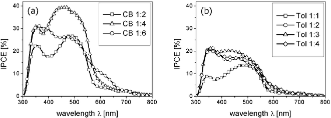 | ||
| Fig. 8 IPCE spectra for chlorobenzene (a) and toluene cast blends (b) are shown. The photocurrents of the toluene cast blends are lower over the whole spectral range, but not due to missing PCBM absorption, as the PCBM absorption peak is clearly present at about 350 nm. Reproduced from ref. 38 with permission, Copyright 2004, Wiley VCH) | ||
This leads to the conclusion that another loss mechanism is required to explain the lower overall photocurrents of toluene cast polymer–fullerene bulk heterojunctions. McNeill et al. resolved the local photocurrent obtained on MDMO-PPV ∶ PCBM toluene cast blends and revealed that the photocurrent is considerably reduced on top of the elevations caused by the PCBM clusters (see Fig. 9), whereas it stayed nearly constant on chlorobenzene cast blends.45 The authors proposed several mechanisms to explain this, among them lower visible light absorption inside the fullerene clusters but also an electron insulating polymer shell around the fullerene clusters.
 | ||
| Fig. 9 Height and local photocurrent signal obtained by near-field scanning photocurrent measurements. At the top both the topographic (left) and the photocurrent (right) images are shown. Reprinted from reference 45, Copyright 2004, with permission from Elsevier. | ||
Indeed, we were able to resolve the proposed polymer-“skin” structure which envelopes the fullerene nanoclusters in toluene cast films using high-resolution SEM measurements (see Fig. 10, right hand side).38,41 The cross sectional view clearly shows that the fullerene cluster is embedded into a 10–30 nm thick “skin”, presumably consisting of the polymer-rich phase. Using Kelvin probe force microscopy we could confirm this by the detection of a considerably increased work function on top of the embedded clusters.41 The larger work function on top of the clusters as compared to the polymer-rich matrix around the clusters and on chlorobenzene based blends is a clear signature for an increased hole density at the film surface, which in turn points to the presence of the hole conducting polymer.41
 | ||
| Fig. 10 Topography (a) and work function (b) of a toluene cast MDMO-PPV ∶ PCBM blend film measured by Kelvin probe force microscopy (KPFM). A clear correlation between the topographic hills caused by the PCBM clusters in (a) and the locally highest work functions in (b) is observed. The high work function regions can be understood as locally hole enriched areas, thus referring to the polymer-skin on top of most of the PCBM clusters (reproduced with permission from reference 41). | ||
The presence of the polymer skin layer around the fullerene clusters represents now a severe loss mechanism of the photocurrent for two reasons: a) electrons, which are accelerated to the top-aluminium electrode, have to penetrate this hole-rich layer and suffer recombination and b) holes in the polymer skin, which survive the recombination by the electrons in the polymer-skin, would have to travel too far around the fullerene clusters to reach the hole collecting PEDOT ∶ PSS electrode. However, due to the work function difference of the electrodes a strong electric field is present inside the photoactive layer. Therefore the charge carriers are accelerated along the electric field and most of the photogenerated holes will simply recombine at the interface to the fullerene clusters underneath the polymer skin layer. This issue is illustrated in Fig. 11 for clarity.
 | ||
| Fig. 11 The schematic clarifies the differences in chlorobenzene (a) and toluene (b) based MDMO-PPV ∶ PCBM blend film morphologies when employed as photoactive layer. In (a) both the polymer nanospheres as well as the fullerene phase offer percolated pathways for the transport of holes and electrons, respectively. In (b) electrons and holes suffer recombination, as the percolation is not sufficient. A strong electric field across the blend film, originating from the difference in the electrode work function, forces the charge carriers to travel orthogonal to the electrodes. Reprinted from reference 54, Copyright 2005, with permission from Elsevier. | ||
The exploration of the morphological differences between chlorobenzene and toluene cast MDMO-PPV ∶ PCBM blend films made it clear that not only the observed larger scale of phase separation but rather the difference in the material's phase percolation and thus charge transport properties influences the observed photovoltaic performance. Therefore it becomes obvious that e.g. the charge carrier mobility measured in these devices has to be a function of the morphology simply for geometrical reasons.
2.2 Influence of blending ratio
In the very first report on MEH-PPV ∶ PCBM bulk heterojunction solar cells the authors found the best performance for a blending ratio of 1 ∶ 4 between the two constituents (polymer ∶ fullerene).5 Many works thereafter confirmed this result, also for blends with the very similar MDMO-PPV. Since the photoluminescence of MEH-PPV could be quenched efficiently with much smaller amounts of fullerenes (less than 5%),55 the conclusion would be that efficient charge transport is still prohibited for smaller volume ratios of the fullerene due to insufficient fullerene phase percolation. Indeed, in the first morphological study on the MEH-PPV ∶ C60 system spun from dichlorobenzene Yang and Heeger did see more interconnections between the C60 domains with increasing fullerene concentration.7 Using transmission electron microscopy the (220) Debye ring of C60 crystals could be detected and the authors claimed a crystallite size of 10 nm or even less for the C60 phase.Gao et al. discussed the solar cell device parameters “short circuit photocurrent” (Isc) and “open circuit voltage” (Voc) of MEH-PPV ∶ C60 bulk heterojunctions in terms of their dependence on the blending ratio.10 Whereas the Voc dropped upon the addition of only small amounts of C60 to MEH-PPV, the photocurrent and also the power conversion efficiency were still increasing up to the largest C60 content of 80%. The increased photocurrent can be therefore related to an improved charge transport or collection efficiency. In agreement with these results also Liu et al. observed a decreasing Voc but increasing fill factor for higher C60 concentrations in blends with MEH-PPV.12
Using TEM39,56 and SEM38 it was shown that for increasing PCBM concentrations in MDMO-PPV ∶ PCBM blends the fullerene cluster size is growing accordingly.
Recently van Duren et al. reported a comprehensive study relating the morphology of MDMO-PPV ∶ PCBM blends cast from chlorobenzene to solar cell performance.51 The authors applied a variety of techniques including AFM, TEM, photoluminescence (PL), depth profiling with Time-of-Flight Secondary Ion Mass Spectrometry (TOF-SIMS) and standard solar cell characterization. The compositions between MDMO-PPV and PCBM were spanned over a wide range. After a rather homogeneous mixing for PCBM contents less than 50%, the authors claim a rather abrupt improvement in the device properties with the observed onset of phase separation around 67% PCBM content. By labeling of PCBM with deuterium, the composition of the fullerene could be followed by TOF-SIMS throughout the depth of the active layer with the result of a rather even distribution.
Time-dependent PL measurements revealed that only a small addition of PCBM to MDMO-PPV yields an effective reduction of the singlet exciton lifetime.55 On the other hand, the addition of a small fraction of MDMO-PPV to PCBM resulted only in a gradual reduction of the PCBM fluorescence lifetime, indicating the relatively large PCBM domains to be “rather pure”.51 The normalized fluorescence decay curves are plotted in Fig. 12.
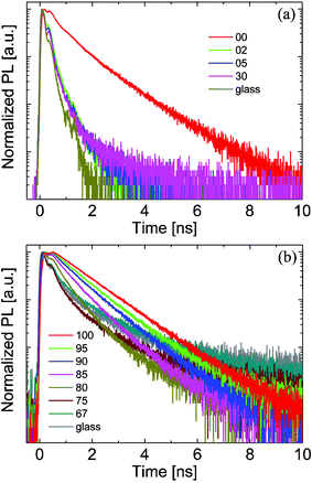 | ||
| Fig. 12 Normalized fluorescence lifetime traces for MDMO-PPV ∶ PCBM blends with varying composition. Here the numbers refer to the weight percentage of the PCBM in the blends. In (a) the MDMO-PPV decay is probed at 584 nm, whereas (b) shows the PCBM decays detected at 722 nm. The excitation wavelength is in both cases 400 nm. (Reproduced from reference 51 with permission, Copyright 2004, Wiley VCH.) | ||
Furthermore the authors confirmed earlier results8 that the maximum efficiency of MDMO-PPV ∶ PCBM blends was reached at a PCBM concentration of 80% (i.e. a ratio of 1 ∶ 4), which seemed to be mainly influenced by the improved fill factor at those high concentrations, whereas the short circuit current reached a maximum at about 75% (see Fig. 13).
 | ||
| Fig. 13 I–V curves (a), short circuit photocurrent and power conversion efficiency (b), and fill factor together with the open circuit voltage (c) for MDMO-PPV ∶ PCBM blends with varying PCBM content. (Reproduced from reference 51 with permission, Copyright 2004, Wiley VCH.) | ||
In the nanomorphology study we have measured similar trends of photocurrent, Voc and fill factor for both chlorobenzene and toluene based MDMO-PPV ∶ PCBM blends.38 Interestingly we observed the fill factor breaking down for a highly PCBM loaded polymer–fullerene blend at a ratio of 1 ∶ 6 (ca. 86% PCBM). As the polymer concentration is reduced to about 14%, one can expect the percolation—and thus accordingly the charge transport—of these spherical polymer particles to be limited. Indeed it is even visible in some cross-section SEM images that the polymer nanosphere density was too little to percolate completely throughout the blend layer (see Fig. 14). Interestingly a kind of layering of the MDMO-PPV on top of the PEDOT ∶ PSS layer could be found as well.
 | ||
| Fig. 14 SEM cross-section image of MDMO-PPV ∶ PCBM 1 ∶ 6 bulk heterojunction spin cast from chlorobenzene. It is clearly visible that the polymer nanospheres are more diluted in the blend than in blends with lower PCBM contents. (Reproduced from reference 38 with permission, Copyright 2004, Wiley VCH.) | ||
Generally, if the system is changed, the optimum mixing ratio has to be determined again. For example in regio-regular-P3HT ∶ PCBM bulk heterojunctions considerably smaller fullerene contents yield optimum solar cell efficiencies.25,27,30–32 This demonstrates once again that changing one component in the polymer–fullerene–solvent system will affect the morphology critically.
2.3 Influence of solution concentration
To investigate the influence of the solution concentration, solutions of different concentrations but with constant mixing ratios between MDMO-PPV and PCBM (1 ∶ 4) were prepared and spin cast from toluene solutions. AFM scans reveal that the fullerene cluster size (Fig. 15) and the average film thickness are increased with higher concentration.38 | ||
| Fig. 15 AFM scans of spin cast films with the same mixing ratio between MDMO-PPV and PCBM (1 ∶ 4 by weight), but with different total concentrations in the precursor toluene solution. Increasing the total concentration from 0.50 wt.% up to 1.50 wt.% (corresponding MDMO-PPV conc. of 0.10 wt.-% to 0.30 wt.%) results in a strong increase of the PCBM cluster sizes. Scan size is 5 µm × 5 µm, z-ranges are 100 nm, 150 nm and 200 nm (left to right). (Reproduced from reference 38 with permission, Copyright 2004, Wiley VCH.) | ||
Therefore the extent of phase separation does not only scale with an increasing fullerene fraction but also with an increasing total concentration of the precursor solution.38 To investigate whether the clusters are present already in solution or built up during film formation, we have carried out a study with a more extended concentration regime, keeping the MDMO-PPV ∶ PCBM blend ratio constant at 1 ∶ 4. The results from AFM tapping mode measurements and optical microscopy are summarized in Fig. 16.
 | ||
| Fig. 16 Study as in Fig. 15 with constant MDMO-PPV ∶ PCBM blend ratio of 1 ∶ 4, but with an extended range of concentrations in precursor toluene solutions, (a–c) AFM and (d–f) optical images. Whereas 0.20 wt.% and 0.33 wt.% MDMO-PPV concentration compare well to earlier results, 0.50 wt.% results in a reduced dimension of phase separation. Scan sizes are in all cases 5 µm × 5 µm, z-ranges are 100 nm, 150 nm and 100 nm (from (a) to (c)). The corresponding optical images (d–f) give information about the amount of precipitated PCBM. (Concentration shown in the image corresponds to that of MDMO-PPV, the total solute concentration is five times larger.) | ||
Interestingly the trend of increasing cluster sizes, observed in the concentration regime between 0.1 wt.% and 0.3 wt.%, is reversed for concentrations as high as 0.5 wt.% of MDMO-PPV, for which the solution becomes notably viscous and PCBM precipitates heavily. Note that the total concentrations (including PCBM) are five times the MDMO-PPV concentration shown in the images. From the optical images in Fig. 16 the amount of precipitated PCBM can be estimated. At higher concentrations there is a larger amount of precipitated PCBM observed, according to the independently determined solubility of 1 wt.% PCBM in toluene (see below). It should be noted that for all studies performed no filtering of solutions was applied, to guarantee the authenticity of the solution concentration quoted. For example in the case of 2.5 wt.% total concentration it can be expected that the mixing ratio in the solution would be altered considerably due to filtering. However, since the precipitated fullerene is visible in the optical images, it is clear that the mixing ratio in the film shown by AFM is different from that prepared in solution.
From independent optical measurements on PCBM solutions, the solubility of PCBM was determined to be roughly 1 wt.% in toluene and 4.2 wt.% in chlorobenzene. This result was achieved by setting up solutions of roughly 8 wt.% and 4 wt.% in chlorobenzene and toluene respectively. Then the solutions were stirred for several days, which was followed either by an idle period of the solution on the shelf or by the application of a centrifuge. Thereby the non-dissolved PCBM could precipitate. The resulting saturated PCBM solutions were diluted in a series and compared to independently prepared solutions of 1 wt.% PCBM. The different solubility of PCBM in toluene and chlorobenzene is illustrated by a photographic image of diluted (1 ∶ 50) saturated solutions in Fig. 17.
 | ||
| Fig. 17 Dilutions (1 ∶ 50) of saturated PCBM solutions in toluene and chlorobenzene. | ||
According to the supplier57 MDMO-PPV is not limited in solubility over the range studied here, but rather the solution viscosity will limit the application of concentrations beyond 1 wt.%.
To investigate the influence of spinning frequency on the resulting morphology, films were spin cast not only at 1500 rpm but also at a high spin frequency of 6000 rpm (see Fig. 18(b, d)). Clearly the mean size of the observed clusters is reduced, and the homogeneity in cluster size appears to be comparable. Therefore it is reasonable to assume that the phase separation is not present in the solution, but develops during film deposition. To affirm this argument, films were prepared from the same solutions, but the solutions were not stirred for several hours (Fig. 18(a, c)). The sizes of the clusters compare well with those obtained in films cast from stirred solutions (Fig. 16(a, b)).
 | ||
| Fig. 18 Films cast from identical solutions as in Fig. 16, but with no stirring of the solution (no) or high spinning frequency of 6000 rpm (fast). The polymer solution concentration is shown as well, (total solute concentration is five times the polymer concentration). Scan sizes are 5 μm × 5 μm, z-ranges are 100 nm, 50 nm, 150 nm and 100 nm for (a–d). | ||
As could be expected, the film thicknesses were smaller for the films spin cast at the higher spinning frequency: blend films from 1 wt.% yielded ∼95 nm at 1500 rpm and ∼66 nm at 6000 rpm, films from 1.66 wt.% resulted in 180 nm and 110 nm, respectively. Hence the observed cluster sizes roughly correlate with the film thickness at constant solution concentration. Therefore it is possible that the PCBM clusters are fed during the film formation from the surrounding volume in the film and that they depend additionally on different evaporation times of the solvent, both of which scale with the film thickness.
2.4 Post production treatments and the influence of annealing
Padinger et al. reported recently on postproduction treatments of P3HT ∶ PCBM bulk heterojunction solar cells.25 After a combined heat and applied dc voltage postproduction treatment, the power conversion efficiency could be raised to 3.5%, denoting a new record for polymer–fullerene bulk heterojunction solar cells. Applying only the thermal annealing step raised the efficiency from 0.4% to 2.5%. However, the diode characteristics were further improved by application of the relatively strong forward dc current at 2.7 V. The authors argued that thereby parasitic shunt currents could be burned out. In Fig. 19 the effect of postproduction treatments on the I–V characteristics are presented.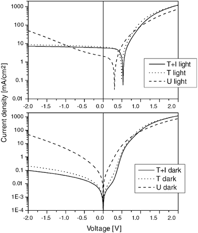 | ||
| Fig. 19 I–V measurements of P3HT ∶ PCBM plastic solar cells under 80 mW cm−2 AM 1.5 solar spectrum simulation (light) and in the dark. The photocurrent and the diode characteristics improved from untreated (U) over thermal annealing (T) to thermal annealing in combination with the application of external voltage (T + I). (Reproduced with permission from reference 25, Copyright 2004, Wiley VCH.) | ||
In a correlated study on the optical properties of similarly prepared P3HT ∶ PCBM devices, the effect of increased absorption due to the postproduction treatments was investigated via optical modeling.58 The absorption in the active layer of the different devices was determined by the reflection spectra. The strongest increase in absorption achieved by the treatments was determined to be about 40% and originated from a red-shift in the polythiophene absorption.58 The calculated absorption compared rather well to the experimentally determined spectral photocurrents exhibiting a maximum of 70%.25,58 These values were in the same range as reported earlier for P3HT ∶ PCBM photodetectors by the Siemens group as well.23 Since the efficiency increase of the treated P3HT ∶ PCBM devices was much higher than 40%, the improved performance can not only be related to improved absorption in the devices. Thus morphological changes must play a role in the charge generation and transport as well.
Dittmer et al. described previously the influence of postproduction annealing on polymer–dye bulk heterojunctions on the device efficiency.59,60 The authors assigned the improved photocurrents to the formation of a network by the dye molecules upon crystallization. As a consequence, the crystalline network provided better percolation resulting in improved charge transport properties for the electrons. Within this section it will become evident that concerning the ability of crystallization spherical fullerenes are comparable to these planar dyes.
Camaioni et al. investigated the effect of a “mild thermal treatment” on the performance of poly(3-alkylthiophene) ∶ fullerene solar cells.24 The authors observed a three to four fold increase in the power conversion efficiency upon annealing at relatively low temperatures (50–60 °C). This improvement has been related to improved order in the film, especially to that of the polythiophene, which is known to crystallize upon thermal annealing61 or chloroform vapor treatment.62 In Fig. 20 the results are summarized for the case of a P3HT ∶ fulleropyrrolidine 3 ∶ 2 solar cell.
 | ||
| Fig. 20 Short circuit photocurrent (upper left), open circuit voltage (upper right), fill factor (lower left) and power conversion efficiency (lower right) of P3HT ∶ fulleropyrrolidine 3 ∶ 2 (by weight) blend solar cells. Full circles mark the parameters measured at the elevated temperature, full triangles denote the parameters after the first heat cycle, and diamonds those after the second heat cycle. (Reproduced from reference 24 with permission, Copyright 2002, Wiley VCH.) | ||
It is noteworthy that the induced changes in the morphology remained after cooling the devices down again (see Fig. 19, triangles and diamonds), i.e. the P3HT ∶ fulleropyrrolidine blend relaxed to an energetically lower lying thermodynamic state and remained there after the first heat cycle.
Chirvase et al. reported recently a comprehensive study on the influence of thermal annealing on the nanomorphology and performance of very similar P3HT ∶ PCBM bulk heterojunction solar cells.27 The authors concluded the red shift in absorption of the annealed devices to result from molecular diffusion of PCBM out of the polythiophene matrix. Furthermore they argued that the growth of PCBM clusters led to the formation of percolation paths and thus improved the photocurrent. An improved ordering of P3HT domains via interchain interactions63 and improved interface properties due to reduced interface defects64 has been proposed earlier as a result of thermal annealing. Chirvase et al identified that thermal annealing of pristine PCBM or P3HT films yielded only slight changes in the absorption, whereas annealing of blends resulted in a large increase of P3HT absorption (see Fig. 21).27
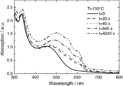 | ||
| Fig. 21 Absorption spectra of a P3HT ∶ PCBM composite film as cast (solid curve) and after four successive thermal annealing steps, as indicated in the legend. The PCBM concentration is 67%. Reprinted with permission from reference 27, Copyright 2004, Institute of Physics Publishing. | ||
The observed growth of large micron-sized PCBM crystal domains was found to depend on the initial concentration of PCBM in the blend as well as on the duration of the annealing process. In Fig. 22 the topography of P3HT ∶ PCBM films with and without aluminium electrode are shown for two different PCBM concentrations (50% and 75%). Clearly the dendritic structures observed for the 75% PCBM concentration are much larger in size than the crystals for 50% PCBM.
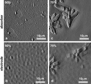 | ||
| Fig. 22 Tapping mode AFM images taken on P3HT ∶ PCBM films without (a, c) and with aluminium top electrode (b, d) at different PCBM concentrations. Large dendritic PCBM crystals are observed for the higher fullerene concentration (c, d). Reprinted with permission from reference 27, Copyright 2004, Institute of Physics Publishing. | ||
Kim et al reported also on the effect of thermal annealing on P3HT ∶ PCBM solar cell device efficiency.28 The authors suggested a vertical phase segregation between P3HT and PCBM to result from the thermal annealing, where P3HT is deposited adjacent to the PEDOT ∶ PSS electrode. Thus the holes could be transported more efficiently to the PEDOT ∶ PSS electrode and electrons directly to the top-aluminium contact, yielding better diode properties.28 In addition the authors investigated the influence of the annealing temperature on the device parameters and found the best results for annealing at 140 °C.
Yang et al. reported on the nanoscale morphology of P3HT ∶ PCBM solar cells using TEM and electron diffraction.29 Upon annealing the blend the authors observed an increase in crystallinity mainly for the P3HT phase but also for the PCBM. The authors observed that due to the annealing the fibrillar P3HT crystals extend their length and new PCBM domains are developed. As a result the charge transport properties will improve for both types of charges due to expansion of the crystalline domains, yielding higher device efficiencies.29Fig. 23 shows the TEM images together with the electron diffraction images for the untreated and the annealed P3HT ∶ PCBM blend.
 | ||
| Fig. 23 TEM images in combination with electron diffraction patterns of untreated (a) and thermally annealed (b) P3HT ∶ PCBM blend films (reproduced from reference 29 with permission). | ||
Remarkably the P3HT backbone was found to be oriented vertical to the P3HT fibrils, thus the π–π stacking direction itself was parallel to the long axis of the P3HT crystals.65 Thus the charge transport will follow the π–π stacking direction and the improved order results in better charge carrier mobilities.
Erb et al. correlated XRD measurements with P3HT ∶ PCBM composite films.66 The authors showed that upon annealing P3HT crystallites of sizes of about 10 nm are grown. The polymer backbone orientation within these crystallites was found to be parallel to the substrate, whereas the side-chains were oriented perpendicular to the substrate (a-axis orientation of P3HT crystallites). No other orientations of P3HT crystals could be observed in the blend films, though all orientations were verified earlier for a powder sample. The XRD signals before and after thermal annealing of P3HT ∶ PCBM composites are shown in Fig. 24.
 | ||
| Fig. 24 X-Ray diffraction diagram (grazing incidence) of P3HT ∶ PCBM composite films deposited on glass/ITO/PEDOT ∶ PSS substrates. (Reproduced with permission from reference 66, Copyright 2005, Wiley VCH.) | ||
Also these authors correlated the increase in device efficiency with an increased crystallinity, but in contrast to Kim et al. they did not detect any PCBM crystals in the blend film.66 Furthermore it could be shown that the earlier observed increase in optical absorption upon annealing can be correlated to the crystallization induced ordering of P3HT in the blends.67
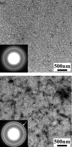
We have shown that upon annealing at relatively high temperatures (150 °C) for sufficiently long times micron-sized PCBM crystals evolve out of MDMO-PPV ∶ PCBM blends and the system is ultimately driven towards complete phase separation between the two constituents.38,71 This has been supported by photoluminescence measurements, since the initially quenched luminescence of the MDMO-PPV recurred after the annealing process.38 AFM measurements revealed some micron-sized aggregates,38 the crystalline structure of which has been identified using TEM in combination with electron diffraction.71 In between these crystallites an amorphous signal was detected, which is reminiscent of the complete amorphous signal obtained on pristine MDMO-PPV films. The TEM results are presented together with the selected area electron diffraction signal in Fig. 25.
 | ||
| Fig. 25 Transmission electron microscopy images of toluene cast MDMO-PPV ∶ PCBM blends before (a) and after 4 hours of annealing at 150 °C (b). The selected area electron diffraction (SAED) signals obtained on crystalline fullerene aggregates (c) and on the amorphous MDMO-PPV (d) are displayed as well. Reprinted from reference 71, Copyright 2005, with permission from Elsevier. | ||
Since it is known that C60 grows in an fcc crystal structure,72 we assumed the same for the PCBM. Based on the hexagonal diffraction signal (Fig. 25c) we calculated a lattice constant of about 14 Å in good agreement with the lattice constant of C60.71,72 Interestingly it seems possible that the comparably small side groups of PCBM still allow the arrangement in such a closed packed order, bearing in mind that the C60 molecule has a size of about 7 Å.
 | ||
| Fig. 26 The polymer-rich region between the PCBM crystallites imaged by tapping mode AFM measurements, after thermal annealing of MDMO-PPV ∶ PCBM 1 ∶ 4 films cast from toluene for 4 hours at different temperatures, is shown. While up to 150 °C polymer nanospheres can be detected, for temperatures considerably larger than 165 °C these spheres are not visible any more and the polymer seems to be molten. Reprinted from reference 54, Copyright 2005, with permission from Elsevier. | ||
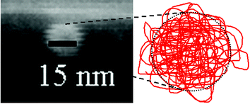
The spherical shape points to a coiled conformation of the polymer. Several polymer nanospheres were measured in magnifications of SEM images. Fig. 27 shows a typical nanosphere with a diameter of about 15 nm together with an illustration for the coiled conformation. Considering a molecular mass of m = 106 u, and a density of ρ = 910 kg m−3 for MDMO-PPV,73 the volume of a single polymer chain becomes approximately Vc = 1.8 × 10⁻²⁴ m3. For a sphere of the same volume the diameter is calculated as approximately 15 nm, and an astonishingly good agreement between the size of one nanosphere and the calculated volume taken up by a single MDMO-PPV chain is found. Note that varying the molecular weight between 2.5 × 10⁵ u and 2.5 × 10⁶ u changes the resulting nanosphere diameter only between 10 to 20 nm.
 | ||
| Fig. 27 Magnification of an SEM cross-sectional measurement: a typical polymer nanosphere radius of 15 nm was found in films cast from chlorobenzene based blends. The conformation of the polymer chain is illustrated in the right side. Reprinted from reference 54, Copyright 2005, with permission from Elsevier. | ||
Thus, whereas the fullerene favors nanocrystalline order, MDMO-PPV exhibits naturally a coiled conformation. This may be a result of minimizing the interfacial area with the surrounding PCBM and points to a repulsive interaction between the two, in agreement with the observed phase separation upon annealing.
Such a coiled conformation also seems possible for P3HT, and indications for a spherical conformation of P3HT polymers have been found using SEM. In Fig. 28 MDMO-PPV ∶ PCBM and P3HT ∶ PCBM chlorobenzene cast blend films are shown for comparison. However, for molecular weights of P3HT at least one order of magnitude lower than for MDMO-PPV, the nanospheres in P3HT ∶ PCBM blends are probably formed out of several entangled polymer chains (compare with reference 50).
 | ||
| Fig. 28 SEM cross-sectional views of MDMO-PPV ∶ PCBM 1 ∶ 2 (a) and regio-regular P3HT ∶ PCBM 1 ∶ 2 (b) blend films cast from chlorobenzene. In both images nanospheres can be found in the active layer. | ||
The difference between the image of spherical P3HT particles and P3HT whiskers or lamellar crystallites can be resolved as follows: the spherical particle remains as a substructure, from which the P3HT lamellar crystallites are subsequently built. This suggestion follows the recently proposed crystallization route of conventional polymers from the melt by Strobl.74 The size of the nanospheres imaged by SEM and the width of the lamellar crystallites imaged by TEM were in both cases around 15 nm and agree well.29
Very high resolution TEM images of P3HT ∶ PCBM blends before and after thermal annealing at 150 °C for 30 min and 2 hours indeed confirm the spherical nanostructure of P3HT on the order of 10 nm (see Fig. 29).32
 | ||
| Fig. 29 High resolution TEM images of regioregular P3HT ∶ PCBM 1 ∶ 0.8 blend films cast from chlorobenzene, (a) as cast, (b) annealed at 150 °C for 30 min and (c) for 2 hours. Clearly visible are the spherical P3HT nanostructures with a size on the order of 10 nm. (Reproduced with permission from reference 32, Copyright 2005, Wiley VCH.) | ||
2.5 Influence of the chemical structure
As mentioned above, the introduction of the more soluble C60 derivative PCBM allowed the incorporation of a larger fraction of fullerenes into polymer–fullerene blend films.5 The same holds for the conjugated polymers, which become only soluble due to side-chain addition. Thus it is clear that the part of the chemical structure that provides the solubility is an important parameter for reaching well-blended bulk heterojunctions of the constituents at the nano scale.Another factor is the chemical compatibility between the polymer and the fullerene itself: since the thermal annealing—required for better efficiency—resulted in a phase separation between P3HT and PCBM, it is obvious that the extent of phase separation upon spin casting must be here smaller than for MDMO-PPV ∶ PCBM blends. Due to the annealing, the PCBM molecules may diffuse and form larger aggregates with an at least partially crystalline structure. Thereby the polymer domains also form a more ordered phase giving crystalline diffraction signals.
Whilst MDMO-PPV ∶ PCBM blend films yielded generally the best results when spin cast from chlorobenzene, this solvent could not deliver similar good results for an MDMO-PPV ∶ C70-PCBM blend.17 Wienk et al. reported that changing the fullerene to C70-PCBM required the use of ortho-dichlorobenzene instead of chlorobenzene to reach a small scale of phase separation. Thus chemical compatibility can be readily tuned by changing the solvent, and needs to be readjusted for every new polymer–fullerene system.
To overcome the large-scale phase separation in P3OT/C60 blends, Camaioni et al. applied plasticizers (e.g. PL1: a poly(3-butyl-co-3,4-dibutylthiophene) copolymer with 50 ∶ 50 ratio between 3-butyl and 3,4-dibutyl thiophenes), to increase the compatibility between the two components.75 Indeed the size of the C60 crystallites was reduced by a large extent and more homogeneous blends resulted. Fig. 30 displays the change in morphology from P3OT/C60 (1 ∶ 1) to P3OT/PL1/C60 (1.5 ∶ 0.5 ∶ 2), obtained by TEM.
 | ||
| Fig. 30 Transmission electron micrographs of P3OT/C60 (1 ∶ 1) (left) and P3OT/plasticizer/C60 (1.5 ∶ 0.5 ∶ 2) (right) blends. Due to the plasticizer the average C60 domain decreased drastically in size. Reprinted from reference 75, Copyright 2002, with permission from Elsevier. | ||
On the other hand, the modification of the polymer chemical structure itself by the insertion of compatibilizing structures into the polymer backbone was recently applied successfully.76 The authors found for polyfluorene copolymers that the insertion of a benzothiadiazole group resulted in a finer intermixing together with PCBM than the corresponding polymers without that group. Therefore this benzothiadiazole group could possibly cause an attractive interaction with the fullerene, which prevents the evolution of large-scale phase separation in the blend.
3. Ternary phase system of polymer, fullerene and solvent
Taking the above mentioned results together allows the conclusion that there is a subtle interplay between many parameters in the ternary system of polymer, fullerene and solvent. Therefore the morphology optimization requires the control of several parameters at the same time: the chemical compatibility between polymer and fullerene, the miscibility and solubility of both in the solvent and appropriate drying behavior at solvent extraction during the film formation process.In Fig. 31 the ternary phase diagram of polymer, solvent and fullerene at a constant temperature T and a constant pressure p is schematically depicted. In the solution only small amounts of polymer and fullerene are present and the solvent can be regarded as a compatibilizer that allows the blending of the two constituents. This can be understood easily, as for very dilute systems polymer and fullerene molecules will not even encounter each other within the solution. The less solvent is present, the e.g. more repulsive interactions between polymer and fullerene will take over. However, since phase separation or spinodal decomposition is a temperature dependent process in time, the mixed state of the polymer–fullerene blend can be frozen in, if the solvent is extracted rapidly enough from the system. Then the system is quenched into a metastable state and dynamically blocked as the molecules are not mobile enough at lower temperatures to proceed with the phase separation. This phase separation can be turned on again upon thermal annealing of the blend, as then the fullerene is activated to diffuse and the polymer chains may reorient and eventually crystallize. If the solvent extraction time is prolonged as in the case of drop cast films, the polymer and fullerene molecules are mobile for a longer time due to the presence of the solvent molecules. This allows the phase separation to proceed and results in larger coarsened domain structures.38,49
 | ||
| Fig. 31 Schematic ternary phase diagram of a polymer–fullerene–solvent system at constant temperature T and constant pressure p. The arrows indicate the direction of increasing concentration, CS,i, CP,i and CF,i are the initial concentrations of solvent, polymer and fullerene in the solution. During film formation a more or less rapid quenching of the solution towards a solid-state blend takes place upon extraction of the solvent. | ||
Considering the fullerene to be less soluble than the polymer in a certain solvent, upon solvent extraction the fullerene component will precipitate earlier into large and pure domains. The onset for fullerene precipitation will be once the system is brought below the solubility limit of the fullerene into the two-phase regime. As the solubility of PCBM is lower for toluene as compared to chlorobenzene, the growth of PCBM clusters commences earlier for toluene cast blends and thus results in larger clusters during the film formation. This has been observed for toluene based MDMO-PPV ∶ PCBM blends and hence indeed the lower solubility of the PCBM in toluene as compared to chlorobenzene could cause the built up of a more coarse nanomorphology.
4. Conclusions
In conclusion, a complex interplay between chemical structure, solubility and compatibility triggers the evolution of the polymer–fullerene blend film nanomorphology during film formation. Due to the complexity, and since the parameters are many, the optimal morphology is in practice explored by engineering, however, increased understanding in this area allows rather direct manipulations in the future. A fundamental difference between amorphous and crystalline polymers was found in the improved morphological stability in blends with fullerenes. And finally, an optimized bulk heterojunction nanomorphology remains an important key for the power conversion efficiency.Acknowledgements
Financial support was partly provided by the German Ministry for Education and Research (BMBF, contract numbers 01SF0026 and 01SF0119). Part of this work was performed within the Christian Doppler Society's dedicated laboratory on Plastic Solar Cells co-funded by Konarka Corporation. HH would like to thank M. Niggemann for the SEM operation, A. Mozer for providing the P3HT ∶ PCBM device, and C. Winder for the help in determining the PCBM solubility.References
- N. S. Sariciftci, L. Smilowitz, A. J. Heeger and F. Wudl, Photoinduced electron transfer from a conducting polymer to buckminsterfullerene, Science, 1992, 258, 1474 CrossRef CAS.
- N. S. Sariciftci, D. Braun, C. Zhang, V. I. Srdanov, A. J. Heeger, G. Stucky and F. Wudl, Semiconducting polymer-buckminsterfullerene heterojunctions: Diodes, photodiodes, and photovoltaic cells, Appl. Phys. Lett., 1993, 62, 585 CrossRef CAS.
- G. Yu and A. J. Heeger, Charge separation and photovoltaic conversion in polymer composites with internal donor/acceptor heterojunctions, J. Appl. Phys., 1995, 78, 4510 CrossRef CAS.
- J. J. M. Halls, C. A. Walsh, N. C. Greenham, E. A. Marseglia, R. H. Friend, S. C. Moratti and A. B. Holmes, Efficient photodiodes from interpenetrating polymer networks, Nature, 1995, 376, 498 CrossRef CAS.
- G. Yu, J. Gao, J. C. Hummelen, F. Wudl and A. J. Heeger, Polymer Photovoltaic Cells: Enhanced Efficiencies via a Network of Internal Donor–Acceptor Heterojunctions, Science, 1995, 270, 1789 CrossRef CAS.
- H. Hoppe and N. S. Sariciftci, in Organic Photovoltaics, ed. S.-S. Sun and N. S. Sariciftci, Taylor & Francis, London, 2005, p. 217 Search PubMed.
- C. Y. Yang and A. J. Heeger, Morphology of composites of semiconducting polymers mixed with C60, Synth. Met., 1996, 83, 85 CrossRef CAS.
- S. E. Shaheen, C. J. Brabec, N. S. Sariciftci, F. Padinger, T. Fromherz and J. C. Hummelen, 2.5% efficient organic plastic solar cells, Appl. Phys. Lett., 2001, 78, 841 CrossRef CAS.
- C. J. Brabec, N. S. Sariciftci and J. C. Hummelen, Plastic Solar Cells, Adv. Funct. Mater., 2001, 11, 15 CrossRef CAS.
- J. Gao, F. Hide and H. Wang, Efficient photodetectors and photovoltaic cells from composites of fullerenes and conjugated polymers: photoinduced electron transfer, Synth. Met., 1997, 84, 979 CrossRef CAS.
- S. E. Shaheen, R. Radspinner, N. Peyghambarian and G. E. Jabbour, Fabrication of bulk heterojunction plastic solar cells by screen printing, Appl. Phys. Lett., 2001, 79, 2996 CrossRef CAS.
- J. Liu, Y. Shi and Y. Yang, Solvation-Induced Morphology Effects on the Performance of Polymer-Based Photovoltaic Devices, Adv. Funct. Mater., 2001, 11, 420 CrossRef CAS.
- J. M. Kroon, M. M. Wienk, W. J. H. Verhees and J. C. Hummelen, Accurate efficiency determination and stability studies of conjugated polymer/fullerene solar cells, Thin Solid Films, 2002, 403–404, 223 CrossRef CAS.
- T. Munters, T. Martens, L. Goris, V. Vrindts, J. Manca, L. Lutsen, W. D. Ceunick, D. Vanderzande, L. D. Schepper, J. Gelan, N. S. Sariciftci and C. J. Brabec, A comparison between state-of-the-art ‘gilch’ and ‘sulfinyl’ synthesised MDMO-PPV/PCBM bulk hetero-junction solar cells, Thin Solid Films, 2002, 403–404, 247 CrossRef CAS.
- T. Aernouts, W. Geens, J. Portmans, P. Heremans, S. Borghs and R. Mertens, Extraction of bulk and contact components of the series resistance in organic bulk donor–acceptor-heterojunctions, Thin Solid Films, 2002, 403–404, 297 CrossRef CAS.
- V. Dyakonov, The polymer–fullerene interpenetrating network: one route to a solar cell approach, Physica E (Amsterdam), 2002, 14, 53 CrossRef CAS.
- M. M. Wienk, J. M. Kroon, W. J. H. Verhees, J. Knol, J. C. Hummelen, P. A. van Hall and R. A. J. Janssen, Efficient Methano[70]fullerene/MDMO-PPV Bulk Heterojunction Photovoltaic Cells, Angew. Chem., Int. Ed., 2003, 42, 3371 CrossRef CAS.
- I. Riedel, J. Parisi, V. Dyakonov, L. Lutsen, D. Vanderzande and J. C. Hummelen, Effect of Temperature and Illumination on the Electrical Characteristics of Polymer-Fullerene Bulk-Heterojunction Solar Cells, Adv. Funct. Mater., 2004, 14, 38 CrossRef CAS.
- A. Mozer, P. Denk, M. Scharber, H. Neugebauer, N. S. Sariciftci, P. Wagner, L. Lutsen and D. Vanderzande, Novel Regiospecific MDMO-PPV Copolymer with Improved Charge Transport for Bulk Heterojunction Solar Cells, J. Phys. Chem. B, 2004, 108, 5235 CrossRef CAS.
- M. Al-Ibrahim, H. K. Roth and S. Sensfuss, Efficient large-area polymer solar cells on flexible substrates, Appl. Phys. Lett., 2004, 85, 1481 CrossRef CAS.
- L. S. Roman, O. Inganäs, T. Granlund, T. Nyberg, M. Svensson, M. R. Andersson and J. C. Hummelen, Trapping Light in Polymer Photodiodes with Soft Embossed Gratings, Adv. Mater., 2000, 12, 189 CrossRef CAS.
- D. Gebeyehu, C. J. Brabec, F. Padinger, T. Fromherz, J. C. Hummelen, D. Badt, H. Schindler and N. S. Sariciftci, The interplay of efficiency and morphology in photovoltaic devices based on interpenetrating networks of conjugated polymers with fullerenes, Synth. Met., 2001, 118, 1 CrossRef CAS.
- P. Schilinsky, C. Waldauf and C. J. Brabec, Recombination and loss analysis in polythiophene based bulk heterojunction photodetectors, Appl. Phys. Lett., 2002, 81, 3885 CrossRef CAS.
- N. Camaioni, G. Ridolfi, G. Casalbore-Miceli, G. Possamai and M. Maggini, The Effect of a Mild Thermal Treatment on the Performance of Poly(3-alkylthiophene)/Fullerene Solar Cells, Adv. Mater., 2002, 14, 1735 CrossRef CAS.
- F. Padinger, R. S. Rittberger and N. S. Sariciftci, Effects of Postproduction Treatment on Plastic Solar Cells, Adv. Funct. Mater., 2003, 13, 1 CrossRef CAS.
- C. Waldauf, P. Schilinsky, J. Hauch and C. J. Brabec, Material and device concepts for organic photovoltaics: towards competitive efficiencies, Thin Solid Films, 2004, 451–452, 503 CrossRef CAS.
- D. Chirvase, J. Parisi, J. C. Hummelen and V. Dyakonov, Influence of nanomorphology on the photovoltaic action of polymer-fullerene composites, Nanotechnology, 2004, 15, 1317–1323 CrossRef CAS.
- Y. Kim, S. A. Choulis, J. Nelson, D. D. C. Bradley, S. Cook and J. R. Durrant, Device annealing effect in organic solar cells with blends of regioregular poly(3-hexylthiophene) and soluble fullerene, Appl. Phys. Lett., 2005, 86, 063502 CrossRef.
- X. Yang, J. Loos, S. C. Veenstra, W. J. H. Verhees, M. M. Wienk, J. M. Kroon, M. A. J. Michels and R. A. J. Janssen, Nanoscale Morphology of High-Performance Polymer Solar Cells, Nano Lett., 2005, 5, 579 CrossRef CAS.
- M. Al-Ibrahim, O. Ambacher, S. Sensfuss and G. Gobsch, Effects of solvent and annealing on the improved performance of solar cells based on poly(3-hexylthiophene):Fullerene, Appl. Phys. Lett., 2005, 86, 201120 CrossRef.
- M. Reyes-Reyes, K. Kim and D. L. Carrolla, High-efficiency photovoltaic devices based on annealed poly(3-hexylthiophene) and 1-(3-methoxycarbonyl)-propyl-1-phenyl-(6,6)C61 blends, Appl. Phys. Lett., 2005, 87, 083506 CrossRef.
- W. Ma, C. Yang, X. Gong, K. Lee and A. J. Heeger, Thermally Stable, Efficient Polymer Solar Cells with Nanoscale Control of the Interpenetrating Network Morphology, Adv. Funct. Mater., 2005, 15, 1617 CrossRef CAS.
- M. Svensson, F. Zhang, S. C. Veenstra, W. J. H. Verhees, J. C. Hummelen, J. M. Kroon, O. Inganäs and M. R. Andersson, High-Performance Polymer Solar Cells of an Alternating Polyfluorene Copolymer and a Fullerene Derivative, Adv. Mater., 2003, 15, 988 CrossRef CAS.
- T. Yohannes, F. Zhang, M. Svensson, J. C. Hummelen, M. R. Andersson and O. Inganäs, Polyfluorene copolymer based bulk heterojunction solar cells, Thin Solid Films, 2004, 449, 152 CrossRef CAS.
- H. Hoppe, D. A. M. Egbe, D. Mühlbacher and N. S. Sariciftci, Photovoltaic action of conjugated polymer/fullerene bulk heterojunction solar cells using novel PPE-PPV-copolymers, J. Mater. Chem., 2004, 14, 3461 Search PubMed.
- M. Al-Ibrahim, A. Konkin, H.-K. Roth, D. A. M. Egbe, E. Klemm, U. Zhokhavets, G. Gobsch and S. Sensfuss, PPE-PPV copolymers: optical and electrochemical characterization, comparison with MDMO-PPV and application in flexible polymer solar cells, Thin Solid Films, 2005, 474, 201 CrossRef CAS.
- J. C. Hummelen, B. W. Knight, F. LePeq, F. Wudl, J. Yao and C. L. Wilkins, Preparation and Characterization of Fulleroid and Methanofullerene Derivatives, J. Org. Chem., 1995, 60, 532 CrossRef CAS.
- H. Hoppe, M. Niggemann, C. Winder, J. Kraut, R. Hiesgen, A. Hinsch, D. Meissner and N. S. Sariciftci, Nanoscale morphology of conjugated polymer/fullerene based bulk-heterojunction solar cells, Adv. Funct. Mater., 2004, 14, 1005 CrossRef CAS.
- T. Martens, J. D'Haen, T. Munters, Z. Beelen, L. Goris, J. Manca, M. D'Olieslaeger, D. Vanderzande, L. D. Schepper and R. Andriessen, Disclosure of the nanostructure of MDMO-PPV ∶ PCBM bulk heterojunction organic solar cells by a combination of SPM and TEM, Synth. Met., 2003, 138, 243 CrossRef CAS.
- T. Martens, Z. Beelen, J. D'Haen, T. Munters, L. Goris, J. Manca, M. D'Olieslaeger, D. Vanderzande, L. D. Schepper and R. Andriessen, Morphology of MDMO-PPV ∶ PCBM bulk hetero-junction organic solar cells studied by AFM, KFM and TEM, Proc. SPIE-Int. Soc. Opt. Eng., 2003, 4801, 40 CAS.
- H. Hoppe, T. Glatzel, M. Niggemann, A. Hinsch, M. C. Lux-Steiner and N. S. Sariciftci, Kelvin Probe Force Microscopy Study on Conjugated Polymer/Fullerene Bulk Heterojunction Organic Solar Cells, Nano Lett., 2005, 5, 269 CrossRef CAS.
- T. Glatzel, H. Hoppe, N. S. Sariciftci, M. C. Lux-Steiner and M. Komiyama, Kelvin Probe Force Microscopy Study on Conjugated Polymer/Fullerene Organic Solar Cells, Jpn. J. Appl. Phys., 2005, 44, 5370 CrossRef CAS.
- T. Röder, H.-S. Kitzerow and J. C. Hummelen, Morphology and fluorescence quenching in photovoltaic samples containing fullerene and poly(p-phenylene-vinylene) derivatives, Synth. Met., 2004, 141, 271 CrossRef CAS.
- C. R. McNeill, H. Frohne, J. L. Holdsworth, J. E. Furst, B. V. King and P. C. Dastoor, Direct Photocurrent Mapping of Organic Solar Cells Using a Near-Field Scanning Optical Microscope, Nano Lett., 2004, 4, 219 CrossRef CAS.
- C. R. McNeill, H. Frohne, J. L. Holdsworth and P. C. Dastoor, Direct influence of morphology on current generation in conjugated polymer ∶ methanofullerene solar cells measured by near-field scanning photocurrent microscopy, Synth. Met., 2004, 147, 101 CrossRef CAS.
- K. O. Sylvester-Hvid, S. Rettrup and M. A. Ratner, Two-Dimensional Model for Polymer-Based Photovoltaic Cells: Numerical Simulations of Morphology Effects, J. Phys. Chem. B, 2004, 108, 4296 CrossRef CAS.
- F. Wudl, P.-M. Allemand, G. Srdanov, Z. Ni and D. McBranch, in Materials for Nonlinear Optics: Chemical Perspectives, ed. S. R. Marder, J. E. Sohn and G. D. Stucky, American Chemical Society, Washington DC, 1991, p. 683 Search PubMed.
- M. T. Rispens, A. Meetsma, R. Rittberger, C. J. Brabec, N. S. Sariciftci and J. C. Hummelen, Influence of the solvent on the crystal structure of PCBM and the efficiency of MDMO-PPV ∶ PCBM ‘plastic’ solar cells, Chem. Commun., 2003, 2116 RSC.
- T. Martens, J. D'Haen, T. Munters, L. Goris, Z. Beelen, J. Manca, M. D'Olieslaeger, D. Vanderzande, L. D. Schepper and R. Andriessen, The influence of the microstructure upon the photovoltaic performance of MDMOPPV ∶ PCBM bulk hetero-junction organic solar cells, presented at the MRS Spring Meeting, San Francisco, 2002, Materials Research Society, P7.11.1.
- B. Wessling, From conductive polymers to organic metals, Chem. Innovation, 2001, 31, 34 CAS.
- J. K. J. van Duren, X. Yang, J. Loos, C. W. T. Bulle-Lieuwma, A. B. Sieval, J. C. Hummelen and R. A. J. Janssen, Relating the Morphology of Poly(p-phenylene vinylene)/Methanofullerene Blends to Solar-Cell Performance, Adv. Funct. Mater., 2004, 14, 425 CrossRef CAS.
- P. Peumans, A. Yakimov and S. R. Forrest, Small molecular weight organic thin-film photodetectors and solar cells, J. Appl. Phys., 2003, 93, 3693 CrossRef CAS.
- H. Hoppe, N. Arnold, D. Meissner and N. S. Sariciftci, Modeling the optical absorption within conjugated polymer/fullerene-based bulk-heterojunction organic solar cells, Sol. Energy Mater. Sol. Cells, 2003, 80, 105 CrossRef CAS.
- H. Hoppe, T. Glatzel, M. Niggemann, W. Schwinger, F. Schaeffler, A. Hinsch, M. C. Lux-Steiner and N. S. Sariciftci, Efficiency limiting morphological factors of MDMO-PPV ∶ PCBM plastic solar cells, Thin Solid Films, 2005 Search PubMed , in press.
- A. Haugeneder, M. Neges, C. Kallinger, W. Spirkl, U. Lemmer, J. Feldmann, U. Scherf, E. Harth, A. Gügel and K. Müllen, Exciton diffusion and dissociation in conjugated polymer/fullerene blends and heterostructures, Phys. Rev. B, 1999, 59, 15346 CrossRef CAS.
- X. Yang, J. K. J. van Duren, R. A. J. Janssen, M. A. J. Michels and J. Loos, Morphology and Thermal Stability of the Active Layer in Poly(p-phenylenevinylene)/Methanofullerene Plastic Photovoltaic Devices, Macromolecules, 2004, 37, 2151 CrossRef CAS.
- H. Becker, Frankfurt, Germany, 2004, private communication.
- H. Hoppe, N. Arnold, D. Meissner and N. S. Sariciftci, Modeling of optical absorption in conjugated polymer/fullerene bulk-heterojunction plastic solar cells, Thin Solid Films, 2004, 451–452, 589 CrossRef CAS.
- J. J. Dittmer, E. A. Marseglia and R. H. Friend, Electron Trapping in Dye/Polymer Blend Photovoltaic Cells, Adv. Mater., 2000, 12, 1270 CrossRef CAS.
- J. J. Dittmer, R. Lazzaroni, P. Leclere, P. Moretti, M. Granström, K. Petritsch, E. A. Marseglia, R. H. Friend, J. L. Bredas, H. Rost and A. B. Holmes, Crystal network formation in organic solar cells, Sol. Energy Mater. Sol. Cells, 2000, 61, 53 CrossRef CAS.
- Y. Zhao, G. X. Yuan, P. Roche and M. Leclerc, Polymer, 1995, 36, 2211 CrossRef CAS.
- M. Berggren, G. Gustafsson, O. Inganas, M. R. Andersson, O. Wennerstrom and T. Hjertberg, Appl. Phys. Lett., 1994, 65, 1489 CrossRef CAS.
- P. J. Brown, D. S. Thomas, A. Köhler, J. Wilson, J. S. Kim, C. Ramsdale, H. Sirringhaus and R. H. Friend, Effect of interchain interactions on the absorption and emission of poly(3-hexylthiophene), Phys. Rev. B, 2003, 67, 064203 CrossRef.
- T. Ahn and H. L. Sein-HoHa, Appl. Phys. Lett., 2002, 80, 392 CrossRef CAS.
- K. J. Ihn, J. Moulton and P. Smith, Whiskers of poly(3-alkylthiophene)s, J. Polym. Sci., Part B: Polym. Phys., 1993, 31, 735 CrossRef CAS.
- T. Erb, U. Zhokhavets, G. Gobsch, S. Raleva, B. Stühn, P. Schilinsky, C. Waldauf and C. J. Babec, Correlation Between Structural and Optical Properties of Composite Polymer Films for Organic Solar Cells, Adv. Funct. Mater., 2005, 15, 1193 CrossRef CAS.
- T. Erb, U. Zhokhavets, H. Hoppe, G. Gobsch, M. Al-Ibrahim and O. Ambacher, Absorption and crystallinity of Poly(3-hexylthiophene)/fullerene blends in dependence on annealing temperature, Thin Solid Films, 2005 Search PubMed accepted.
- X. Yang, J. K. J. van Duren, M. T. Rispens, J. C. Hummelen, R. A. J. Janssen, M. A. J. Michels and J. Loos, Crystalline Organization of a Methanofullerene as Used for Plastic Solar-Cell Applications, Adv. Mater., 2004, 16, 802 CrossRef CAS.
- S. Schuller, P. Schilinsky, J. Hauch and C. J. Brabec, Determination of the degradation constant of bulk heterojunction solar cells by accelerated lifetime measurements, Appl. Phys. A: Mater. Sci. Process., 2004, 79, 37 Search PubMed.
- M. Drees, H. Hoppe, C. Winder, H. Neugebauer, N. S. Sariciftci, W. Schwinger, F. Schäffler, C. Topf, M. C. Scharber, Z. Zhu and R. Gaudiana, Stabilization of the nanomorphology of polymer/fullerene “bulk heterojunction” blends using a novel polymerizable fullerene derivative, J. Mater. Chem., 2005, 15 10.1039/b505361g.
- H. Hoppe, M. Drees, W. Schwinger, F. Schäffler and N. S. Sariciftci, Nano-Crystalline Fullerene Phases in Polymer/Fullerene Bulk-Heterojunction Solar Cells: A Transmission Electron Microscopy Study, Synth. Met., 2005, 152, 117 CrossRef CAS.
- P. A. Heiney, J. E. Fischer, A. R. McGhie, W. J. Romanow, A. M. Denenstein, J. P. McCauley, Jr., A. B. Smith and D. E. Cox, Orientational ordering transition in solid C60, Phys. Rev. Lett., 1991, 66, 2911 CrossRef CAS.
- C. W. T. Bulle-Lieuwma, W. J. H. van Gennip, J. K. J. van Duren, P. Jonkheijm, R. A. J. Janssen and J. W. Niemantsverdriet, Characterization of polymer solar cells by TOF-SIMS depth profiling, Appl. Surf. Sci., 2003, 203–204, 547 CrossRef CAS.
- G. Strobl, From the melt via mesomorphic and granular crystalline layers to lamellar crystallites: A major route followed in polymer crystallization?, Eur. Phys. J. E, 2000, 3, 165 CrossRef CAS.
- N. Camaioni, M. Catellani, S. Luzzati and A. Migliori, Morphological characterization of poly(3-octylthiophene) ∶ plasticizer ∶ C60 blends, Thin Solid Films, 2002, 403–404, 489 CrossRef CAS.
- C. M. Björström, E. Moons and K. O. Magnusson, Control of phase separation in blends of polyfluorene (co)polymers and the C60-derivative PCBM, Synth. Met., 2005, 152, 109 CrossRef CAS.
Footnote |
| † New address: Institute of Physics, TU Ilmenau, Germany. E-mail: harald.hoppe@tu-ilmenau.de |
| This journal is © The Royal Society of Chemistry 2006 |