New electrodes for old: from carbon nanotubes to edge plane pyrolytic graphite†
Craig E.
Banks
and
Richard G.
Compton
*
Physical and Theoretical Chemistry Laboratory, University of Oxford, South Parks Road, Oxford, UK OX1 3XZ. E-mail: Richard.Compton@chem.ox.ac.uk; Fax: +44 (0)1865 275410; Tel: +44 (0)1865 275413
First published on 28th November 2005
Abstract
Different types of carbon based electrodes have emerged over the last few years, significantly changing the scope and sensitivity of electroanalytical methods for the measurement of diverse targets from metal ions through gases to biological markers. This Highlight article shows how the use of carbon nanotube modified electrodes has led to a fundamental understanding of the location and nature of electron transfer processes on graphitic electrodes and to the realisation that edge plane pyrolytic graphite may represent, at present, an optimal electrode material of this type for electroanalysis.
Introduction
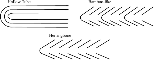
Since the re-discovery of carbon nanotubes (CNTs) in 1991, (Box 1) they have become widely exploited in electroanalysis. This highlight considers why and addresses current and future directions including graphite electrodes now considered to be superior in the electroanalytical context. CNTs are assigned into two classes: single walled (SWCNTs) and multi-wall carbon nanotubes (MWCNTs). The former consist of a single graphite sheet rolled flawless producing a tube diameter of 1–2 nm while the latter comprise several concentric tubes fitted one inside the other. There are a number of morphological variations of the latter including “hollow-tube”, “herringbone” or “bamboo-like” MWCNTs (Box 2).1
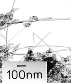
Box 1: Discovery of carbon nanotubesIn 1978 Wiles and Abrahamson observed a thick mat of fine fibres and crystallites on graphite anodes following low current arc operation in nitrogen at atmospheric pressure.2,3 Fibres ranging in diameter from 4 nm up to 100 nm (TEM shown) with lengths up to 15 micrometres were found. These fibres consisted of wrapped graphitic basal layers with a hollow core. The authors noted that the basal layer spacing was distorted from the normal graphite spacing. These fibres are commonly known today as carbon nanotubes. However the term ‘carbon nanotube’ was not coined until they were re-discovered by Iijima in 1991.4 |
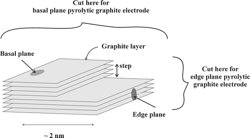
Box 2: Carbon based electrodesEdge plane and basal plane pyrolytic graphite electrodes are fabricated from highly ordered pyrolytic graphite (HOPG). The basal plane surface of an HOPG electrode consists of layers of graphite which lie parallel to the surface and with an interlayer spacing of 3.35 Å. Surface defects occur in the form of steps exposing the edges of the graphite layers. Due to the nature of the chemical bonding in graphite, the two planes, edge and basal, exhibit completely different electrochemical properties. For electrochemistry the edge plane exhibits considerably faster electrode kinetics in comparison with the basal plane. This means that in many instances an electrode consisting entirely of edge plane viz. an edge plane pyrolytic graphite electrode will show a nearly reversible voltammogram while an electrode consisting mainly of basal plane will show irreversible behaviour depending highly on the amount of edge present.
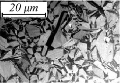
One other form of carbon based electrode is boron-doped diamond. This consists of diamond in which approximately one atom in a thousand has been replaced by boron giving a material with metallic conductivity. An SEM image is shown of a commercial BDD electrode. |
In the hollow tube variation the axis of the graphite planes are parallel to the axis of the CNT. In the herringbone variant the graphite planes are formed at an angle to the axis of the tube. Finally bamboo MWCNTs are similar to herringbone except that the CNTs are periodically closed along the length of the tube into compartments rather like bamboo. This has been likened to a ‘stack of paper cups fitted one inside the other’. The difference between hollow-tube and herringbone and bamboo-like MWCNTs are that a proportionally higher number of edge-plane-like defect sites occur on herringbone and bamboo variants than hollow-tube MWCNTs; this is because in these two cases the plane of the graphite sheets are at an angle to the axis of the tube requiring a high proportion of the graphite sheets to terminate at the surface of the tube. As we will show in this highlight article CNTs have two distinct possible reactive sites; these are edge plane like sites/defects and basal plane sites which occur on the side walls of the CNTs. The terms ‘edge plane’ and ‘basal plane’ are in comparison with the structure of highly ordered pyrolytic graphite (Box 2).
Modified electrodes as electrocatalysts
A common current fad amongst electroanalysts seeking new electrocatalytic surfaces is to modify a suitable electrode substrate, but usually glassy carbon, (Box 2) with a film or layer of CNTs. In fact the number of papers reporting the use of carbon nanotubes as electrodes since Britto's5 first example in 1996 (Box 3) increased slowly over a few years before exploding around 2002. Currently there are literally hundreds of papers involving the use of CNT modified electrodes in electroanalysis: Table 1 highlights a selection of different analytes that have been reported. The claimed benefits of using CNT modified electrodes include low detection limits, increased sensitivity, decreased overpotentials and resistance to surface fouling.6
Box 3: The original carbon nanotube modified experimentThe first group to report the use of carbon nanotubes in electro-analysis was Britto and co-workers in 1996.5 Using a carbon nanotube paste electrode with bromoform as the binder, the electrochemical oxidation of dopamine was explored. The concept of a carbon nanotube paste electrode was later readapted by Valentini et al.7 However the explosion of interest in carbon nanotubes in the early 21st century for use in electro-analysis can be traced back to the work pioneered by Professor Joe Wang, whilst at New Mexico State University, USA who observed the low-potential stable NADH detection at a carbon-nanotube-modified glassy carbon electrode.8 His paper already has over 100 citations, the chemist's equivalent of a Golden Disc Award! |
| Analyte | Support | Electrocatalytic | LOD | Reference |
|---|---|---|---|---|
| Abbreviations: LOD: limit of detection (based on three sigma); GC: glassy carbon electrode; PE: paste electrode; [A]: not specified, but is based on lowest addition; [B]: unknown; [C]: carbon nanotube array. | ||||
| NADH | GC | GC | 0.1 mM [A] | 8 |
| Hydrogen sulfide | GC | GC | 0.3 µM | 9 |
| Morphine | GC | GC | 0.2 µM | 10 |
| Brucine | GC | GC | 0.2 µM | 11 |
| Amitrole | PE | [B] | 0.57 µM | 12 |
| Cytochrome c | GC | GC | 10 µM | 13 |
| Tinidazole | GC | GC/bare graphite | 10 nM | 14 |
| Galactose | GC | GC | 10 µM | 15 |
| Glucose | GC | GC | 1 µM | 16 |
| Nitric oxide | GC | GC | 80 nM | 17 |
| Cadmium | [C] | GC | 7.1 nM | 18 |
| Insulin | GC | GC | 14 nM | 19 |
| Catechol | GC | GC | 10 µM | 20 |
| Uric acid | GC | GC | 0.1 µM | 21 |
In 2004 we explored the electro-reduction of ferricyanide and the oxidations of NADH, epinephrine and nor-epinephrine22 using MWCNT modified basal plane pyrolytic graphite electrodes (BPPG, see Box 2) which were prepared via either abrasive or film modification. The former involves gently rubbing a BPPG electrode on a fine quality filter paper containing the desired CNTs, while the latter was the method for making CNT modified electrodes pioneered by Wang and co-workers.8 This requires dispersing the desired CNTs into an organic solvent which is then pippetted onto a suitable electrode substrate (usually GC) and allowed to volatilize leaving a CNT ‘film’ or dispersion.
With the CNT modified electrode we observed reduced peak-to-peak separations and enhanced voltammetric currents in comparison with the unmodified underlying electrode (BPPG) suggesting that the claimed electrocatalytic properties for CNTs reported in the literature were indeed true. However, an obvious ‘control’ experiment to verify this electrocatalytic behavior involved the ‘modification’ of a BPPG electrode with micron sized graphite powder via film and abrasive attachment and this revealed that similar catalytic behaviour was observed without the presence of any nanotubes!22 Clearly claims for “electrocatalytic properties” of CNTs need to be more cautiously approached.22
In a subsequent publication23 we addressed the question as to why the CNTs were catalytic and provided definitive evidence for the electrocatalytic properties of CNTs. The reduction of the one electron aqueous redox probe, ferricyanide was explored at a CNT film modified BPPG electrode and compared with a bare BPPG electrode. In the former case peak-to-peak separations of 58 mV and 350 mV were observed respectively; the peak-to-peak separation is an indication of the heterogeneous charge transfer kinetics showing that in this case, the CNTs exhibit fast electron transfer.23
Next an edge plane pyrolytic graphite electrode (EPPG) was explored. EPPG electrodes are fabricated by taking a piece of high quality highly ordered pyrolytic graphite (HOPG) and cutting the desired electrode geometry such that the layers of graphite lie perpendicular to the surface; conversely BPPG electrodes are produced by cutting the electrode geometry such that the graphite layers lie parallel to the surface (Box 2).
Returning to the voltammetry of ferricyanide at the EPPG electrode, a peak-to-peak separation of 78 mV was observed suggesting that the electrochemical reaction occurs with a not dissimilar rate constant as at the carbon nanotube modified surface. Note that the slight difference in the peak-to-peak separation of the CNTs compared to that of the EPPG is probably reflective of the slight impurities of basal plane in the EPPG electrode. A catalytic response was also seen for the electrochemical oxidation of epinephrine where identical responses were obtained at both the CNT modified electrode and the EPPG; again slow electrode kinetics were observed at a bare BPPG electrode. Indeed it has been well documented that the electrode kinetics at EPPG electrodes are at least three times faster than at BPPG electrodes1 but seemingly this was the first comparative approach to provide evidence for electrode kinetic enhancements at CNTs.
The BPPG electrode is prepared by the cellotape method22—a strip of tape is pressed onto the surface and removed along with a top layer leaving a new, clean surface—using HOPG. This results in a low proportion of edge plane sites/defects and a high amount of basal plane sites such that when examined in various redox probes it will exhibit slow heterogeneous electron transfer.24 We have shown that by abrasively modifying a BPPG, for example by polishing with alumina particles, the electrode surface can be roughened. Edge plane sites/defects are consequently introduced on the electrode surface resulting in faster electron transfer occurring to the point that after roughening for ca. only a minute a nearly identical response to that of the EPPG electrode can be observed. This clearly shows that edge plane sites are the dominant sites at which fast electron transfer occurs.25
The above experiments suggested by comparison of CNTs with BPPG and EPPG show that edge plane like sites, which in CNTs occur at the ends and along the tube axis (where graphite sheets terminate at the surface of the tube) are likely to be the reason why nanotubes exhibit fast heterogeneous charge transfer and explains why they have been reported as ‘electrocatalytic’ widely in the electrochemical literature.
Definitive evidence for the role of edge plane sites in the electrochemistry of graphite surfaces was provided by two further conclusive experiments using highly ordered pyrolytic graphite where the distance between the step sites is unusually large and can be as much as 5 to 10 microns on suitably prepared or handled surfaces.
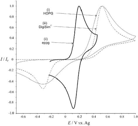
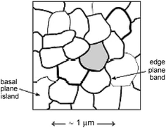
First the voltammetry of simple outer sphere redox couple such as Fe(CN)63−/4− was examined. The shape and the size of the voltammograms (Box 4) seen is quite inconsistent with that expected for linear diffusion to a macroelectrode, in other words what would be expected if all the electrode surface was uniformly active in the electrolysis. Rather the unusual and characteristic voltammograms were consistent with a model in which the electrode surface acted, in effect, as an “array of microband electrodes” in which electrolytic currents flowed only at the microbands and not at all in the zones between them. In the context of HOPG the microbands are the edge plane steps and the basal plane terraces are the voltammetrically inert material in between.24,26
Box 4: Heterogeneous electrode surfaces: understanding the site of electrocatalytic action via simulationsThe figure illustrates a typical cyclic voltammogram for the oxidation of 1 mM ferricyanide in aqueous 1 M KCl, recorded at (i) a basal plane HOPG electrode and (ii) an edge-plane pyrolytic graphite electrode. Overlaid as a dashed curve, (iii), is the simulated ‘linear diffusion only’ voltammogram that best fits the experimental HOPG voltammograms. This simulation assumes all parts of the electrode are uniformly active. The figure illustrates the two main characteristics of HOPG voltammetry. First there is a significant increase in the peak to peak separation over the EPPG voltammogram. Second the fit to a ‘linear diffusion only’ simulation is poor especially in the return scan where a significantly lower back peak current than expected is observed. The correct voltammetric shape was corrected and quantitatively simulated1 by considering the surface as schematically depicted in the figure below. In this the edge plane ‘bands’ are concluded to be exclusively the sites of electrocatalysis whereas the basal plane ‘islands’ are electrocatalytically inert. The surface thus behaves as a random array of microband electrodes which can be shown to produce exactly the voltammetric characteristics shown by HOPG surfaces. |
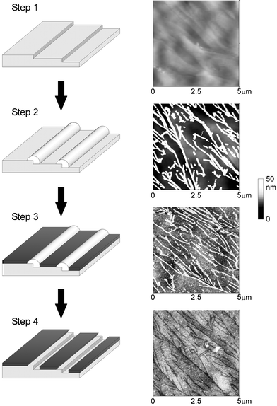
Box 5: NanotrenchesThe key nanochemical experiment in showing that a HOPG surface behaved electrochemically as a random array of microbands (the edge plane steps) separated by essentially voltammetrically inert material (the basal plane terraces) was achieved by selectively blocking the HOPG surface so that the basal plane areas were fully covered with a layer of polymer whilst the edge plane defects were exposed and located at the bottom of the ‘nanotrenches’ the sides of which are formed by the polymer layers on top of the basal planes either side of the edge plane site (step). The array of nanotrenches was formed via the sequence shown with atomic force microscopy imaging (shown) at every stage.First the bare surface was imaged (step 1), then “nanowires” of MoO2 were electrodeposited along the edge plane steps (step 2). The entire surface was then covered with polymer (step 3). Finally acid treatment dissolved the nanowires and the polymer above the wire leaving the polymer covered the basal plane terraces and hence producing an array of nanotrenches. The nanotrench arrays showed nearly identical voltammetry to the initial bare surface, confirming that electrocatalytic activity on the latter is confined to the edge plane sites with the basal plane terraces effectively inert.27 |
The second experiment in defining the site of electron transfer as being the edge plane sites was carried out using atomic force microscopy in conjugation with voltammetric surface of modified HOPG surface (Box 5). In particular the cyclic voltammetric response of HOPG to various model redox couples was essentially unchanged when the basal plane terraces—but not the edge plane steps—were covered with a thick layer of polymer. This confirmed that the terraces were effectively voltammetrically inert and that measurable levels of electron transfer were confined to the edge plane step defects.27
Edge plane pyrolytic graphite electrode as comparable to CNT modified electrodes
In the above we have shown i) that CNT reactivity is solely due to edge plane sites/defects and ii) the concept that electro-reactivity of carbon based electrodes is due to edge plane sites/defects which are the key to fast heterogeneous charge transfer. Given the structure of MWCNTs it is easy to see why they are highly desirable as electrode substrates modified for use in electroanalysis. However it is logical to predict that it should be possible to replace ‘single shot’ carbon nanotube modified electrodes with re-useable edge plane pyrolytic graphite electrodes for routine use in electroanalysis; it was this we first explored via the quantification of thiol moieties.28The quantification of thiols is an important task within the biomedical community since they are biomarkers for a wide range of diseases and their relevant levels in the body are indicative of a range of illnesses. A vast literature using electrochemical methods based on indirect detection via the use of mediators exists since a major problem with the direct electrochemical detection of thiol moieties is that a large oxidative overpotential is required with uncertainty arising from discriminating the analytical signals from solvent breakdown; thus a sensitive technique which occurs far away from solvent breakdown would be highly advantageous.
Consequently we explored an EPPG electrode28 for the electroanalytical determination of homocysteine, N-acetylcysteine, cysteine and glutathione. The electrochemical oxidation of homocysteine in 0.1 M phosphate buffer solution (pH 7) was studied at boron-doped diamond (BDD, see Box 2), glassy carbon, EPPG and BPPG electrodes and a carbon nanotube film modified BPPG electrode. For the BPPG electrode a high background current was observed with no appreciable oxidation waves seen in the potential range studied, while for BDD a small oxidation wave was observed with a large background current. The response of a glassy carbon electrode showed that while the background current is slightly lower than that seen at the BPPG electrode, again no oxidation wave was observed. Last the voltammetric response of the carbon nanotube film modified BPPG electrode revealed a small oxidation wave where a point of inflection was barely visible in the vicinity of ca. +0.64 V (vs. SCE).28 In comparison to all the poor responses observed above, the EPPG electrode exhibited a large and easily quantifiable signature at ca. +0.66 V (vs. SCE) demonstrating a significant reduction in the overpotential in comparison with the other commonly used electrode substrates while also exhibiting an enhanced signal-to-noise ratio.28
The detection limit and analytical efficiency was examined for the range of thiols studied using the EPPG electrode where low micromolar detection limits were observed. This was also extended to examining the determination of cysteine in a growth tissue media containing a high number of common biological interferences with excellent results; clearly the advantageous properties of this electrode for thiol determination lie in its excellent catalytic activity, sensitivity and simplicity, suggesting an attractive alternative to CNT modified electrodes.28
We have further explored the sensing capabilities of EPPG electrodes in the detection of nitrogen dioxide.29 Commercial sensors of this highly toxic gas are based on a Clark-type configuration utilising a carbon based working electrode. The Clark-type configuration consists of a sensor unit that houses both electrodes and electrolyte with a gas-permeable, hydrophobic membrane separating the electrolyte from the gaseous sample. We compared the response of the EPPG electrode with boron-doped diamond, basal plane and glassy carbon electrodes, thus allowing a greater understanding of carbon based electrodes for optimal sensing performance. For these three latter electrodes no Faradaic waves were observed in contrast to the well-defined signal seen at the EPPG electrode. We suggested that in commercial gas sensors which are based on carbon working electrodes, the presence of edge plane sites is required for optimum or even adequate sensing of the target species.29
We have applied EPPG electrodes for a variety of further electroanalytical tasks (Box 6). A notable highlight for EPPG electrodes has been the oxidation of ascorbic acid (AA). This is a real challenge to the analytical electrochemist since the clean direct oxidation of ascorbic acid (AA) is almost impossible to perform electrochemically on conventional electrodes due to large overpotentials required and electrode fouling by the oxidation products.30 In contrast to previous reports, we demonstrated that the oxidation of AA is possible with a significantly higher degree of electrochemical reversibility than that seen at glassy carbon, boron-doped diamond and basal plane pyrolytic graphite electrodes.
Box 6: Illustrative systems successfully and quantitatively studied with edge plane graphite electrodesBIOSENSING: thiols28 and NADH25GAS SENSING: chlorine31 and nitrogen dioxide32 ENVIRONMENTAL POLLUTANTS: halides33 VOLTAMMETRICALLY CHALLENGING ANALYTES: ascorbic acid30 STRIPPING VOLTAMMETRY: cathodic stripping voltammetry of manganese34,35 and anodic stripping voltammetry of silver34 |
The direct oxidative electroanalytical response to additions of AA was found to produce a detection limit of ca. 70 µM which is similar to indirect electrochemical methodologies with no electrode passivation observed. The sensing protocol was assessed in the determination of AA in the commercial drink Ribena® which contains high levels of sugars, natural flavouring and colorants making it notoriously difficult to analyse via electroanalytical techniques; however the concentration of AA was found to be successfully determined with the EPPG electrode.30
Last we consider the electrochemical oxidation of NADH using an EPPG electrode and how comparing the response of a CNT modified electrode with both EPPG and BPPG can advance our understanding of the electro-reactivity of CNTs.
The electrochemical oxidation of nicotinamide adenine dinucleotide (NADH) is of widespread interest since it is a critical molecule in a diversity of dehydrogenase-based biosensors with approximately 300 dehydrogenases known which are dependent on the coenzyme, NADH and its oxidised form NAD+. A common and recurring problem in most electroanalytical situations is that the direct oxidation of NADH at unmodified electrode surfaces proceeds at high overpotentials resulting in a reduction of the specificity of the electrochemical oxidation of NADH since the required potential will also oxidise other electroactive species that may be present in the solution being analysed. Another major concern is that of electrode fouling from the oxidised NADH. The resulting NAD+ forms dimers that adsorb on the electrode surface producing a system which lacks sensitivity. State of the art methodology for NADH detection has been claimed for CNT modified electrodes where a reduction in the overpotential coupled with low susceptibility to electrode fouling has been reported.8 However these unique properties had not been fully explained.
We therefore examined the electrochemical oxidation of NADH at carbon nanotube modified electrodes, boron-doped diamond and glassy carbon electrodes and compared these responses with those of edge plane and basal plane pyrolytic graphite electrodes.25 This allowed first the reactive sites of carbon nanotubes for the oxidation of NADH to be deduced which were shown to be edge plane sites/defects which occur along the tube axis or at the open ends of the tubes, with ‘hollow-tube’ and ‘bamboo’ type nanotubes giving similar responses. Second, it was shown that adsorption of NADH at CNTs and edge plane electrodes occurs solely at edge plane sites, as evidenced by exploring the comparative response of a BPPG electrode. Third, due to the high density of edge plane sites on CNTs and edge plane pyrolytic graphite electrodes, they are relatively unsusceptible to electrode passivation. Fourth, any future electroanalytical sensors utilising carbon based electrodes should optimally have a large proportion of edge plane sites. Finally it is evident that EPPG electrodes can conveniently replace electrodes modified with carbon nanotubes for the routine sensing of NADH due to their simplicity of preparation, low susceptibility to electrode fouling, sensitive detection limit (5 µM via cyclic voltammetry or 0.3 µM with amperometry) and insensitivity to interference from ascorbic acid.25
The full range of analytes currently studied to date with EPPG electrodes are presented in Box 6. In all cases these represent state-of-the art electroanalyses which were found to be equivalent to CNT modified electrodes in some cases and superior in others.
Conclusions
The work reported above shows how fundamental curiosity driven research (‘why are CNTs electrocatalytic?’) can lead to significant revolutionary change in electroanalysis. Insights into the understanding of electrodes modified with MWCNTs have promoted the jump between unmodified carbon electrodes and the EPPG electrodes newly seen as optimal and sometimes essential for a range of important and difficult analytical tasks.References
- C. E. Banks, T. J. Davies, G. G. Wildgoose and R. G. Compton, Chem. Commun., 2005, 7, 829 RSC.
- J. Abrahamson, P. G. Wiles and B. L. Rhoades, Carbon, 1999, 37, 1873 CrossRef CAS.
- P. G. Wiles and J. Abrahamson, Carbon, 1978, 16, 341 CrossRef CAS.
- S. Iijima, Nature, 1991, 354, 56 CrossRef CAS.
- P. J. Britto, K. S. V. Santhanam and P. M. Ajayan, Bioelectrochem. Bioenerg., 1996, 41, 121 CrossRef CAS.
- J. Wang, Electroanalysis, 2005, 17, 7 CrossRef CAS.
- F. Valentini, A. Amine, S. Orlanducci, M. L. Terranova and G. Palleschi, Anal. Chem., 2003, 75, 5413 CrossRef CAS.
- M. Musameh, J. Wang, A. Merkoci and Y. Lin, Electrochem. Commun., 2002, 4, 743 CrossRef.
- N. S. Lawrence, R. P. Deo and J. Wang, Anal. Chim. Acta, 2004, 517, 131 CrossRef CAS.
- A. Salimi, R. Hallaj and G.-R. Khayatian, Electroanalysis, 2005, 17, 873 CrossRef CAS.
- S.-F. Wang and Q. Xu, Anal. Lett., 2005, 38, 657 CAS.
- M. Chicharro, E. Bermejo, M. Moreno, A. Sanchez, A. Zapardiel and G. Rivas, Electroanalysis, 2005, 17, 476 CrossRef.
- J. Wang, M. Li, Z. Shi, N. Li and Z. Gu, Anal. Chem., 2002, 74, 1993 CrossRef CAS.
- C. Yang, Anal. Sci., 2004, 20, 821 CAS.
- R. P. Deo and J. Wang, Electrochem. Commun., 2004, 6, 284 CrossRef CAS.
- J.-S. Ye, Y. Wen, W. D. Zhang, L. M. Gan, G. Q. Xu and F. S. Sheu, Electrochem. Commun., 2004, 6, 66 CrossRef CAS.
- F.-H. Wu, G.-C. Zhao and X.-W. Wei, Electrochem. Commun., 2002, 4, 690 CrossRef CAS.
- G. Liua, Y. Lin, Y. Tub and Z. Renb, Analyst, 2005, 130, 1098 RSC.
- J. Wang and M. Musameh, Anal. Chim. Acta, 2004, 511, 33 CrossRef CAS.
- Z. Xu, X. Chen, X. Qu and S. Dong, Electroanalysis, 2004, 16, 684 CrossRef CAS.
- J.-S. Ye, Y. Wen, W. D. Zhang, L. M. Gan, G. Q. Xu and F.-S. Sheu, Electroanalysis, 2003, 15, 1693 CrossRef CAS.
- R. R. Moore, C. E. Banks and R. G. Compton, Anal. Chem., 2004, 76, 2677 CrossRef CAS.
- C. E. Banks, R. R. Moore, T. J. Davies and R. G. Compton, Chem. Commun., 2004, 16, 1804 RSC.
- T. J. Davies, R. R. Moore, C. E. Banks and R. G. Compton, J. Electroanal. Chem., 2004, 574, 123 CrossRef CAS.
- C. E. Banks and R. G. Compton, Analyst, 2005, 130, 1232 RSC.
- C. E. Banks, R. R. Moore, T. J. Davies and R. G. Compton, Chem. Commun., 2004, 16, 1804 RSC.
- T. J. Davies, M. E. Hyde and R. G. Compton, Angew. Chem., 2005, 117, 5251 CrossRef.
- R. R. Moore, C. E. Banks and R. G. Compton, Analyst, 2004, 129, 755 RSC.
- C. E. Banks, A. Goodwin, C. G. R. Heald and R. G. Compton, Analyst, 2005, 130, 280 RSC.
- F. Wantz, C. E. Banks and R. G. Compton, Electroanalysis, 2005, 17, 1529 CrossRef CAS.
- E. R. Lowe, C. E. Banks and R. G. Compton, Anal. Bioanal. Chem., 2005, 382, 1169 CrossRef CAS.
- C. E. Banks, A. Goodwin, C. G. R. Heald and R. G. Compton, Analyst, 2005, 130, 280 RSC.
- E. R. Lowe, C. E. Banks and R. G. Compton, Electroanalysis, 2005, 17, 1627 CrossRef CAS.
- F. Wantz, C. E. Banks and R. G. Compton, Electroanalysis, 2005, 17, 655 CrossRef CAS.
- C. M. Welch, C. E. Banks and S. Komorsky-Lovric, Croat. Chim. Acta Search PubMed in press.
Footnote |
| † The material in this article covers much of R. G. Compton’s 2005/6 RSC Tilden Lecture. |
| This journal is © The Royal Society of Chemistry 2006 |

