Creating permanent 3D arrangements of isolated cells using holographic optical tweezers
Pamela
Jordan
ab,
Jonathan
Leach
ab,
Miles
Padgett
b,
Paul
Blackburn
c,
Neil
Isaacs
c,
Mattias
Goksör
d,
Dag
Hanstorp
d,
Amanda
Wright
e,
John
Girkin
e and
Jonathan
Cooper
a
aDepartment of Electrical and Electronic Engineering, University of Glasgow, Glasgow, UK G12 8QQ
bDepartment of Physics and Astronomy, University of Glasgow, Glasgow, UK G12 8QQ
cDepartment of Chemistry, University of Glasgow, Glasgow, UK G12 8QQ
dDeparment of Physics, Göteborg University, SE 412 96 Göteborg, Sweden
eInstitute of PhotonicsUniversity of Strathclyde, Glasgow, UK G4 0NW
First published on 30th September 2005
Abstract
We report the creation of permanent 3D configurations of cells, at predefined positions, within a gelatin matrix. The technique used holographic optical tweezers to manipulate individual E. coli within a solution comprising monomer precursors. The matrix was then set and after the laser beam was removed, we were able to demonstrate that the structures remained intact for many days. We were also able to demonstrate that, in the presence of appropriate nutrients, the E. coli survived within the gelatin matrix for several days. The technique could have a number of potential future applications, including the arrangement of a variety of different cell types in complex architectures, as motifs for promoting tissue differentiation and growth within the field of cell engineering.
Introduction
Optical tweezers were first demonstrated by Ashkin nearly 20 years ago.1 Most tweezers systems reported to date rely on the gradient force produced by a tightly focused laser beam, acting on a dielectric particle, to create a 3D trap near the beam focus. These “optical tweezers” have been widely used by biologists, for example to manipulate cells, to study the forces produced by an individual muscle,2 and to unwrap DNA.3 Physicists have also applied optical tweezers to probe fundamental properties of light such as the transfer of its angular momentum to matter.4,5In recent years optical tweezers have undergone a resurgence of interest because computer addressable spatial light modulators (SLM) make possible the creation of multiple traps that can be steered individually.6–9 The ability to introduce focal power with the SLM also means that the traps can be manipulated axially allowing controlled 3D positioning within the sample volume, typically over a range of several 10's microns.10 We have previously assembled a variety of complicated 3D structures, based upon the dynamic (real-time) manipulation of micro-spheres.11 We have also previously shown that it is possible to create permanent 3D inorganic microstructures using silica spheres.12
Previously to the work described by Jordan et al.,12 the structural integrity of a 3D configuration of manipulated objects relied on the continued presence of the laser beams. This continued exposure to the laser may be inconvenient for a variety of reasons, including the local heating of the environment, which may modify or perturb biological structures. Further, the trapped cells cannot be moved between different experimental stations or stored for future experiments. In this paper, we present investigations of permanent 2D and 3D setting of biological microstructures within a gelatin matrix. Objects trapped and set include silica spheres, fluorescent spheres and E. coli. Once set within the polymer matrix, the objects were imaged, ex-situ, under a confocal microscope (in the case of E. coli, we tagged the cell with a fluorescent marker). Finally, we show data investigating the viability of the E. coli within the gelatin matrix.
Materials and methods
A number of different particles were used in the experiments, including: 1.8 µm diameter polystyrene fluorescent beads (Sigma, UK, product number L-0905, absorbtion at 470 nm and fluorescent at 505 nm); HB101 E. coli (PRomega, Product No L1011), HB101 E. coli tagged with a fluorescent marker (either using a primary or secondary antibody), and MC4100 E. coli bacteria.Where it was necessary to image the bacteria, a primary antibody was used, Virostat UK, (E. coli, all antigens rabbit, unconjugated) to which a secondary fluorescent antibody (a labelled goat anti-rabbit IgG antibody, with a Alexa Fluor 532 dye conjugate) could be attached (from Molecular Probes, UK, absorbing at 532 nm and emitting at 554 nm). Where it was necessary to stain bacteria, propidium iodide (Molecular Probes, UK) was used as a nucleic acid stain (with an absorption maximum at 535 nm and fluorescent maximum is 617 nm).
Nutrient broth, LB (Luria bertani) broth, TBS (Tris buffered saline, comprising 20 mM Tris buffer pH 7.4 containing 150 mM NaCl) and PBS (phosphate buffered saline, comprising 20 mM sodium phosphate pH 7.4 and containing 150 mM NaCl) were used throughout the preparation of the biological structures (all reagents, unless otherwise stated, were from Sigma, UK). “Pig skin”gelatin (provided by Unilever, Netherlands) was used to create the matrix in which either bacteria or bead based architectures were formed.
Growth of bacteria
HB101 E. coli growth steps were performed at 37 °C. A colony of E. coli strain HB101 was selected from an LB plate and grown overnight in 5 ml LB broth. 200 ml of this overnight culture was then used to inoculate 20 ml LB broth and this culture was grown to exponential (log) phase. A 1 ml sample of E. coli (HB101) was micro-centrifuged at 200 rpm to form a pellet, which was then subsequently re-suspended in 1 ml of TPS buffer.Holographic optical tweezers
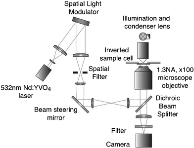
The experimental setup used for creating the biological architectures was based around a ×100 1.3NA oil immersion objective (PlanNeoFluor Zeiss) with a trapping laser and a spatial light modulator, as illustrated in Fig. 1. Details of the exact experimental conditions for trapping different structures, and of the algorithms used for the creation of the desired trapping patterns to create different architectures are provided in the text, as appropriate (in general a simple algorithm combining diffraction gratings and Fresnel lenses was used to form the hologram for display on SLM). | ||
| Fig. 1 The experimental configuration of the holographic optical tweezers for trapping and positioning the particles/cells forming the 3D structure. | ||
Imaging of structures
The structures were imaged, ex-situ (i.e. removed from the tweezers) using either confocal (based around a Nikon eclipse E600FN microscope with a Nikon CFI60, Plan Fluor ×100, 1.3NA series oil immersion objective and a MRC-1024ES, housing the PMTs and scanning optics) or multiphoton imaging. The multi-photon imaging was performed using a fs pulsed Coherent Mira 900 Ti-sapphire laser (tuneable between 700 and 900 nm), pumped by a 5W Coherent Verdi laser. All multi-photon imaging was performed at 780 nm using a ×100 1.35NA oil immersion objective lens and data was collected using LaserSharp 2000, Version 5.2 software. Images were analyzed using PicViewer v2.4.Permanent trapping of fluorescent microparticles
Following a similar approach to ref. 12, the basic configuration in Fig. 1 was used with a variable power (max. 1.5 W), 532 nm Nd∶YAG laser (“Excel”, Photonics Solutions) and an SLM (LCR-2500 HoloEye). The Holoeye SLM is an electronically addressed nematic liquid crystal with 1024 × 768 pixels, a refresh rate of 72 Hz and a diffraction efficiency in excess of 40%. 5 µl of 1.8 µm diameter polystyrene fluorescent beads (Sigma, product number L-0905, which absorb at 470 nm and are fluorescent at 505 nm), were suspended in a gelatin solution consisting of 0.4 g gelatin mixed with 12 ml of water. The spheres were trapped in the desired 2D or 3D patterns. Once trapped, the spheres were left for 2–3 h with the laser switched on until the gelatin set. Typically, 75–100 mW of power was delivered in the trapping plane to maintain the configurations. Once the gelatin had set around the micro-structure, the laser was switched off and the structure was protected from evaporation by adhering a cover slip onto the top of the sample.Permanent trapping of E. coli
For all experiments involving the bacteria, the 532 nm laser was replaced with one operating at 1064 nm with a maximum power of 3 W (Quantum Venus). The infrared laser was used to trap the bacteria as it does not cause as much thermal damage to biological objects as does a shorter wavelength laser.13 The change in operating wavelength also required replacement of the SLM with a unit optimized for IR operation (X8267 SLM, Hammamatsu Photonics). As an alternative to the simple grating and lens algorithm, the hologram to produce the body centred rectangular structure was designed using a modified Gerchberg–Saxton algorithm.9A stock solution of HB101 E. coli was prepared as previously described. 0.3 g gelatin was added to 15 ml of an appropriate buffer before mixing 10 µl of the stock E. coli with 400 µl of the gelatin mixture. 200 µl of the resulting mixture was placed into the sample container of the optical tweezers. Bacteria were trapped in a variety of different geometries. In the examples shown bacteria are trapped and subsequently set at the centre and corners of a cuboid. During the initial optical manipulation, typically 10 min, the optical power in the traps was of order 200 mW. During the setting procedure, typically one hour, this was reduced to approximately 100 mW.
Permanent setting of labelled E. coli
A stock solution of HB101 E. coli was prepared as previously described. 10 µl of the primary antibody (10 µg ml−1) was added to the bacteria and the sample left for 10 min. Excess liquid was removed by centrifugation and washing in buffer. The resulting pellet was finally resuspended in 1 ml of PBS. 10 µl of the secondary antibody was then added and left for 10 min. The process of bacteria isolation by centrifugation was repeated.This pellet of labelled E. coli was then resuspended in 10 µl of PBS, and 3 µl of the resulting tagged E. coli stock solution was added to 400 µl of 0.3 g gelatin and 15 ml of water solution. This sample was placed in the optical tweezers. Again, a modified Gerchberg–Saxton algorithm was used in order to design the hologram of the desired 2D structure which in this case was the “No. 5” shape found on a dice. The optical power levels and durations were similar to those employed for the trapping of unlabelled bacteria. Once the gelatin had set, the sample was sealed with a cover slip and again imaged using a confocal microscope.
Bacterial viability
50 µl of MC4100 E. coli stock was added to 30 ml of LB nutrient broth (Merck, Germany) and incubated in a glass beaker at 37 °C for 12 h. 1 ml of this cultured E. coli sample was added to 30 ml of fresh LB nutrient broth for experimental use.0.6 g of gelatin was added to 10 ml RO water at 80 °C and kept warm until the gelatin dissolved. 75 µl of the 0.6 g gelatin solution was mixed with 75 µl of the E. coli and nutrient broth solution in a 1.5 ml aliquot, resulting in a 3% wt/v mixture. 1 ml of the resulting gelatin and E. coli mixture was added to 1.5 µl propidium iodide (Molecular Probes) and incubated in darkness for 10 min. Sample cells consisted of 120 µm deep spacers (Molecular Probes) on glass microscope slides. 8.5 µl of gelatin, E. coli, nutrient broth and propidium iodide mixture was placed onto the glass slide in the spacer and a cover slip sealed the chamber. The stained E. coli samples were imaged using a confocal microscope. The 488 nm line of an Ar+ laser was used to excite the propidium iodide dye used to stain the E. coli.
Results and discussion
Permanent trapping of beads
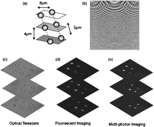
A number of experiments were performed using beads as model systems to optimize the experimental procedure both in terms of trapping and subsequent imaging. For example, Fig. 2 shows 6 fluorescently labelled spheres, trapped in pairs in three different planes. | ||
| Fig. 2 Permanently set 3D structure of fluorescent spheres. A schematic of the structure (a), the hologram used to create the traps (b), and images taken in optical tweezers (c), and then removed from the tweezers and imaged within a confocal (d) and multi-photon (e) microscope. | ||
Permanent trapping of E. coli
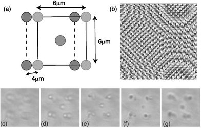
In Fig. 3 we show E. coli configured into a body centred cubic structure. The E. coli was set at the corners of a body centred lattice with dimension 6 µm × 6 µm × 4 µm. | ||
| Fig. 3 Permanently set 3D structures of E. coli. A schematic of the structure (a), the hologram used to create the traps (b) and images of the structure at various depths taken on the optical tweezers system (c)–(g). The two squares creating the structure are 6 µm across separated axially by 4 µm. | ||
Fluorescently tagged E. coli were also used to produce a 2D structure. Once set, the structure was sealed and the sample was removed from the tweezers and imaged as described earlier, Fig. 4.
 | ||
| Fig. 4 Permanently set body-centred structure of tagged E. coli. A schematic of the structure (a), the hologram used to create the traps (b), an image of the structures taken in the optical tweezers (c) and a fluorescent image recorded in the confocal microscope (d). | ||
Viability of E. coli
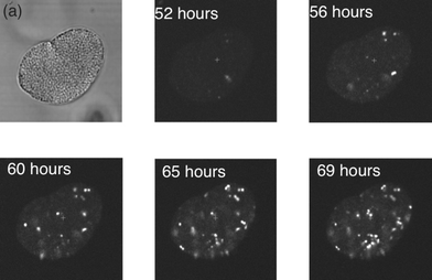
E. coli taken from the exponential growth phase were mixed with nutrient broth and gelatin to produce a 3% wt/v sample which was imaged at various times. Propidium iodide stains the bacteria and causes it to fluoresce when the cell membrane is damaged, making it ideal for identifying damaged or decayed E. coli cells within a population. Viable E. coli that are intact do not take up any of the stain, intracellularly.14 Although these latter experiments were performed in the absence of the trapping beams, the use of infra-red traps for short periods is known to leave the viability of many E. coli undamaged.13Accumulative scans of the bacteria were taken in order to detect whether an intracellular propidium iodide fluorescence signal was present. Fig. 5 shows an example of a series of fluorescence images, showing an E. coli cluster in 3% wt/v gelatin and nutrient broth mixture. The fluorescent signal started to appear after 50 h, as shown in the frames taken between 52 and 69 h after the culture was established. It can be seen that as the bacterial membrane becomes compromised, there is an increase in the amount of fluorescent signal detected. Despite being set in gelatin for 72 h with nutrient broth, the majority of E. coli could be recovered from the structure and sub-cultured overnight on an agar plate incubated at 37 °C.
 | ||
| Fig. 5 Bacterial viability in gelatin. A cluster of bacteria imaged 52 h after being selected from the nutrient broth, and then subsequently at ca. 4 h intervals. Each image involved using an accumulation scan over 20 frames. | ||
In conclusion, we show for the first time, that 2D and 3D structures of cells can be readily created using holographic optical tweezers and set within a gelatin matrix. These structures can be sealed and successfully moved to different locations, and re-imaged using confocal and multi-photon microscopy. We demonstrate the flexibility of this approach by arranging isolated cells in a variety of complex patterns, with respect to each other.
The importance of the methods described in this paper may, in future, be illustrated by the ability to organize cells spatially into well-defined 3D arrays to help in tissue replacement therapies. For example, we already know that hepatocytes cultured as a monolayer quickly lose specific functions, whilst those same cells in a quasi 3D collagen matrix (mimicking their natural structure) retain their normal functions for weeks in culture.15 Using holographic optical tweezers may therefore have important consequences in understanding the role of position, proximity and number of neighbouring cells, not only in cell culture, but also in cell differentiation. The ability to form such viable 3D structures will open a wide range of future applications, and we can confidently predict the possibility for organizing stem cells into novel or complex geometries, allowing for the study of the collective behaviour of many-body structures will yield exciting results over the coming decade.
References
- A. Ashkin, J. M. Dziedzic, J. E. Bjorkman and S. Chu, Observation of a single-beam gradient force optical trap for dielectric particles, Opt. Lett., 1986, 11, 288–290 CAS.
- J. E. Molloy and M. J. Padgett, Lights, action: optical tweezers, Contemp. Phys., 2002, 43, 241 CrossRef CAS.
- S. M. Block, D. F. Blair and H. C. Berg, Compliance of bacterial flagella measured with optical tweezers, Nature, 1989, 338, 514 CrossRef CAS.
- H. He, M. E. J. Friese, N. R. Heckenberg and H. Rubenstien-Dunlop, Direct observation of transfer of angular momentum to absorptive particles from a laser-beam with a phase singularity, Phys. Rev. Lett., 1995, 75, 826 CrossRef CAS.
- A. T. O'Neil, I. MacVicar, L. Allen and M. J. Padgett, Intrinsic and extrinsic nature of the orbital angular momentum of a light beam, Phys. Rev. Lett., 2002, 88, 03601.
- D. G. Grier, A revolution in optical manipulation, Nature, 2003, 424, 810–816 CrossRef CAS.
- K. C. Neuman and S. M. Block, Optical trapping, Rev. Sci. Instrum., 2004, 75, 2787–2809 CrossRef CAS.
- M. Reicherter, T. Haist, E. U. Wagemann and H. J. Tiziani, Optical particle trapping with computer generated holograms written on a liquid crystal display, Opt. Lett., 1999, 24, 608–610.
- J. E. Curtis, B. A. Koss and D. G. Grier, Dynamic holographic optical tweezers, Opt. Commun., 2002, 207, 169–175 CrossRef CAS.
- G. Sinclair, P. Jordan, J. Leach, M. J. Padgett and J. Cooper, Defining the trapping limits of holographical optical tweezers, J. Mod. Opt., 2004, 51, 409–414 CrossRef.
- G. Sinclair, P. Jordan, J. Courtial, M. Padgett, J. Cooper and Z. J. Laczik, Assembly of 3-dimensional structures using programmable holographic optical tweezers, Opt. Express, 2004, 12, 5475 Search PubMed.
- P. Jordan, H. Clare, L. Flendrig, J. Leach, J. Cooper and M. Padgett, Permanent 3D microstructures in a polymeric host created using holographic optical tweezers, J. Mod. Opt., 2004, 51, 627–632 CrossRef CAS.
- A. Ashkin, J. M. Dziedzic and T. Yamane, Optical trapping and manipulation of single cells using infrared laser beams, Nature, 1987, 330, 769–771 CrossRef CAS.
- M. Ericsson, D. Hanstorp, P. Hagberg, J. Enger and T. Nyström, Sorting out bacterial viability with optical tweezers, J. Bacteriol., 2000, 182, 5551–5555 CrossRef CAS.
- J. C. Y. Dunn, M. L. Yarmush, H. G. Koebe and R. G. Tompkins, Hepatocyte function and extracellular-matrix geometry—long-term culture in a sandwich configuration, FASEB J., 1989, 3, 174 Search PubMed.
| This journal is © The Royal Society of Chemistry 2005 |
