Development of a microfluidic biosensor module for pathogen detection
Natalya V.
Zaytseva
a,
Vasiliy N.
Goral
b,
Richard A.
Montagna
b and
Antje J.
Baeumner
*a
aDepartment of Biological and Environmental Engineering, Cornell University, Ithaca, NY 14853, USA. E-mail: ajb23@cornell.edu; Fax: +1-607-255-4080; Tel: +1-607-255-5433
bInnovative Biotechnologies International, Inc., Grand Island, NY 14072, USA
First published on 6th July 2005
Abstract
The development of a microfluidic biosensor module with fluorescence detection for the identification of pathogenic organisms and viruses is presented in this article. The microfluidic biosensor consists of a network of microchannels fabricated in polydimethylsiloxane (PDMS) substrate. The microchannels are sealed with a glass substrate and packed in a Plexiglas housing to provide connection to the macro-world and ensure leakage-free flow operation. Reversible sealing permits easy disassembly for cleaning and replacing the microfluidic channels. The fluidic flow is generated by an applied positive pressure gradient, and the module can be operated under continuous solution flow of up to 80 µL min−1. The biosensor recognition principle is based on DNA/RNA hybridization and liposome signal amplification. Superparamagnetic beads are incorporated into the system as a mobile solid support and are an essential part of the analysis scheme. In this study, the design, fabrication and the optimization of concentrations and amounts of the different biosensor components are carried out. The total time required for an assay is only 15 min including sample incubation time. The biosensor module is designed so that it can be easily integrated with a micro total analysis system, which will combine sample preparation and detection steps onto a single chip.
Introduction
Microfluidic devices integrating sample handling, reagent mixing, separation and detection processes are of considerable interest. Since the early 1990s, when the modern concept of the micro total analysis system (μTAS, or lab-on-a-chip) was proposed by Manz et al.,1 considerable effort was made towards the development of highly miniaturized analytical systems. Miniaturization revealed many potential benefits including low consumption of costly reagents and power, minimized handling of hazardous materials, short reaction times, portability and versatility in design, and capability for parallel operation. A comprehensive overview of important accomplishments in theoretical understanding, technology and applications in the field of μTAS and microfluidics is given by Reyes and colleagues.2,3 Advances in micro- and nanofabrication techniques have promoted a rapid evolution from simple systems to prototypes of the lab-on-a-chip.4–9 Showing proof of principle, many examples of bioassays and biological procedures have been miniaturized into a chip format including polymerase chain reaction (PCR),10,11 DNA analysis and sequencing,12,13 electrophoresis,14,15 immunoassays,16–18 and intra- and inter-cellular analysis.19,20 One of the main challenges in microfluidics is certainly the integration of multiple procedures and functional components into a single chip to perform the total analysis of the whole sample.In our laboratory a bioanalytical microsystem is being developed for rapid and reliable identification of pathogenic organisms and viruses. The bioanalytical microsystem is realized on a microfluidic platform and will integrate sample preparation and detection steps onto one chip, eliminating the need of manual user input and macro apparatus. Pathogenic organisms such as Bacillus anthracis,21,22Cryptosporidium parvum,23Escherichia coli24,25 and Dengue virus26,27 are identified via their specific messenger or genomic RNA. Well-understood technology of lateral flow RNA assay previously developed in our laboratory is adapted to the microfluidic system. The design for this system is modular, i.e. the analytical operations required for the analysis, i.e. cell lysis,28 RNA purification, nucleic acid sequence-based amplification (NASBA) and RNA detection, are performed in separate modules. The modules combined together will compose the microsystem. In this paper we present the development of the microfluidic biosensor module with fluorescent detection for the identification of Dengue virus as a model analyte. The module is designed to be easily integrated with future modules fabricated with the same technology. A network of microchannels comprising the microbiosensor is modeled using computer aided design software, nanofabricated in a silicon wafer by photolithography and etching techniques and molded into a PDMS elastomer by replica molding.
The principle of the biosensor is based on the DNA/RNA hybridization system and liposome signal amplification (Fig. 1).
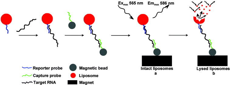 | ||
| Fig. 1 The principle scheme of the biosensor based on DNA/RNA hybridization, magnetic bead complex formation, and fluorescence detection of RNA-specific complexes via intact (a) and lysed (b) liposomes. | ||
Two sets of DNA probes hybridize specifically with the viral target RNA. A generic probe is designed to bind to each of the four Dengue virus serotypes, and four specific probes are designed to bind to the specific serotype only.29 The generic probe (reporter probe) is coupled to liposomes that encapsulate a fluorescent dye, sulforhodamine B (SRB). The specific probes (capture probes) are immobilized on the surface of superparamagnetic microbeads via biotin–streptavidin interaction. Target RNA is amplified using the isothermal NASBA reaction.30 Liposomes with reporter probes and beads with capture probes are incubated with amplified target prior to introduction of the mixture into the microchannel where the sandwich complexes subsequently are captured on the magnet and detected by means of fluorescence microscopy.
We demonstrate in this paper a simple way of manipulating magnetic beads within the microchannel by using an externally positioned magnet. Paramagnetic beads have been extensively used to facilitate the downscaling of conventional analysis techniques to the micrometer scale and have been shown to be very suitable for immunoassays,31 mRNA isolation,32 or DNA hybridization.33 The bead-based materials are ideal for reagent delivery and provide a large reactive surface area.34
In this study, the detection of specific nucleic acid sequences is performed in the microfluidic biosensor module to demonstrate the advantages of using magnetic beads, small-volume samples and fluorescent liposomes as a marker. The liposomes carry a large number of fluorophore molecules and provide an excellent signal-to-noise ratio. In addition, the liposomes can be disrupted easily by a surfactant allowing rapid release of fluorescent molecules from the liposome's aqueous core resulting in a significant increase of the fluorescence signal due to elimination of fluorophore self-quenching.
Experimental
Materials and reagents
All general chemicals and buffer reagents were obtained from Sigma Company, St. Louis, MO. Organic solvents were purchased from Aldrich Chemical Company, Milwaukee, WI. Membranes were obtained from Pall/Gelman Company, Port Washington, NY. Lipids were purchased from Avanti Polar Lipids, Alabaster, AL. Sulforhodamine B was acquired from Molecular Probes Company, Eugene, OR. Octyl-β-D-glucopyranoside (OG) was purchased from Alexis Corporation, Lausen, Switzerland. All oligonucleotides including cholesterol-tagged reporter probe were purchased from Qiagen, Valencia, CA. Silicone elastomer kit Sylgard®184 containing polydimethyl siloxane (PDMS) prepolymer and catalyst was obtained from Dow Corning Corp., Midland, MI. Superparamagnetic beads (Dynabeads MyOne Streptavidin) were purchased from Dynal Biotech Inc. (Lake Success, NY, USA). Stainless steel and Tygon® tubing was supplied by Small Parts Inc., Miami Lakes, FL. Syringes were purchased from Hamilton Company, Reno, ND. The Cornell Nanofabrication Facility (CNF) provided clean room facilities, chemicals and equipment for silicon template fabrication. The Plexiglas® housing was constructed in the machine shop located at the School of Chemical and Biomolecular Engineering, Cornell University.Biosensor module fabrication
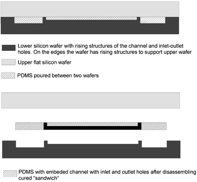 | ||
| Fig. 2 Fabrication of microchannels using the replica molding technique. In this method a silicon wafer with a positive surface relief is used as a mold and a second silicon wafer with a flat surface is used as a lid to control flatness and thickness of the PDMS film. | ||
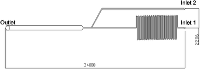 | ||
| Fig. 3 Typical channel layout with dimensions in µm. The enlarged area adjacent to the outlet hole (500 µm in width) is the detection zone; two channels, 100 µm wide, with inlet 1 and 2 are used for the introduction of materials. | ||
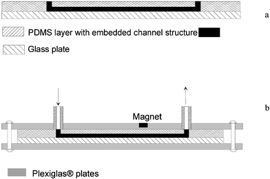 | ||
| Fig. 4 Assembly of the microfluidic device. (a) The PDMS film with microchannels is laid onto a glass plate in order to close the microchannel structure. (b) The PDMS-glass plate structure is held together by applying a slight pressure using a housing consisted of two Plexiglas® plates and 8 screws. | ||
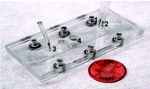 | ||
| Fig. 5 Assembled microfluidic device used as a biosensor module. The device consists of PDMS microchannels sealed with a glass substrate and is packed in Plexiglas® to provide a connection to the macro-world (1, 2—inlet ports, 3—outlet port, 4—magnet location). | ||
DNA oligonucleotides
Amplified sequences of Dengue virus RNA27 were used for all hybridization sandwich assays. DNA reporter and capture probes had been designed earlier29 and their sequences were previously described.26 A cholesterol-tagged (via the 5′ end) reporter probe was incorporated into liposomes during the liposome synthesis.37 The serotype-specific capture probes were modified with a biotin at the 5′ end and immobilized on the streptavidin coated paramagnetic beads. The sequence layout is shown in ref. 27.Liposomes
The liposomes were prepared using a modified version38 of the reversed phase evaporation method described by Siebert and colleagues.39Immobilization of oligonucleotides on the bead surface
Conjugation of biotinylated capture probes to streptavidin coated superparamagnetic beads was carried out according to the manufacturer protocol. Briefly, 20 µL of bead stock (10 mg mL−1) were washed two times in 2× concentrated Binding and Washing (B&W) buffer (10 mM Tris-HCl, 1 mM EDTA, 2 M NaCl, pH 7.5) and resuspended in 18 µL of 1× concentrated B&W buffer. 2 µL of DNA capture probe (300 nmol mL−1) were added to the beads and the resultant mixture was placed on a rotator for 15 min at RT to allow conjugation. After conjugation, the beads were washed 3 times with 1× B&W buffer and resuspended in the same buffer to a final volume of 20 µL. The beads with immobilized oligonucleotides could be stored at 4 °C for several months.Biosensor module operation and assay protocol
Fluid flow through the channel network was established by applying a positive pressure at the inlet using a syringe pump (KD Scientific Inc., Holliston, MA) and opening the outlet to atmospheric pressure. The connection between the top of the steel tubing and 500 µL Hamilton gastight syringes on the pump was made via Tygon® tubing with an inner diameter of 0.5 mm. All channels were prefilled with running buffer (10% formamide, 3 × SSC, 0.2 M sucrose, 0.2% Ficoll type 400, 0.01% Triton X-100) at a slow flow rate of 1 µL min−1 to prevent the formation of bubbles. In a microcentrifuge tube, 1 µL of a hybridization solution (master mix) in optimal composition (60% formamide, 6 × SSC, 0.15 M sucrose, 0.8% Ficoll type 400, 0.01% Triton X-100), 1 µL of target sequence (RNA sample) or water (for a negative control), 1 µL of bead suspension containing 1 µg of beads, and 1 µL of liposomes were incubated for 10 min at room temperature in a shaker. Following the incubation, the mixture was loaded into the microfluidic channel through inlet 1 at flow rate of 14 µL min−1. The liposome–target sequence–bead complexes formed were captured by the magnet in the detection zone. After all of the beads with the specific complexes were collected on the magnet and unbound liposomes were washed away with running buffer, OG solution at the concentration of 30 mM was injected through inlet 2 in order to lyse the liposomes and release the sulforhodamine B dye molecules into the microchannel. The analytical procedures required for single biosensor assay are summarized in Table 1.| Procedure | Time and flow rate |
|---|---|
| Collecting beads on the magnet and washing unbound liposomes | 2 min, 14 µL min−1 |
| Fluorescence detection of intact liposomes | 30 s |
| Liposome lysis and fluorescence detection | 2 min, 0.8 µL min−1 |
| Washing the channels to repeat the analysis (the magnet is removed from the groove) | 1 min, 14 µL min−1 |
Fluorescence of intact and lysed liposomes was visualized using a Leica DMLB microscope (Leica Microsystems, Wetzlar, Germany) with a set-up as follows: a 10×/0.25 NA long working distance objective, the appropriate filter set (540/25 nm band pass exciter; 620/60 nm band pass emitter), and 100 W mercury illumination source. The images of beads in the detection zone were obtained with a digital CoolSnap CCD camera (Photometrics, Tucson, AZ) coupled to image acquisition software (Roper Scientific Inc., Tuscon, AZ). The fluorescence signal was quantified via pixel value analysis of the acquired image using Image ProExpress software (Media Cybernetics, Silver Spring, MD). The average pixel value of the detection zone was considered as fluorescence intensity of a given sample.
Results and discussion
Device fabrication
The biosensor module consists of microfluidic channels fabricated in PDMS elastomer using the replica-molding technique. The elastomer was chosen as material since it has numerous advantages over silicon and glass initially used for microfabrication. The elasticity of PDMS allows for easy, nondestructive release and replication from the reusable silicon master. The PDMS is optically transparent down to 300 nm and does not show any autofluorescence that is advantageous for our detection method, fluorescence microscopy. The PDMS is inexpensive, inert and biocompatible. The procedure of producing PDMS replicas can be carried out under normal laboratory conditions without an expensive clean room. Most importantly, the PDMS can be bonded to other flat surfaces under ambient conditions (unlike silicon and glass, for which bonding requires high temperature or adhesives).40In our microfluidic device the PDMS microchannels were sealed to the glass substrate reversibly by conformal contact. This meant that the seal between upper and lower substrate was not permanent and the PDMS film could be easily separated to allow any blockages to be removed. After cleaning, the PDMS microchannels, if desired, can be reused. Normally, two pieces of PDMS or PDMS and glass are sealed using plasma treatment; however, this procedure can damage surfaces onto which biological materials have been immobilized or delicate nanofabricated structures were made. Thus, plasma treatment is often a poor choice to seal a channel structure. Therefore, pressure-closed housing was designed to obtain a microchannel structure that can be used in a variety of different applications. The plastic housing and the flexibility of the PDMS, which can conform to minor imperfections of flat surfaces, provided a watertight sealing at the glass-PDMS interface.
The microfluidic system previously developed in our laboratory35 in which a simple well was used for introduction of materials and fluid flow was driven by vacuum, did not provide precise enough sample handling, in terms of volume and flow rate. Therefore, it was important to automate the flow of microliters of sample fluid across the microfluidic device. For this purpose, stainless steel tubing was glued into the access holes of one of the Plexiglas plates. These integrated inter-connectors provided a link between the micro-components of the device and external fluidics (a syringe and plastic tubing). Two strategies significantly reduced the dead volume and minimized stagnated flow during the continuous operations of fluid flow inside the microfluidic device. First, the inter-connectors were made coplanar with the plastic surface. The holes in the Plexiglas were drilled so that the metal tubing could fit perfectly and come in close contact with the PDMS surface (Fig. 4b). Second, the inlet and outlet holes in the PDMS film were made vertically through the entire thickness of the PDMS and had a diameter not larger than the width of the microchannel.
In the pressure driven flow, the flow rate Q
(m3 s−1) within a microchannel is defined by
where w is the width of channel, h is the height of channel, L is the length of channel, and μ is the viscosity of the working fluid.41 The resistance of a rectangular microchannel with a high aspect ratio (w ≪ h or w ≫ h) can be calculated by
Because of the relation ΔP ∼ 1/wh3 higher pressure drops are needed to drive fluid flow in smaller microchannels. To avoid high pressure drops and therefore prevent possible leakage in the microfluidic device, the cross-sectional area of 100 × 50 µm2 was adopted for general layout of microfluidic channels. For the channel height below 50 µm, a pressure drop in 100 × 30 µm2 and 100 × 10 µm2 channels increases by factors of ∼4 and ∼92, correspondingly.
To conclude that the prepared assembly is suitable for the operation under the conditions of continuous solution flow, leakage from the microchannels was visually examined. The injection of buffer solution into the microchannels was carried out by syringe pumps varying the flow velocities from 0.5 to 100 µL min−1. The microfluidic module showed no solution leakage up to 80 µL min−1. However, this velocity was too high for the efficient capture of magnetic beads used in the hybridization assay and, as discussed further, the device was operated at flow rate of 14 µL min−1.
Magnetic beads capture in the microfluidic device
An externally positioned permanent magnet has been used to manipulate paramagnetic particles within the microchannel. The distance between the magnet and the capture zone of the microfluidic channel was precisely controlled by two parameters: the depth of the groove in which the magnet was placed and the thickness of the PDMS film. These parameters have a great influence on the ability to capture beads efficiently at increasing flow rates. For a circular permanent magnet with a radius R and a length L, the magnetic field along the axis of the magnet at a distance D from its surface can be calculated by the following formula (where Br is the residual induction of the material)Therefore, the closer the magnet is positioned to the microchannel, the stronger the magnetic field applied to capture the magnetic beads, and as a result, the higher the flow rates used during the analysis.
An important feature of the microchannel design was that the capture zone was widened and had a cross-sectional area 5 times larger than the microchannels. This design prevented bead bed extension across the entire channel and diminished higher shear rates. Otherwise, the forces from the backpressure of the fully packed bed and a high linear velocity would overpower the magnetic field gradient, and the bead bed would be flushed away.
About 100% efficiency of bead capture was achieved at a loading flow rate of 14 µL min−1 (linear velocity of ∼9 mm s−1). The densely packed bead region (∼1 mm in length) was reproducibly formed (Fig. 6) and resisted deformations throughout the experiments. Once the experiment was finished, the magnetic particles could be quickly flushed away by removing the magnet from the groove.
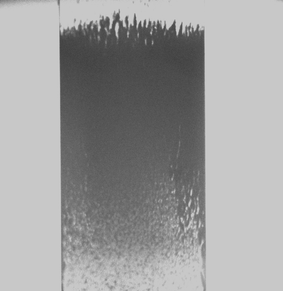 | ||
| Fig. 6 Brightfield image of beads localized by a magnet in the 500 µm detection zone of the microchannel. | ||
Hybridization assays
Two sets of magnetic beads, Dynabeads M-270 and Dynabeads My One Streptavidin, were evaluated in the hybridization assays. The beads are uniform in size, superparamagnetic, and polystyrene-coated with a monolayer of streptavidin covalently attached to the bead surface. The diameters of M-270 and My One beads are 2.8 µm and 1 µm, correspondingly. Thus, beads with the smaller diameter have a higher binding capacity, ∼3000 pmol of biotin per mg versus ∼700 pmol of biotin per mg for M-270. The Dynabeads My One have a lower sedimentation rate that prevents fast bead settlement during pumping and ensures signal reproducibility. In addition, we experimentally determined that, in contrast to the M-270 beads, the Dynabeads My One demonstrate less autofluorescence and a lower background signal. Therefore, the Dynabeads My One were chosen for all further experiments.The biorecognition element in the microfluidic biosensor module consisted of two DNA oligonucleotides, capture and reporter probes that were complementary to two separate regions of the target RNA. Biotinylated capture probes were bound via streptavidin–biotin conjugation to the surface of the paramagnetic beads while reporter probes were attached to the surface of the liposomes during the liposome synthesis. In the presence of RNA molecules amplified by NASBA both probes hybridize to the target RNA forming liposome–target–bead complexes. The hybridization reactions were carried out off-chip for this work, although we demonstrated that these reactions can be performed on-chip as well.35 The liposome–target–bead complexes were localized in the capture/detection zone of the microchannel by a permanent magnet after the hybridization mixture was loaded into the microfluidic device. The amount of beads and liposomes was optimized to give the highest fluorescence signal at 10× magnification of the detection zone. The specific complexes were detected by measuring red fluorescence of SRB molecules encapsulated in the liposomes (Fig. 1a).
Since the SRB molecules encapsulated in the liposomes at high concentrations undergo self-quenching, the fluorescence signal from the captured intact liposomes was relatively low (Fig. 7b). The signal can be dramatically increased upon liposome lysis with a nonionic surfactant, n-Octyl-β-D-glucopyranoside (OG). At the surfactant concentrations lower than the critical micellar concentration (CMC) the detergent molecules intercalate into the lipid bilayer causing its perturbation and allowing leakage of the dye entrapped into the liposomes. At CMC or higher a complete breakage of liposomes into micelles occurs leading to a rapid dilution of SRB molecules and dequenching of fluorescence signal42 (Fig. 1b). In Fig. 7c a significant increase in fluorescence was observed after the liposomes were lysed with 30 mM OG solution. From Fig. 7b and 7c it can be seen that the lysed liposomes yielded a signal approximately 6 times higher than the intact one. At the exposure time of 1 s the high fluorescence intensity for lysed liposomes caused the overexposure of the CCD sensor yielding an average intensity value of 253 that was very close to the maximum pixel value for the 8-bit-per-channel CCD camera (i.e. 255). In order to avoid the overexposure and maximize the difference in fluorescence between intact and lysed liposomes, shorter exposure time along with decreased intensity from the excitation light source should be used. In addition, for the detection of lysed liposomes, an integration over the period of time during which lysed liposomes pass the detection zone will result in a significantly higher signal that is partly lost when only taking a single frame analysis as in Fig. 7c.
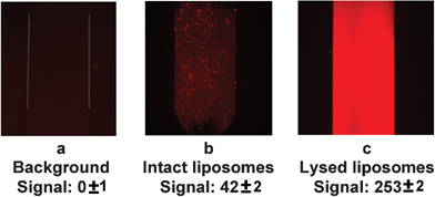 | ||
| Fig. 7 Fluorescence images of the capture zone with immobilized superparamagnetic beads: (a) no RNA present in a sample (background), (b) intact liposomes bound in specific complexes with the target RNA, (c) fluorescence dequenching of liposomes upon addition of the surfactant. All analyses were done in triplicate and representative images are shown here. | ||
Due to the fact that a single liposome can entrap approximately 105 fluorophore molecules43 ensuring large signal amplification for each binding event, the developed microfluidic biosensor based on the fluorescence measurements of lysed liposomes provide very sensitive, quantitative and fast detection of bacterial pathogens and viruses.44 However, a simpler design can be achieved using non-lysed liposomes since no second channel and switching of flow rates are required when analyzing intact liposomes. For this purpose, liposomes can be synthesized with a decreased concentration of SRB leading to less quenching and thus a higher signal for non-lysed liposomes.
Conclusions
We have developed a microfluidic biosensor module, based on fluorescent detection, which can be used for the rapid identification of pathogenic organisms and viruses via their messenger, ribosomal or genomic RNA. The approach applied for the construction of the microfluidic module provided a precise sample handling in terms of volume and flow rates, minimal dead volume at the inlet and outlet holes (no sample losses during the analysis and ∼100% waste disposal), and the ability for quick interchange of channels with different geometries and dimensions. The use of a permanent magnet located on the outside of the device allowed an easy manipulation (collection, washing, removing) of paramagnetic particles inside the microchannel. We demonstrated the operational efficiency of this approach in the detection of Dengue virus RNA.Acknowledgements
The authors acknowledge financial support for this project from Innovative Biotechnologies International, Inc., from the National Institute of Allergy & Infectious Diseases (NIAID), Bethesda, MD, from the New York State CAT, Biotechnology Program at Cornell University, and from the Cooperative State Research, Education and Extension Services (NYC-123314). We thank Sutee Yoksan from Mahidol University, Thailand and Shuenn-Jue Wu from Naval Medical Research Center, USA for providing us with Dengue virus samples that were used in this publication. This work was performed in part at the Cornell Nanofabrication Facility (a member of the National Nanofabrication Users Network), which is supported by the National Science Foundation under Grant ECS 03-35765, its users, Cornell University and Industrial Affiliates.References
- A. Manz, N. Graber and H. M. Wildmer, Miniaturized total chemical analysis systems: a novel concept for chemical sensing, Sens. Actuators B, 1990, 1, 244–248 CrossRef.
- D. R. Reyes, D. Iossifidis, P.-A. Auroux and A. Manz, Micro total analysis systems. 1. Introduction, Theory, and Technology, Anal. Chem., 2002, 74, 2623–2636 CrossRef CAS.
- D. R. Reyes, D. Iossifidis, P.-A. Auroux and A. Manz, Micro total analysis systems. 2. Analytical Standard Operations and Applications, Anal. Chem., 2002, 74, 2637–2652 CrossRef CAS.
- M. A. Burns, B. N. Johnson, S. N. Brahmasandra, K. Handique, J. R. Webster, M. Krishnan, T. S. Sammarco, P. M. Man, D. Jones, D. Heldsinger, C. H. Mastrangelo and D. T. Burke, An integrated nanoliter DNA analysis device, Science, 1998, 282(5388), 484–487 CrossRef CAS.
- R. H. Liu, J. N. Yang, R. Lenigk, J. Bonanno and P. Grodzinski, Self-contained, fully integrated biochip for sample preparation, polymerase chain reaction amplification, and DNA microarray detection, Anal. Chem., 2004, 76(7), 1824–1831 CrossRef CAS.
- D. Erickson and D. Li, Integrated microfluidic devices, Anal. Chim. Acta, 2004, 507, 11–26 CrossRef CAS.
- E. T. Lagally and R. A. Mathies, Integrated genetic analysis microsystems, J. Phys. D: Appl. Phys., 2004, 37, R245–R261 CrossRef CAS.
- P.-A. Auroux, Y. Koc, A. deMello, A. Manz and P. J. R. Day, Miniaturised nucleic acid analysis, Lab Chip, 2004, 4(6), 534–546 RSC.
- E. T. Lagally, J. R. Scherer, R. G. Blazej, N. M. Toriello, B. A. Diep, M. Ramchandani, G. F. Sensabaugh, L. W. Riley and R. A. Mathies, Integrated portable genetic analysis microsystem for pathogen/infectious disease detection, Anal. Chem., 2004, 76(11), 3162–3170 CrossRef CAS.
- M. Hashimoto, P. C. Chen, M. W. Mitchell, D. E. Nikitopoulos, S. A. Soper and M.C. Murphy, Rapid PCR in a continuous flow device, Lab Chip, 2004, 4(6), 638–645 RSC.
- E. T. Lagally, C. A. Emrich and R. A. Mathies, Fully integrated PCR-capillary electrophoresis microsystem for DNA analysis, Lab Chip, 2001, 1(2), 102–107 RSC.
- C. F. Chou, O. Bakajin, S. W. P. Turner, T. A. J. Duke, S. S. Chan, E. C. Cox, H. G. Craighead and R. H. Austin, Sorting by diffusion: An asymmetric obstacle course for continuous molecular separation, Proc. Natl. Acad. Sci. USA, 1999, 96(24), 13762–13765 CrossRef CAS.
- N. Goedecke, B. McKenna, S. El-Difrawy, L. Carey, P. Matsudaira and D. Ehrlich, A high-performance multilane microdevice system designed for the DNA forensics laboratory, Electrophoresis, 2004, 25(10–11), 1678–1686 CrossRef CAS.
- D. C. Duffy, J. C. McDonald, O. J. A. Schueller and G. M. Whitesides, Rapid prototyping of microfluidic systems in poly(dimethylsiloxane), Anal. Chem., 1998, 70(23), 4974–4984 CrossRef CAS.
- P. S. Doyle, J. Bibette, A. Bancaud and J. L. Viovy, Self-assembled magnetic matrices for DNA separation chips, Science, 2002, 295(5563), 2237–2237 CrossRef CAS.
- N. Chiem and D. J. Harrison, Microchip-based capillary electrophoresis for immunoassays: Analysis of monoclonal antibodies and theophylline, Anal. Chem., 1997, 69(3), 373–378 CrossRef CAS.
- L. C. Campbell, M. J. Wilkinson, A. Manz, P. Camilleri and C. J. Humphreys, Electrophoretic manipulation of single DNA molecules in nanofabricated capillaries, Lab Chip, 2004, 4(3), 225–229 RSC.
- J. Moorthy, G. A. Mensing, D. Kim, S. Mohanty, D. T. Eddington, W. H. Tepp, E. A. Johnson and D. J. Beebe, Microfluidic tectonics platform: A colorimetric, disposable botulinum toxin enzyme-linked immunosorbent assay system, Electrophoresis, 2004, 25(10–11), 1705–1713 CrossRef CAS.
- H. Andersson and A. Berg, Microfluidic devices for cellomics: a review, Sens. Actuators B, 2003, 92, 315–325 CrossRef.
- M. A. McClain, C. T. Culbertson, S. C. Jacobson, N. L. Allbritton, C. E. Sims and J. M. Ramsey, Microfluidic devices for the high-throughput chemical analysis of cells, Anal. Chem., 2003, 75(21), 5646–5655 CrossRef CAS.
- H. A. Hartley and A. J. Baeumner, Biosensor for the specific detection of a single viable B. anthracis spore, Anal. Bioanal. Chem., 2003, 376, 319–327 CAS.
- A. J. Baeumner, B. Leonard, J. McElwee and R. A. Montagna, A rapid biosensor for viable B. anthracis spores, Anal. Bioanal. Chem., 2004, 380(1), 15–23 CrossRef CAS.
- A. J. Baeumner, M. C. Humiston, R. A. Montagna and R. A. Durst, Detection of viable oocysts of Cryptosporidium parvum following nucleic acid sequence based amplification, Anal. Chem., 2001, 73(6), 1176–1180 CrossRef CAS.
- J. H. Min and A. J. Baeumner, Highly sensitive and specific detection of viable Escherichia coli in drinking water, Anal. Biochem., 2002, 303(2), 186–193 CrossRef.
- A. J. Baeumner, R. N. Cohen, V. Miksic and J. H. Min, RNA biosensor for the rapid detection of viable Escherichia coli in drinking water, Biosens. Bioelectron., 2003, 18(4), 405–413 CrossRef CAS.
- A. J. Baeumner, N. A. Schlesinger, N. S. Slutzki, J. Romano, E. M. Lee and R. A. Montagna, Biosensor for Dengue virus detection: sensitive, rapid, and serotype specific, Anal. Chem., 2002, 74, 1442–1448 CrossRef CAS.
- N. V. Zaytseva, R. A. Montagna, E. M. Lee and A. J. Baeumner, Multi-analyte single-membrane biosensor for the serotype-specific detection of Dengue virus, Anal. Bioanal. Chem., 2004, 380, 46–53 CrossRef CAS.
- M. D. Dhawan, F. Wise and A. J. Baeumner, Development of a laser-induced cell lysis system, Anal. Bioanal. Chem., 2002, 374, 421–426 CrossRef CAS.
- S. J. Wu, E. M. Lee, R. Putvatana, R. N. Shurtliff, K. R. Porter, W. Suharyono, D. M. Watt, C. C. King, G. S. Murphy, C. G. Hayes and J. W. Romano, Detection of Dengue viral RNA using a nucleic acid sequence-based amplification assay, J. Clin. Microbiol., 2001, 39, 2794–2798 CrossRef CAS.
- J. Compton, Nucleic acid sequence-based amplification, Nature, 1991, 360(6313), 91–92 CrossRef CAS.
- M. A. Hayes, N. A. Polson, A. N. Phayre and A. A. Garcia, Flow-based microimmunoassay, Anal. Chem., 2001, 73, 5896–5902 CrossRef CAS.
- G. F. Jiang and D. J. Harrison, mRNA isolation in a microfluidic device for eventual integration of cDNA library construction, Analyst, 2000, 125(12), 2176–2179 RSC.
- Z. H. Fan, S. Mangru, R. Granzow, P. Heaney, W. Ho, Q. Dong and R. Kumar, Dynamic DNA hybridization on a chip using paramagnetic beads, Anal. Chem., 1999, 71, 4851–4859 CrossRef CAS.
- E. Verpoorte, Beads and chips: new recipes for analysis, Lab Chip, 2003, 3, 60N–68N RSC.
- S. Kwakye and A. Baeumner, A microfluidic biosensor based on nucleic acid sequence recognition, Anal. Bioanal. Chem., 2003, 376(7), 1062–1068 CAS.
- A. D. Stroock, S. K. Dertinger, G. M. Whitesides and A. Ajdari, Patterning flows using grooved surfaces, Anal. Chem., 2002, 74(20), 5306–5312 CrossRef CAS.
- K. A. Edwards and A. J. Baeumner, Characteriziation of DNA-tagged liposomes used as bioanalytical amplification tools, in preparation.
- A. J. Baeumner, J. Pretz and S. Fang, A universal nucleic acid sequence biosensor with nanomolar detection limits, Anal. Chem., 2004, 76(4), 888–894 CrossRef CAS.
- S. T. A. Siebert, S. G. Reeves and R. A. Durst, Liposome immunomigration field assay device for alachlor determination, Anal. Chim. Acta, 1993, 282, 297–305 CrossRef CAS.
- J. C. McDonald and G. M. Whitesides, Poly(dimethylsiloxane) as a material for fabricating microfluidic devices, Acc. Chem. Res., 2002, 35(7), 491–499 CrossRef CAS.
- D. J. Beebe, G. A. Mensing and G. M. Walker, Physics and applications of microfluidics in biology, Annu. Rev. Biomed. Eng., 2002, 4, 261–286 Search PubMed.
- J. Lasch, Interaction of detergents with lipid vesicles, Biochim. Biophys. Acta, 1995, 1241, 269–292 CAS.
- L. Locascio-Brown, A. L. Plant, V. Horvath and R. A. Durst, Liposome flow-injection immunoassay—implications for sensitivity, dynamic-range, and antibody regeneration, Anal. Chem., 1990, 62, 2587–2593 CrossRef CAS.
- N. V. Zaytseva, R. A. Montagna and A. J. Baeumner, Microfluidic biosensor for the serotype-specific detection of Dengue virus, submitted.
| This journal is © The Royal Society of Chemistry 2005 |


