Patterned cell culture inside microfluidic devices
Seog Woo
Rhee
a,
Anne M.
Taylor
a,
Christina H.
Tu
b,
David H.
Cribbs
b,
Carl W.
Cotman
b and
Noo Li
Jeon
*a
aDepartment of Biomedical Engineering, University of California at Irvine, 204 Rockwell Engineering Center, Irvine, CA 92697-2715, USA. E-mail: njeon@uci.edu; Fax: +1-949-824-9032; Tel: +1-949-824-9968
bInstitute for Brain Aging and Dementia, University of California at Irvine, Gillespie Neuroscience Research Facility, Irvine, CA 92697-4540, USA
First published on 26th July 2004
Abstract
This paper describes a simple plasma-based dry etching method that enables patterned cell culture inside microfluidic devices by allowing patterning, fluidic bonding and sterilization steps to be carried out in a single step. This plasma-based dry etching method was used to pattern cell-adhesive and non-adhesive areas on the glass and polystyrene substrates. The patterned substrate was used for selective attachment and growth of human umbilical vein endothelial cells, MDA-MB-231 human breast cancer cells, NIH 3T3 mouse fibroblasts, and primary rat cortical neurons. Finally, we have successfully combined the dry-patterned substrate with a microfluidic device. Patterned primary rat neurons were maintained for up to 6 days inside the microfluidic devices and the neurons' somas and processes were confined to the cell-adhesive region. The method developed in this work offers a convenient way of micropatterning biomaterials for selective attachment of cells on the substrates, and enables culturing of patterned cells inside microfluidic devices for a number of biological research applications where cells need to be exposed to well-controlled fluidic microenvironment.
Introduction
Patterning techniques based on photolithography and soft lithography have been widely used to modify surface properties for a variety of applications in cell biology.1–9 Micrometer-scale patterning of cells on surfaces has used in tissue engineering, biosensors, formation of neuronal networks, and in investigation of fundamental cell biology questions. The general approach to cell patterning has been based on modifying surface properties followed by selective cell attachment and spreading. In related developments, microfluidic approaches are being increasingly used in performing cell-based assays and other applications.1,9–13 Microfluidics-based methods have several advantages over conventional large-scale analytical methods because they offer faster and more sensitive detection with smaller reagent volume. Successful culturing of mouse embryonic carcinoma cells (PCC7-Mz1)14 and insect cells (Sf9)15 inside microfluidic channels have been recently reported. Previously, we described a multi-compartment microfluidic device in which primary rat cortical neurons were cultured for 7 days in vitro (DIV).16For most applications in cell biology, micropatterns of surface proteins in the range of 10–100 µm are adequate for cell adhesion and growth. Patterning methods based on soft lithography such as microcontact printing (μCP) and micromolding in capillaries (MIMIC) can routinely produce pattern sizes in ∼1 µm,17 but yield fragile monolayer modified surfaces. These surfaces are not compatible with microfluidic device fabrication steps that require exposure to reactive oxygen plasma for assembly (fluidic bonding). Although direct patterning of biologically active molecules using soft lithographic techniques has many advantages, it is difficult to combine it with microfluidic devices due to the following; (1) residual organic solvent after patterning, (2) oxidation of biologically modified regions during reactive plasma treatment, and (3) contamination of device. Recently, Tourovskaia et al. have reported a method for generating cellular patterns on substrates coated with interpenetrating polymeric network (IPN) of poly(acrylamide) and poly(ethyleneglycol) film by patterned etching with oxygen plasma.18 Although this method was successful in generating cell-adhesive areas by removing cell non-adhesive IPN film (19 nm thick),19 it required approximately 15 min of repeated exposure to plasma. This limited the smallest feature to 15 µm because the elastomeric mask was heated and distorted during plasma treatment.
This paper describes a method that enables patterned cell culture inside microfluidic devices. Patterning, binding and sterilization steps are carried out in a single step to yield a microfluidic device with patterned surface properties. The procedure uses a small elastomeric poly(dimethylsiloxane) (PDMS) patterning piece with embossed surface features to define the cell-adhesive/non-adhesive areas and a separate microfluidic PDMS piece with microchannels to complete the microfluidic device. The minimum feature size test in our laboratory is ∼3 µm, comparable to μCP. Several mammalian cell types including primary rat cortical neurons, human umbilical vein endothelial cells (HUVEC), MDA-MB-231 breast cancer cells, and NIH 3T3 mouse fibroblasts were successfully cultured on the patterned surfaces. We have also demonstrated viable patterned neurons inside the microfluidic devices for up to 6 DIV.
Experimental
Substrate preparation
Clean glass coverslips (Corning, NY) were coated with sterile aqueous solution of 0.5 mg mL−1 poly-L-lysine (PLL, MW. 70,000–150,000, Sigma, MO) according to published procedures.20 Coated cover slips were thoroughly rinsed in sterile water for 5 times and air-dried prior to use. Patterned PLL was visualized by conjugating fluorescein isothiocyanate (FITC, Molecular Probes, OR) to PLL via – NH2 groups.21 Fluorescence microscopy was used to image FITC-conjugated PLL. Sterile bacteriological polystyrene (PS) Petri dish (Fisher, PA) were used as received. All coating procedures were performed inside a laminar flow hood to minimize contamination.Surface micropatterning
A detailed schematic outline is shown in Fig. 1. A PDMS (Sylgard 184, Dow Corning, MI) patterning piece for dry-patterning was fabricated by casting the prepolymer against a silicon wafer master and curing for 15 h at 70 °C. A small, PDMS patterning piece, having desired surface embossed patterns was placed on the PLL coated glass substrate or PS Petri dish, pressed with a stainless steel weight (100 g cm−2), and exposed to reactive oxygen plasma using a plasma cleaner, PDC 001 (30 W, 200–600 mTorr, Harrick Scientific, NY) for 5 s–10 min.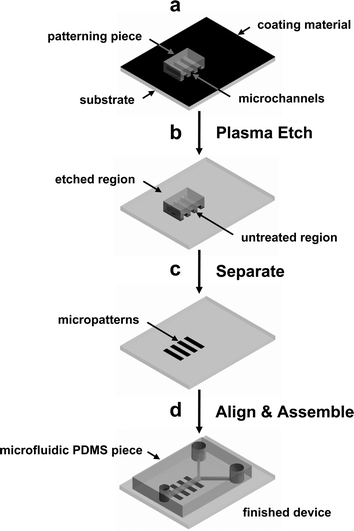 | ||
| Fig. 1 Schematic outline of the procedure for micropatterning cells inside a microfluidic device using cell-adhesive or non-adhesive substrates. (a) A small patterning PDMS piece with embossed surface pattern is placed on a substrate that is coated with a thin film. (b) Exposure to reactive oxygen plasma selectively removes material in regions where the patterning piece does not contact the substrate. (c) After the patterning PDMS piece is removed, well-defined surface micropatterns of cell-adhesive or non-adhesive materials that can be used for selective cell attachment and growth. (d) A microfluidic PDMS piece with microchannel is aligned and bonded to the patterned substrate. The finished device can be used to culture patterned cells inside a microfluidic device. | ||
Fabrication of microfluidic cell culture device
A separate PDMS piece was prepared for microfluidic device fabrication. The microfluidic cell culture device was fabricated in PDMS using rapid prototyping and soft lithography according to published procedures.1,16,17 The master for the neuronal culture device was fabricated by patterning two layers of photoresist.16 Briefly, first layer of photoresist, 3 µm thick was obtained by spinning SU-8 5 (Microchem, Newton, MA) negative photoresist at 3,500 rpm for 60 s. A 20,000 dpi high-resolution printer (CAD/Art Services, San Diego, CA) was used to generate the first transparency mask to create the microchannels (10 µm wide and spaced 50 µm). The transparency mask was used to pattern the SU-8 5 photoresist. Second layer of thick photoresist (100 µm) was spun on top of patterned 3 µm features. SU-8 50 was used as a second layer and spun at 900 rpm for 60 s. Separate, second mask was used to create the chamber areas aligned to the first pattern. After development, the wafer was placed in a clean Petri dish and mixture of PDMS-prepolymer and catalyst (10:1 ratio) was poured over the maser. The Petri dish containing the wafer was placed in an oven for 15 h at 70 °C. Positive replica with embossed microchannels was fabricated by replica-molding PDMS against the master. The inlets and outlets for the fluids were punched out using sharpened blunt-tip needles. The surface of the PDMS replica and a coated glass substrate were activated with reactive oxygen plasma and brought together by visual alignment immediately after activation to form an irreversible seal.22Sterilization and fluidic bonding
The plasma etching/sterilization equipment was placed inside a biological safety cabinet (class 100 clean bench, Envirco, Model 4830, NM) to avoid potential contamination problems. All process steps were carried out in sterile conditions. Performing device assembly inside a biosafety cabinet had additional benefit of reducing particulate contamination. When transporting substrates and materials, they were kept inside sterile containers.Mammalian cell culture
The metastatic human breast cancer cell line MDA-MB 231 (ATTC, MD) was cultured in Leibovitz's L-15 medium (Invitrogen, CA) supplemented with 10% FCS. Primary HUVEC were a gift from Prof. Steven George of UC Irvine. They were cultured in M199 medium supplemented with 10% FCS, heparin (5 U µL−1), 1% endothelial growth factor (Sigma, MO), and antibiotics. The NIH 3T3 mouse fibroblasts were cultured in DMEM containing 10% FCS. Dissociated cells were plated on the patterned substrates at approximate density of 5 × 10³ – 1 × 10⁵ cells cm−2, and cultured in a humidified incubator at 37 °C.Neuronal cell culture
Primary cultures of E18 rat cortical neurons were prepared as described previously.23 Dissociated cells were plated on the PLL treated substrates and in the microfluidic channels at a density of approximately 3 × 10⁴ cells cm−2. The cells were cultured in the neurobasal medium supplemented with 2% B27 and 0.25% GlutaMAX in a humidified incubator (Thermo Forma, OH) at 37 °C with 5% CO2.24 Live neurons were stained with 1 µM calcein AM (Molecular Probes, OR) in the culture medium.Microscopy
Phase-contrast and epifluorescent images were taken using an inverted microscope, Nikon TE 300 (Nikon, NY), CoolSNAPcf CCD camera (Roper Scientific, AZ), and MetaMorph (Universal Imaging, PA). Lambda DG-4 (Spectra Services, NY) was used as an excitation light source which was controlled by MetaMorph. For long term culture on the microscope stage, time-lapse images were acquired every 5 min for 12 h. These images are presented as maximum projections prepared with MetaMorph.Results and discussion
Schematic outline of the procedure developed in this paper is shown in Fig. 1. This method uses reactive oxygen plasma treatment to accomplish both surface patterning and activation of the substrate and PDMS for assembling the microfluidic device. First, a substrate is coated with a thin film of either cell-adhesive or non-adhesive material. We have used PLL, collagen, and other extracellular matrix (ECM) proteins (cell-adhesive) as well as untreated PS and other cell non-adhesive substrates. Poly-L-lysine and collagen are commonly used ECM coating materials in cell biology and are readily available and most biology and chemistry laboratories are familiar with their use.Both microcontact printing (μCP) and micromolding in capillaries (MIMIC) can be used to create micropatterns on the substrates and obtained cellular patterns. One of the most important drawbacks for the above two methods when used for obtaining patterned cells inside microfluidic devices is that reliable seal (bonding) between the substrate and the PDMS microfluidic device could not be obtained. In order for PDMS to bond to a substrate irreversibly, clean surfaces are essential. Surfaces that have been previously modified with SAMs or other organic monolayers and proteins can not be used to bond irreversibly with PDMS. Although those samples may still work when PDMS is placed in conformal contact, there is higher rate of failure and the device can not be pressurized.
Two different pieces of PDMS were prepared for this experiment, a smaller patterning piece (4 × 4 mm2) having to generate the surface pattern and a larger microfluidic piece (20 × 30 mm2) with embedded microchannels for the microfluidic device. The patterning PDMS piece was placed on a large substrate (Fig. 1a) and the entire assembly was placed inside a vacuum plasma chamber (Fig. 1b). A small weight (100 g cm−2) was placed on top of the patterning piece to enhance contact with the substrate and to prevent movement during evacuation of the vacuum chamber. The microfluidic PDMS piece was also placed in the plasma chamber to activate it for bonding. After 60 s of exposure to oxygen plasma, the coated areas not in contact with the patterning piece are completely etched away. This leaves a pattern of cell-adhesive and non-adhesive areas for selective attachment of cells. Because the PLL and collagen coatings form a thin coating (PLL thickness is ∼1 nm, measured with an ellipsometer, comparable to a monolayer of polyelectrolyte film reported previously25), short plasma treatment of 60 s is adequate to completely etch away the coating. For cell non-adhesive substrate like PS, this short exposure to oxygen plasma converts it to oxidized PS (PS-ox) which is hydrophilic and adhesive to cells. Therefore, for cell-adhesive substrates, the region where the patterning piece contact the substrate is protected from the etching plasma and yields a “positive” cellular pattern that is identical to the pattern on the patterning piece (Fig. 1c). In contrast, a “negative” cellular pattern is obtained for a cell non-adhesive substrate after plasma treatment. After a small area of patterned cell-adhesive and non-adhesive is defined on the substrate, the microfluidic PDMS piece can be visually aligned and bonded to complete the device. Because the patterning piece covers a small area, the etched area outside the pattern is activated and can be used to bond the substrate with a microfluidic PDMS piece. (Fig. 1d) The completed device can now be used to culture cells on a micropatterned surface that is enclosed within the microfluidic channels. Although a wide variety of substrates can be patterned using the method described in this work, there are some limitations for ECM proteins that can denature and lose their biological activities when dried. However, these limitations can be overcome by using both cell-adhesive and non-adhesive materials. For example, a substrate can be first coated with cell non-adhesive material (bovine serum albumin, alkylsilane and poly(ethyleneglycol)) and the area exposed to oxygen plasma can be backfilled with a fragile ECM protein after assembling the substrate with the microfluidic PDMS piece.
Although we have not extensively characterized and optimized the patterning conditions, dense and small features take longer time when compared to large, sparse patterns. Etch times and other experimental conditions will need to be adjusted depending on the equipment used. In general, for bonding application, short treatment times at medium power is used (200 mTorr, 10 W, 60 s). Longer plasma treatments at high power result in over-oxidized PDMS surface that do not bond to other surfaces. The plasma treatment times reported in the manuscript (5–120 s) were optimized for PDMS bonding using a basic plasma chamber. For applications that require longer time to etch surface patterns, the plasma-exposure may be divided in two stages that include etching (substrate and masking PDMS) followed by bonding (insert the microfluidic PDMS piece) treatments. For example, if a total of 5 min is needed to etch the substrate, only the substrate is placed in the plasma chamber during the first 3 min followed by substrate and microfluidic PDMS piece in the last 2 min. This approach will minimize plasma exposure for the microfluidic PDMS piece and yield optimal bonding. It will also ensure that the substrate coating is completely removed so that reliable irreversible bonding can be formed.
Fig. 2a and b show fluorescence micrographs of PLL patterns on glass substrates. Fig. 2c and d show phase-contrast micrographs of patterned rat cortical neurons that were cultured for 8 DIV on corresponding PLL patterned substrates. These micrographs clearly show that the neurons spread and send out processes preferentially on the PLL patterned areas. To obtain PLL patterns shown in Fig. 2a and b, PLL coated glass substrates were covered with a square PDMS patterning piece (4 × 4 mm2) with 15 µm wide channels separated by 15 µm spacing (Fig. 2a) and with 25 µm wide channels separated by 25 µm spacing (Fig. 2b) that were 10 µm deep and the entire assembly was exposed to oxygen plasma for 60 s. To visualize the patterned PLL after plasma exposure, FITC reacted with PLL using a previously published method;21 bright regions in the fluorescence micrograph indicate FITC-conjugated PLL, and the dark regions correspond to bare glass where PLL film was removed. The degree of PLL etching was estimated by measuring the fluorescence intensity and line width of FITC-conjugated PLL patterns. When the plasma treatment was short, <30 s, the PLL film was not etched completely and the FITC-conjugated PLL pattern had fluorescent patches in the areas exposed to oxygen plasma. With longer etching, black lines (i.e., etched PLL or bare glass) emerged but the widths of these lines were narrower than expected. When PLL is removed completely from areas exposed to oxygen plasma, they should be devoid of fluorescent patches and the line widths should be identical to the width of the spacing. Because the ratio of line width and spacing was 1:1 for the patterns used in this work, we determined the time required to complete PLL etching by measuring the relative width of the pattern to the spacing. For etch times longer than 60 s the ratio of pattern to spacing remains at unity. Etch time of 60 s was optimum for patterning surface PLL using a patterning piece that was 4 × 4 mm2. For a larger patterning piece (10 × 10 mm2), longer times up to 10 min was needed to obtain complete patterns. The etching experiments were performed with a small weight on top of the patterning piece. Without the weights, slight over-etching of PLL was observed. There was no evidence of over-etching when the weight was used even with longer plasma treatments up to 10 min. For the patterning piece with one end of the lines blocked, as shown in the Fig. 2a and b, clear PLL patterns could be obtained as long as one side was “open”. Channels that were 2 mm long could be etched in 60 s given the dimension of the channels (15 µm wide and 10 µm deep). For longer lines, increasingly longer times were required to obtain complete etching. We have successfully etched channels that were 6 mm long (one side blocked) by etching for 10 min. We have optimized the etching times for the equipment and channel dimensions (width and depth) used in our laboratory. These conditions may need to be optimized depending on the type of plasma etcher and other experimental variables for each situation. The minimum feature of PLL pattern obtained by this method was ∼3 µm (10 µm deep channels separated by 7 µm). Smaller features closer to 1 µm may be patterned but it will require longer plasma treatment.
 | ||
| Fig. 2 Micrographs of patterned PLL lines and primary rat cortical neurons cultured on micropatterned PLL on glass substrates. Bright areas indicate the regions of patterned PLL that were conjugated with FITC for visualization. Fluorescence micrographs of (a) 15 µm wide PLL lines separated by 15 µm spacing and (b) 25 µm wide lines separated by 25 µm spacing. Black regions in these two micrographs indicate etched areas where PLL was removed to expose bare glass. Phase-contrast micrographs of primary rat cortical neurons cultured for 8 DIV on PLL patterned glass substrates containing (c) 15 µm and (d) 25 µm wide lines. The images illustrate that neurons attached and preferentially sent out processes on the PLL patterned areas. | ||
An important issue in using microfluidic devices for cell culture involves sterilizing the assembled device. Routine sterilizing processes such as UV exposure and autoclaving may not be used for microfluidic devices because substrates were coated with biomaterials. The process of bonding microfluidic PDMS piece to a substrate using oxygen plasma treatment can also serve as a sterilization step. We have optimized the plasma treatment time for PLL patterning such that this step can be used for sterilization as well as bonding.
To test the usefulness of plasma-based dry etching, we examined the attachment and growth of three different mammalian cell types. Fig. 3 shows patterned HUVEC, MDA-MB-231 human breast cancer cells and NIH 3T3 mouse fibroblasts cultured for 5–48 h on patterned Petri dishes. We started with non-tissue culture grade Petri dishes and generated patterned cell-adhesive areas on them. Non-tissue culture grade Petri dishes made of PS are usually used for suspension cultures while tissue culture grade PS dishes are used for culturing adherent cells. Physico-chemical properties of oxidized PS surfaces are very similar to tissue culture dishes that are commercially available.26,27 Treatments of non-tissue culture grade PS Petri dishes to reactive oxygen plasma can turn the normally hydrophobic PS surfaces into hydrophilic surfaces, allowing cells to adhere and spread. The effect of patterned exposure of cell non-adhesive PS Petri dish to oxygen plasma is clearly demonstrated by the patterned cells shown in Fig. 3. The cells exhibited preferential attachment and growth on 120 µm wide oxidized areas, whereas the untreated areas (areas where patterning piece contacted the PS substrate) were devoid of cells. All three cell types have similar morphologies to those cultured on control tissue culture grade Petri dishes. Short exposure (2 min) to reactive oxygen plasma effectively changed the PS surface properties and made it cell-adhesive. Longer plasma etching up to 5 min showed similar results. Occasionally, some cells were able to weakly adhere on untreated PS region, but those cells did not spread and remained round, eventually detaching from surface after a day.
 | ||
| Fig. 3 Phase-contrast micrographs of patterned mammalian cells cultured on reactive oxygen plasma treated non-tissue culture grade PS Petri dish. The images show (a) HUVEC cultured for 5 h, (b) MDA-MB-231 breast cancer cells cultured for 36 h, and (c) NIH 3T3 mouse fibroblasts cultured for 48 h on the modified oxidized PS patterns. A small patterning PDMS piece (10 × 10 mm2) with channels (120 µm wide, separated by 80 µm spacing and 100 µm deep) was placed on non-tissue culture grade PS Petri dish. The entire assembly was exposed to oxygen plasma for 2 min. The regions that were exposed to plasma (120 µm wide channels) were oxidized (PS-ox) and became hydrophilic. When cells were added to the modified Petri dish, they preferentially attached, spread, and proliferated on hydrophilic areas exposed to oxygen plasma. | ||
To demonstrate the compatibility of the patterning method with microfluidic device fabrication, we have maintained patterned neurons inside a microfluidic device for 6 DIV. We chose to work with primary rat cortical neurons because they are one of the most difficult cells to culture as they are extremely sensitivity to their culture conditions. Successful demonstration of the approach with the neurons would strongly confirm the validity of the method and indicate that the approach will work with other cell types. A compartmented microfluidic neuronal culture device was fabricated in PDMS to achieve fluidically isolated microenvironments for somas and neurites.16Fig. 4a shows the schematic drawing of the device. Three fluidically isolated compartments (1 mm wide, 7 mm long and 100 µm high) are separated by 100 µm wide barriers as shown. The compartments are connected to each other with a number of microgrooves (3 µm high and 10 µm wide). The size of the microgrooves is sufficiently small that unattached neurons do not pass through the microgrooves to the adjoining compartments during loading. This design simplifies the loading process and allows selective placement of neurons in one compartment. There are large holes at the end of the compartments that serve as cell loading inlets and medium reservoirs for nutrient and gas exchange. The volume in each compartment (without the reservoirs) is less than 1 µL. In comparison, the combined reservoirs for each compartment can hold up to 200 µL. By having such small culture volumes, reagent amounts can be significantly reduced compared to traditional culturing methods. In addition to isolating somas from their processes, we were able to pattern the growth of neurites on the substrate inside the microfluidic device. The microgrooves in the barrier are aligned with micropatterned PLL lines that guide the growth of neuritic processes as shown in Fig. 4b. Micropatterning of the cells and their processes facilitated identification of cells and improves visualization of results. For example, in a random culture on a tissue culture dish, due to the entangled network of dendrites and axons, it is difficult to determine the respective soma for a particular process. Fluorescence micrographs of live, calcein AM stained cells follow patterned PLL, allowing readily identification of cells. This photograph was taken after 6 DIV of culturing neurons inside the microfluidic device. The neurons were initially loaded into the two outer compartments and allowed to send out processes. Two thick black lines are the 100 µm barriers that separate the compartments. As shown, the bright spots indicate that somas are present in the outer two compartments but not the middle. The middle compartment contains neuritic processes that were sent out from the opposite compartments. Fig. 4c shows a series of time-lapse images taken of a pair of processes in the middle compartment projecting from two different neurons in opposite compartments of the device. After approximately 3 to 4 days of growth, neurites from the somal compartment (outer compartments) extend into the neuritic compartment (middle compartment). After 6 DIV, neurites meet in the middle compartment. These micrographs illustrate that the substrate patterning methods can be combined with microfluidic devices to generate controlled microenvironments for different regions of neurons.
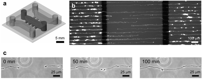 | ||
| Fig. 4 (a) Schematic drawing of a compartmented microfluidic neuronal culture device that was assembled on a PLL micropatterned glass substrate. Three compartments, separated by 100 µm wide barriers, fluidically isolated different neuron regions (soma and neurites were separated from each other). The barriers have embedded microgrooves (3 µm high and 10 µm wide) that allow neurites to grow across the barriers from somal to neuritic compartments. (b) Fluorescence micrograph of rat cortical neurons cultured on PLL patterned glass substrate (25 µm wide lines with 25 µm spacing) inside a compartmented microfluidic neuronal culture device. Neurons were plated into the outer two compartments and cultured for 6 DIV. Live cells were brightly stained by a viability dye, calcein AM. (c) A series of time-lapse images were taken at the middle compartment after 6 DIV of culture. The images show two different processes growing toward each other while respective somas were located in the two outer compartments. The processes follow and remain within the PLL pattern as they extend and eventually meet. | ||
Conclusions
We have developed and tested a plasma-based dry etching approach that enables patterned cell culture inside microfluidic devices. This work demonstrates that surface patterns with minimum feature size of ∼3 µm are possible using plasma-based dry etching. Furthermore, this technique can be used with protein coatings (i.e., ECM) and other organic or inorganic substrates that are not compatible with other patterning methods such as μCP. It has unique advantages over standard micropatterning methods as it combines microfluidic cell culture devices and patterned substrates. The plasma treatment is used to pattern the substrate, sterilize, and bond the microfluidic device, combining several steps. This technique may be used for a broad range of applications in neuroscience and cell biology research as demonstrated with patterned primary central neurons inside a compartmented microfluidic device for 6 DIV.Acknowledgements
The Institute for Brain Aging and Dementia thanks NIA (AG 17765).References
- G. M. Whitesides, E. Ostuni, S. Takayama, X. Jiang and D. E. Ingber, Annu. Rev. Biomed. Eng., 2001, 3, 335 Search PubMed.
- C. S. Chen, M. Mrksich, S. Huang, G. M. Whitesides and D. E. Ingber, Science, 1997, 276, 1425 CrossRef CAS.
- S. Zhang, L. Yan, M. Altman, M. Lässle, H. Nugent, F. Frankel, D. A. Lauffenburger, G. M. Whitesides and A. Rich, Biomaterials, 1999, 20, 1213 CrossRef CAS.
- Y. Ito, Biomaterials, 1999, 20, 2333 CrossRef CAS.
- R. Kane, S. Takayama, E. Ostuni, D. E. Ingber and G. M. Whitesides, Biomaterials, 1999, 20, 2363 CrossRef.
- E. Ostuni, R. S. Kane, C. S. Chen, D. E. Ingber and G. M. Whitesides, Langmuir, 2000, 16, 7811 CrossRef CAS.
- L. Lauer, C. Klein and A. Offenhäusser, Biomaterials, 2001, 22, 1925 CrossRef CAS.
- A. Bernard, D. Fitzli, P. Sonderegger, E. Delamarche, E. Michel, H. R. Bosshard and H. Biebuyck, Nat. Biotechnol., 2001, 19, 866 CrossRef CAS.
- D. J. Beebe, G. A. Mensing and G. M. Walker, Annu. Rev. Biomed. Eng., 2002, 4, 261 Search PubMed.
- S. Takayama, E. Ostuni, P. LeDuc, K. Naruse, D. E. Ingber and G. M. Whitesides, Chem. Biol., 2003, 10, 123 CrossRef CAS.
- A. Folch, B.-H. Jo, O. Hurtado, D. J. Beebe and M. Toner, J. Biomed. Mater. Res., 2000, 52, 346 CrossRef CAS.
- N. L. Jeon, H. Baskaran, S. K. W. Dertinger, G. M. Whitesides, L. Van De Water and M. Toner, Nat. Biotechnol., 2002, 20, 826 CAS.
- S. K. W. Dertinger, X. Jiang, Z. Li, V. N. Murthy and G. M. Whitesides, Proc. Natl. Acad. Sci., 2002, 99, 12542 CrossRef CAS.
- P. Thiébaud, L. Lauer, W. Knoll and A. Offenhäusser, Biosens. Bioelectron., 2002, 17, 87 CrossRef CAS.
- G. M. Walker, M. S. Ozers and D. J. Beebe, Biomed. Microdevices, 2002, 4, 161 CrossRef CAS.
- A. M. Taylor, S. W. Rhee, C. H. Tu, D. H. Cribbs, C. W. Cotman and N. L. Jeon, Langmuir, 2003, 19, 1551 CrossRef CAS.
- Y. Xia and G. M. Whitesides, Angew. Chem. Int. Ed., 1998, 37, 550 CrossRef CAS.
- A. Tourovskaia, T. Barber, B. T. Wickes, D. Hirdes, B. Grin, D. G. Castner, K. E. Healy and A. Folch, Langmuir, 2003, 19, 4754 CrossRef CAS.
- J. P. Bearinger, D. G. Castner, S. L. Golledge, A. Rezania, S. Hubchak and K. E. Healy, Langmuir, 1997, 13, 5175 CrossRef CAS.
- G. Banker and K. Golsin, Culturing Nerve Cells, The MIT Press, Cambridge, 2nd ed., 1998, ch. 13 Search PubMed.
- V. Schnaible and M. Przybylski, Bioconjugate Chem., 1999, 10, 861 CrossRef CAS.
- D. C. Duffy, J. C. McDonald, O. J. A. Schueller and G. M. Whitesides, Anal. Chem., 1998, 70, 4974 CrossRef CAS.
- K. J. Ivins, E. T. N. Bui and C. W. Cotman, Neurobiol. Dis., 1998, 5, 365 CrossRef CAS.
- G. J. Brewer, J. Neurosci. Meth., 1997, 71, 143 Search PubMed.
- S. S. Shiratori and M. F. Rubner, Macromolecules, 2000, 33, 4213 CrossRef CAS.
- J.-L. Dewez, J.-B. Lhoest, E. Detrait, V. Berger, C. C. Dupont-Gillain, L.-M. Vincent, Y.-J. Schneider, P. Bertrand and P. G. Rouxhet, Biomaterials, 1998, 19, 1441 CrossRef CAS.
- E. Detrait, J.-B. Lhoest, B. Knoops, P. Bertrand and P. van den Bosch de Aguilar, J. Neurosci. Meth., 1998, 84, 193 Search PubMed.
| This journal is © The Royal Society of Chemistry 2005 |