Real time quantitative Raman spectroscopy of supported metal oxide catalysts without the need of an internal standard
S. J.
Tinnemans
,
M. H. F.
Kox
,
T. A.
Nijhuis
,
T.
Visser
and
B. M.
Weckhuysen
*
Department of Inorganic Chemistry and Catalysis, Debye Institute, Utrecht University, Sorbonnelaan 16, 3508 TB, Utrecht, The Netherlands. E-mail: b.m.weckhuysen@chem.uu.nl.; Fax: +31 30 2511027; Tel: +31 30 2534328
First published on 18th November 2004
Abstract
In continuation to the possibility of using a combined operando Raman/UV-Vis-NIR set-up for conducting qualitative Raman spectroscopy, the possibilities for quantitative Raman spectroscopic measurements of supported metal oxide catalysts under working conditions without the need of an internal standard have been explored. The dehydrogenation of propane over an industrial-like 13 wt% Cr/Al2O3 catalyst was used as a model system. During reaction, the catalytic solid was continuously monitored by both UV-Vis-NIR and Raman spectroscopy. As the dehydrogenation proceeds, the catalyst gradually darkens due to coke formation and consequently the UV-Vis-NIR diffuse reflectance and Raman scattered signal progressively decrease in intensity. The formation of coke was confirmed with TEOM, TGA and Raman. The measured Raman spectra can be used as a quantitative measure of the amount of carbonaceous deposits at the catalyst surface provided that a correction factor G(R∞) is applied. This factor can be directly calculated from the corresponding UV-Vis-NIR diffuse reflectance spectra. The validity of the approach is compared with one, in which an internal boron nitride standard is added to the catalytic solid. It will be shown that the proposed methodology allows measurement of the amount of carbonaceous deposits on a catalyst material inside a reactor as a function of reaction time and catalyst bed height. As a consequence, an elegant technique for on-line process control of e.g. an industrial propane dehydrogenation reactor emerges.
Introduction
Recent technical developments have tremendously increased the popularity of Raman spectroscopy as a characterization tool to obtain physico-chemical information on heterogeneously catalyzed reaction systems.1–17 Most characterization studies based on Raman spectroscopy, however, are still applied qualitatively, since besides the concentration of the scattering species, variations in laser excitation intensity, instrumental settings, sample positioning, temperature fluctuations, etc. all may influence the Raman intensities. Furthermore, Raman intensities depend on the scattering and absorption properties of the catalytic solid. As a consequence, progressive darkening of the catalyst during reaction by e.g. coke formation may strongly affect the intensities of the Raman spectra.One way to quantify Raman spectra is by normalizing the Raman bands of a species of interest to those of a specific scattering species, which is assumed to remain unaffected with reaction time. In principle, for supported metal oxide catalysts, the Raman bands of the bulk support material can be used. However, it should be noted that this is only true if the intensity of the bulk material is not influenced by changes in its surroundings. Different loadings of a catalyst would change the coverage of bulk material and therefore result in different band intensities of this bulk, while coverage of the bulk material by for instance coke would also affect the ‘visible amount’ of bulk material.
Alternatively, an unreactive standard of known concentration may be mixed homogeneously with the catalyst. Such internal standards should not interact with the catalyst material, or perturb or overlap the spectrum of the supported metal oxide catalyst. Internal standards should also be strong Raman scatterers, so that a small quantity produces a signal of adequate intensity. Boron nitride (BN) may be such a standard material since it exhibits only one intense and strong Raman band at 1367 cm−1, while the vibrational bands of most supported metal oxides appear below 1200 cm−1. Several successful applications of an internal standard are available in the literature.18–23
It is known that the scattering and absorption properties of a catalytic solid can be described by the diffuse reflectance R∞ of the solid, as measured with UV-Vis-NIR spectroscopy.24–27 Progressive darkening of the catalytic solid due to e.g. coke formation during reaction leads to a decreasing R∞ and the proportionality between the Raman band intensities and the concentration of the corresponding species is no longer valid. In order to compare Raman intensities at different times-on-stream inside a catalytic reactor, the relationship between the diffuse reflectance of the catalytic solid of infinite thickness (R∞) and the Raman intensity (Ψ∞) must be known. As early as 1967 Schrader and Bergmann28 derived an approximate expression to correlate the Raman intensity Ψ∞ to the diffuse reflectance R∞ based on the Kubelka–Munk formalism. This was later improved by Waters29 and Kuba and Knozinger30 into the following expression:
 | (1) |
 | (2) |
 | ||
| Fig. 1 G(R∞) as a function of R∞. The insert represents the change of G(R∞) as function of the reaction time in our experiments. | ||
However, with this set-up, one should be able to apply Raman spectroscopy not only in a qualitative, but also in a quantitative manner since the G(R∞) of the catalytic solid can be simultaneously measured as a function of reaction time. The goal of this work is to explore the possibilities of the developed set-up for performing quantitative Raman spectroscopy taking the dehydrogenation of propane over an industrial-like Cr/Al2O3 dehydrogenation catalyst as a case study. The developed methodology will be compared with the use of BN as an internal standard and it will be shown that the experimental set-up is very suitable for Raman quantitation. We believe it can be generally applied for studying supported metal oxide catalysts in a quantitative manner under working conditions.
Experimental
A detailed description of the two experimental UV-Vis-NIR/Raman set-ups used and the catalyst material under investigation, an industrial-like 13 wt% Cr/Al2O3 alkane dehydrogenation catalyst, can be found in recent publications of Nijhuis et al.31,32 The catalyst was ballmilled for 15 min together with the internal standard BN (Aldrich, 99%) in a 20∶1 ratio to obtain a homogeneously mixed powder. The furnace of the reactor was heated to 585 °C (catalyst temperature of 550 °C) with 10 °C min in a 20 vol% oxygen (Hoek Loos, 99.995%) in He (Hoek Loos, 99.996%) flow of 15 ml min−1. After heating, He was purged to remove all oxygen in the system and subsequently a 9 vol% propane (Hoek Loos, 99.92%) stream with a total flow of 22 ml min−1 was applied. All flows given are at standard temperature and pressure. On-line gas analysis was performed using a Varian CP-4900 Micro GC equipped with a Poraplot Q and a Molsieve 5A column and TCD detectors. UV-Vis-NIR diffuse reflectance (DRS) spectra were measured using a DH-2000 light source (Avantes) combined with an Avaspec 2048 CCD spectrometer (Avantes) and a BI-FL400 high temperature resistant probe (Ocean Optics). Raman spectra were recorded using a Kaiser RXN spectrometer equipped with a 532 nm diode laser (output power of 70 mW). A 5.5” objective was used for beam focusing and collection of the scattered radiation. Further details about the spectroscopic equipment used can be found elsewhere.31 With the experimental set-up described by Nijhuis et al.32 carbon deposits could be measured as a function of the catalyst bed height during and after propane dehydrogenation. All Raman spectra were first baseline-corrected in the spectral region 1100–1700 cm−1 using Thermo Galactic Grams AI v. 7.0 software. This software package was also used to determine Raman peak areas. Tapered element oscillating microbalance (TEOM) experiments have been performed with Rupprecht & Pataschnick TEOM 1500 PMA equipment using 100 mg of catalyst and a gas mixture of propane (7 ml min−1, Hoek Loos, 99.92%)) and argon (20 ml min−1, Hoek Loos, 99.995%). Prior to the uptake experiment, the catalytic solid was dried and calcined under oxygen (5 ml min−1, Hoek Loos, 99.995%) and argon (10 ml min−1, Hoek Loos, 99.995%) at 600 °C. The start of the uptake experiment (t = 0) was defined as the last data point before the first mass change. All mass changes were corrected for gas density- and temperature-effects by performing a blank run over a reactor filled with quartz chips. Thermogravimetric analysis (TGA) has been performed using a Mettler Toledo TGA/SDTA 851e instrument.Results and discussion
1. Combined operando Raman/UV-Vis-NIR spectroscopy and on-line activity measurements of a 13 wt% Cr/Al2O3 propane dehydrogenation catalyst, mixed with an internal boron nitride standard
Figs. 2 and 3 show a representative set of time-resolved Raman and UV-Vis-NIR spectra of an industrial-like 13 wt% Cr/Al2O3 propane dehydrogenation catalyst mixed with an internal standard (BN) under working conditions at 550 °C. The corresponding activity and selectivity data are given in Fig. 4. It can be concluded from Fig. 2 that the Raman band of BN, located at 1350 cm−1 (slightly shifted from the 1367 cm−1 position due to temperature effects) decreases in intensity and seems to broaden when the reaction proceeds. This is due to the formation of coke as new Raman bands arise immediately after the propane dehydrogenation cycle started. These new broad bands are located at 1580 cm−1 and at 1330 cm−1, the latter very close to the Raman band position of the BN standard. These two Raman bands can be assigned based on literature data of relevant reference compounds to the gradual formation of polyaromatic compounds.33–38 However, as coke is expected to be developing throughout the reaction, the amount of coke should increase over time, resulting in increasing intensities of the Raman bands at 1580 and 1330 cm−1. However, this is clearly not observed in Fig. 2. Based on the integrated band intensities the amount of coke (as represented by the intensity of the 1580 cm−1 band) seems to increase up to 30 min (Fig. 2e) followed by a gradual decrease. It is very unlikely that the amount of coke first increases and later on decreases during a propane dehydrogenation cycle. In order to validate this hypothesis we have performed TEOM experiments on the same catalytic solid under experimental conditions, very close to those used in our operando Raman/UV-Vis-NIR reactor set-up. The obtained data are summarized in Fig. 5. It was found that the mass of the catalyst during a propane dehydrogenation cycle at 550 °C gradually increases with increasing reaction time up to 40 min-on-stream and then remains constant.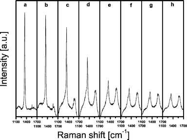 | ||
| Fig. 2 Operando Raman spectra of a 13 wt% chromium-on-alumina catalyst measured during 90 min of propane dehydrogenation at 550 °C. Representative spectra are taken after (a) 0 min, (b) 5 min, (c) 10 min, (d) 15 min, (e) 30 min, (f) 45 min, (g) 60 min and (h) 90 min. | ||
 | ||
| Fig. 3 Operando UV-Vis-NIR diffuse reflectance spectra simultaneously measured from the opposite site of the reactor on a 13 wt% chromium-on-alumina catalyst measured during 90 min of propane dehydrogenation at 550 °C. Representative spectra are taken after (a) 0 min, (b) 5 min, (c) 10 min, (d) 15 min, (e) 30 min, (f) 45 min, (g) 60 min and (h) 90 min. | ||
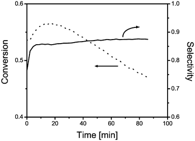 | ||
| Fig. 4 On-line activity and selectivity data for a 13 wt% chromium-on-alumina catalyst plotted against time-on-stream for a propane dehydrogenation cycle at 550 °C. | ||
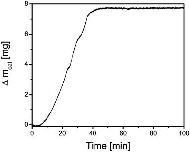 | ||
| Fig. 5 Mass uptake of a 13 wt% chromium-on-alumina catalyst as a function of time-on-stream as measured with TEOM. | ||
A possible explanation for the anomalous behavior of the intensity of the Raman spectra is a gradual darkening of the catalytic solid during propane dehydrogenation, which results in two effects, namely (1) absorption of the incoming laser light and (2) absorption of the Rayleigh and Raman scattered light (self-absorption). This assumption can be verified by analyzing the corresponding UV-Vis-NIR diffuse reflectance spectra (Fig. 3). Fig. 3a represents the spectrum of the catalytic solid just before switching to a stream of propane at 550 °C. At this starting point, the d–d transition of supported Cr2O3-like oxides is clearly visible at around 15 700 cm−1.39,40 A sharp band at 18 800 cm−1 (532 nm) is also observed due to the Raman laser light picked up by the UV-Vis-NIR detector.
The reduction of initially present Cr6+ to Cr3+ in the beginning of the reaction is presented in Fig. 3a and 3b. Fig. 3b–g show a decrease in the diffuse reflectance of the catalytic solid as propane dehydrogenation proceeds. This decrease is due to a darkening of the catalyst and the absorption band of Cr2O3-like oxides almost broadens beyond detection. This is not surprising since the Raman spectra show that carbonaceous species are formed at the active catalyst surface during reaction. This results in a gradual coverage of the supported Cr2O3-like oxides, which are becoming less accessible to the UV-Vis-NIR and Raman laser probing the catalyst. Finally, Fig. 4 shows the on-line activity measurements of the catalytic solid under investigation. It is clear that the propane conversion increases with reaction time to reach a maximum activity of 56% after 17 min and then gradually decreases with increasing time-on-stream. At the same time, the selectivity towards propene slightly increases and reaches a rather stable value of about 87%.
2. Quantitation of operando Raman spectra based on the G(R∞) correction factor and an internal boron nitride standard
As stated in the Introduction, two different approaches to quantify the time-resolved Raman spectra are compared in this work. The first method makes use of a correction factor based on the UV-Vis-NIR diffuse reflectance spectra, further denoted as the G(R∞) correction factor. This correction factor is determined for each Raman spectrum by calculating the G(R∞) value using eqn. (2) at 580 nm (580–532 nm ≈ 18 800–17 200 cm−1 ≈ 1580 cm−1) as illustrated in Fig. 3. This position in the UV-Vis-NIR spectrum corresponds to the coke band at a Raman shift of 1580 cm−1 in case a Raman laser wavelength of 532 nm (18 800 cm−1) is used. The values of G(R∞), calculated from the spectra of which a selection is shown in Fig. 3, are included as an insert in Fig. 1. We found that R∞ and thus G(R∞) are decreasing as the reaction time proceeds except for the first minutes-on-stream. Here, the reduction of Cr6+ to Cr3+ is mainly responsible for a small increase in G(R∞). Both a reduction and blackening of the catalyst influence the color. However, this does not influence the correctness of the G(R∞) values since G(R∞) is only dependant on the color of the catalyst. So, the origin of this changing color does not matter. Although R∞ only drops from values of around 0.35 to 0.19, still this corresponds with a decrease of G(R∞) of more than 50%.In a second step, the corresponding Raman spectra of Fig. 2 were divided by the corresponding values of G(R∞) according to eqn. (1) to obtain the true Raman intensities. The result of this mathematical operation is shown in Fig. 6. It is evident that the Raman bands due to coke formation at 1580 and 1330 cm−1 gradually develop as a function of reaction time, while the Raman band of BN decreases during the first 30 min (Fig. 6a–e) and remains constant thereafter. On the other hand, Fig. 7 shows the Raman spectra of Fig. 2 obtained after normalizing the Raman bands of the carbonaceous deposits to those of the inert internal standard BN. Here, a shoulder next to the BN Raman band readily appears at around 1330 cm−1 due to the formation of coke and this band grows in intensity during the whole dehydrogenation period indicating that the amount of coke increases. It is also clear that the coke band at 1580 cm−1 is more pronounced than in Fig. 6.
 | ||
| Fig. 6 G(R∞) corrected Raman spectra from Fig. 2 measured on a 13 wt% chromium-on-alumina catalyst during 90 min of propane dehydrogenation. Representative spectra are taken after (a) 0 min, (b) 5 min, (c) 10 min, (d) 15 min, (e) 30 min, (f) 45 min, (g) 60 min and (h) 90 min. | ||
 | ||
| Fig. 7 BN corrected Raman spectra from Fig. 2 measured on a 13 wt% chromium-on-alumina catalyst measured during 90 min of propane dehydrogenation. Representative spectra are taken after (a) 0 min, (b) 5 min, (c) 10 min, (d) 15 min, (e) 30 min, (f) 45 min, (g) 60 min and (h) 90 min. | ||
In order to compare the two quantitation methods, the integrated Raman peak intensities of the coke band at 1580 cm−1 are plotted against reaction time in Fig. 8, together with those obtained from the original Raman spectra. Similar results have been obtained for the 1330 cm−1 band, but because this band overlaps with the Raman BN peak the values are more scattered. The relative amounts measured with Raman spectroscopy have been transformed into the exact amount of coke present in the solid by measuring the catalyst samples after reactions with TGA. This allows us to put real values to the amount of coke in the catalyst sample as a function of reaction time. It is evident that without any correction applied the band intensities do not reflect the reality as the amount of coke seems to go through a maximum. An observation, which is clearly in contrast with the TEOM data. Instead, the data obtained after applying one of the correction methods results in coke uptake patterns, very similar to those obtained with the TEOM technique. Indeed, quantitative Raman spectroscopy indicates that a maximum amount of coke is formed after about 40–50 min-on-stream. The small differences between the TEOM method and both Raman quantitation methods should be entirely related to the different reactor designs used.
 | ||
| Fig. 8 Intensity profile of the 1580 cm−1 Raman band during propane dehydrogenation without any correction (■), after G(R∞) correction (▲) and after BN based correction (●). | ||
3. Combined operando Raman/UV-Vis-NIR spectroscopy and on-line activity measurements of a 13 wt% Cr/Al2O3 propane dehydrogenation catalyst, without using an internal boron nitride standard
Since the Raman BN peak at 1350 cm−1 overlaps with the coke band at 1330 cm−1 we have applied the same methodology to a catalyst sample without BN. The obtained catalytic performances are shown in Fig. 9. It was found that the selectivity towards propene readily reaches a value around 92%, while the conversion increases to a maximum value of about 50% after 34 min-on-stream. Trendwise these results are very similar to those obtained for a catalyst containing BN, although the exact maxima are not identical. | ||
| Fig. 9 Activity and selectivity data of the 13 wt% chromium-on-alumina catalyst without BN, as well as the intensity profile of the G(R∞) corrected 1330 cm−1 and 1580 cm−1 Raman bands. | ||
Based on the Raman spectra measured and by applying the G(R∞) correction factor one can quantify the 1330 and 1580 cm−1 bands. The obtained results are included in Fig. 9. The relative ratio of the intensities of the 1330 and 1580 cm−1 Raman bands gradually increases with increasing time-on-stream and reaches a maximum after 34 min-on-stream, after which a gradual but slow decrease takes place. This maximum and decrease almost coincide with the corresponding conversion plot. This indicates that after 34 min on stream the nature of the coke is becoming more graphitic.33–38,41,42 In other words, it seems that the initial coke formed is beneficial for the propane dehydrogenation as the propane conversion increases with increasing coke content. After 34 min-on-stream a maximum conversion has been reached, however at this point, the type of coke is changing towards graphite, which is detrimental to the catalyst performance. Thus, a plausible explanation for the activity data is that coke is formed and facilitates the adsorption of propane near the active propane dehydrogenation site; as the reaction proceeds this results in more coke formation, which finally blocks the dehydrogenation site due to graphitisation.
4. Coke profiles as a function of the catalyst bed height
In another experiment we have measured the Raman spectra during a propane dehydrogenation cycle as a function of the catalyst bed height. The corresponding G(R∞) corrected Raman spectra obtained after 250 min-on-stream are given in Fig. 10 and both 1580 and 1330 cm−1 Raman bands are clearly visible. As expected the relative intensity of the Raman spectra increases from top (reactor inlet) to bottom (reactor outlet). After the dehydrogenation cycle the catalyst was removed from the reactor and the amount of coke was determined by TGA at different bed heights. These amounts should correspond according to our methodology with the integrated intensity of the G(R∞) corrected Raman spectra. The result is shown in Fig. 11. As expected there is a good correlation between the amount of coke quantified with Raman spectroscopy and the amount of coke independently measured with TGA. According to this plot the error in our measurements is close to 10%. The experiment also illustrates that propene formed during reaction seems to be the precursor for the coke made at the catalyst surface.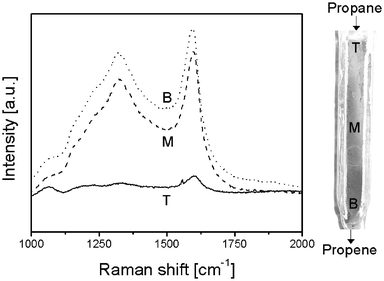 | ||
| Fig. 10 G(R∞) corrected Raman spectra at different positions in the reactor after 250 min of propane dehydrogenation at 550 °C. The spectra were taken at the top (solid), middle (dashes) and bottom (dots) of the reactor. | ||
 | ||
| Fig. 11 G(R∞) corrected Raman intensity of the 1580 cm−1 band versus the amount of coke as measured with TGA for different reactor bed heights. | ||
5. Evaluation of Raman quantitation based on the G(R∞) correction factor
The proposed method provides an elegant and a more generally applicable procedure to determine in a quantitative manner the amount of surface species measured with Raman spectroscopy inside a catalytic reactor as a function of the reaction time and catalyst bed height. The main advantage of the developed method is that no additional compound is required to quantify the measured Raman spectra. In this particular set of experiments, boron nitride, although catalytically inert, is not a good internal standard since its Raman peak clearly overlaps with one of the coke bands. In general, all methods of referencing to an internal standard are highly specific to the systems to which they are applied.The assumption for Raman quantitation using the G(R∞) correction factor is that the scattering coefficient s is constant during the experiment. This means that quantitation is possible within one experiment, but not straightforward when different catalyst samples in different runs are compared. The developed approach also shows excellent potential for remote sensing applications. More in particularly, to monitor on-line the amount of coke in e.g. an industrial propane dehydrogenation reactor at different positions in the reactor bed. Our data illustrates that coke deposits are beneficial for propene formation as long as the amount of coke is not too high and has not been transformed into graphite-like coke deposits. In other words, the developed technique is ideally suited for developing an expert system to control this catalytic process on the basis of spectroscopic data. The amount and type of coke can then be monitored by using Raman spectroscopy and the obtained data are analyzed in a quantitative manner with the aid of UV-Vis-NIR diffuse reflectance spectroscopy. The latter technique, in addition, allows us to detect on the basis of the position of the d–d transitions of supported Cr3+ long-term deactivation phenomena (ruby formation).40
Conclusions
Two different methods of Raman quantitation, namely the use of an internal boron nitride standard and a diffuse reflectance correction factor have been explored in order to determine the amount of coke present in a catalytic reactor during a propane dehydrogenation cycle. It was found that both approaches are suitable, but the use of a combined operando Raman/UV-Vis-NIR set-up clearly has the advantage that no additional compounds have to be added to the catalytic system under investigation. Comparing the results to TGA/TEOM data has proven the validation of the method. They all are in good agreement with each other. The new method, in which a UV-Vis correction factor is applied, allows with an estimated error of 10% to quantify the amount of coke formed in a propane dehydrogenation reactor as a function of catalyst bed height as well as reaction time. The tools are now in place to develop an expert system for spectroscopic control of an industrial propane dehydrogenation reactor.It was also found that propene is the precursor for coke formation at the catalyst surface and the first coke made is beneficial for propane dehydrogenation. This is due to a facilitated adsorption of propane. As the reaction proceeds, the increased amount of coke formed in the neighbourhood of the alkane dehydrogenation sites becomes more graphitic, preventing the formation of propene and as a consequence the activity drops. Thus, the amount of coke formed seems to be critical for the catalyst performance.
Acknowledgements
The authors acknowledge B. van der Linden (Delft University of Technology) and F. Broersma (Utrecht University) for performing TGA and TEOM measurements, respectively. T. A. N. acknowledges financial support by the Dutch National Science Foundation (NWO-STW-VIDI grant). The research of B. M. W. is supported by Van der Leeuw and VICI grants of NWO-CW and by NRSC-Catalysis. The research is part of a COST action (D15/0021/01) and CONCORDE network sponsored by the European Union.References
- M. A. Banares, in In-situ Spectroscopy of Catalysts, ed. B. M. Weckhuysen, American Scientific Publishers, Stevenson Ranch, CA, USA, 2004, p. 59 Search PubMed.
- M. A. Banares, M. O. Guerrero-Perez, J. L. G. Fierro and G. G. Cortez, J. Mater. Chem., 2002, 12, 3337 RSC.
- M. A. Banares and I. E. Wachs, J. Raman Spectrosc., 2002, 33, 359 CrossRef CAS.
- S. Bordiga, A. Damin, F. Bonino, G. Ricchiardi, C. Lamberti and A. Zecchina, Angew. Chem., Int. Ed., 2002, 41, 4737 CrossRef.
- G. Le Bourdon, F. Adar, M. Moreau, S. Morel, J. Reffner, A. S. Mamede, C. Dujardin and E. Payen, Phys. Chem. Chem. Phys., 2003, 5, 4441 RSC.
- M. Arab, D. Bougeard, J. M. Aubry, J. Marko, J. F. Paul and E. Payen, J. Raman Spectrosc., 2002, 33, 390 CrossRef CAS.
- H. Knozinger and G. Mestl, Top. Catal., 1999, 8, 45 CrossRef CAS.
- G. Mestl, J. Mol. Catal. A: Chem., 2000, 158, 45 CrossRef CAS.
- M. Dieterle, G. Weinberg and G. Mestl, Phys. Chem. Chem. Phys., 2002, 4, 812 RSC.
- M. Dieterle and G. Mestl, Phys. Chem. Chem. Phys., 2002, 4, 822 RSC.
- G. Mestl, J. Raman Spectrosc., 2002, 33, 333 CrossRef CAS.
- P. C. Stair, Curr. Opin. Solid State Mater. Sci., 2001, 5, 365 CrossRef CAS.
- Y. T. Chua and P. C. Stair, J. Catal., 2000, 196, 66 CrossRef CAS.
- P. C. Stair and C. Li, J. Vacuum Sci. Technol. A: Vacuum Surf. Films, 1997, 15, 1679 Search PubMed.
- M. J. Li, Z. C. Feng, P. L. Ying, Q. Xin and C. Li, Phys. Chem. Chem. Phys., 2003, 5, 5326 RSC.
- I. E. Wachs, Top. Catal., 1999, 8, 57 CrossRef CAS.
- S. B. Xie, E. Iglesia and A. T. Bell, J. Phys. Chem. B, 2001, 105, 5144 CrossRef CAS.
- S. S. Chan, I. E. Wachs and L. L. Murrell, J. Catal., 1984, 90, 150 CrossRef CAS.
- J. P. Baltrus, L. E. Makovsky, J. M. Stencel and D. M. Hercules, Anal. Chem., 1985, 57, 2500 CrossRef CAS.
- X. Zheng, W. Fu, S. Albin, K. L. Wise, A. Javey and J. B. Cooper, Appl. Spectrosc., 2001, 55, 382–388 CrossRef CAS.
- T. Vankeirsbilck, A. Vercauteren, W. Baeyens, G. Van der Weken, F. Verpoort, G. Vergote and J. P. Remon, Trends Anal. Chem., 2002, 21, 869–877 CrossRef CAS.
- K. J. Schmidt, S. L. Zhang, K. H. Michaelian, M. A. Webb and G. R. Loppnow, Appl. Spectrosc., 1999, 53, 1206–1211 CrossRef CAS.
- J. A. Bergwerff, T. Visser, B. R. G. Leliveld, B. D. Rossenaar, K. P. de Jong and B. M. Weckhuysen, J. Am. Chem. Soc., 2004, 126, 14548–14556 CrossRef CAS.
- R. A. Schoonheydt, in Characterization of Heterogeneous Catalysts, ed. F. Delannay, Marcel Dekker, Inc., New York and Basel, 1984 Search PubMed.
- G. Kortum, Reflectance Spectroscopy: Principles, Methods and Applications, Springer-Verlag, Berlin, Heidelberg and New York, 1969 Search PubMed.
- R. Kellerman, in Spectroscopy in Heterogeneous Catalysis, ed. W. N. Delgass, G. L. Haller, R. Kellerman and J. H. Lunsford, Academic Press, New York, 1979, p. 86 Search PubMed.
- B. M. Weckhuysen, in In-situ Spectroscopy of Catalysts, ed. B. M. Weckhuysen, American Scientific Publishers, Stevenson Ranch, CA, USA, 2004, p. 255 Search PubMed.
- B. Schrader and G. Z. Bergmann, Anal. Chem, 1967, 225, 230 CrossRef CAS.
- D. N. Waters, Spectrosc. Acta, Part A: Mol. Biomol. Spectrosc., 1994, 50, 1833 Search PubMed.
- S. Kuba and H. Knozinger, J. Raman Spectrosc., 2002, 33, 325 CrossRef CAS.
- T. A. Nijhuis, S. J. Tinnemans, T. Visser and B. M. Weckhuysen, Phys. Chem. Chem. Phys., 2003, 5, 4361 RSC.
- T. A. Nijhuis, S. J. Tinnemans, T. Visser and B. M. Weckhuysen, Chem. Eng. Sci., 2004 Search PubMed , in press.
- Y. T. Chua and P. C. Stair, J. Catal., 2003, 213, 39 CrossRef.
- S. Mertes, B. Dippel and A. Schwarzenbock, J. Aerosol Sci., 2004, 35, 347–361 CrossRef CAS.
- G. Compagnini, O. Puglisi and G. Foti, Carbon, 1997, 35, 1793 CrossRef CAS.
- R. Escribano, J. J. Sloan, N. Siddique, N. Sze and T. Dudev, Vib. Spectrosc., 2001, 26, 179 CrossRef CAS.
- S. K. Sze, N. Siddique, J. J. Sloan and R. Escribano, Atmos. Environ., 2001, 35, 561 CrossRef CAS.
- F. Kong, R. Kostecki, G. Nadeau, X. Song, K. Zaghib, K. Kinoshita and F. McLarnon, J. Power Sources, 2001, 97–8, 58 CrossRef.
- R. L. Puurunen and B. M. Weckhuysen, J. Catal., 2002, 210, 418 CrossRef CAS.
- B. M. Weckhuysen, I. E. Wachs and R. A. Schoonheydt, Chem. Rev., 1996, 96, 3327 CrossRef CAS.
- M. A. Montes-Moran and R. J. Young, Carbon, 2002, 40, 845 CrossRef CAS.
- G. Mul, M. A. Banares, G. Garcia Cortez, B. van der Linden, S. J. Khatib and J. A. Moulijn, Phys. Chem. Chem. Phys., 2003, 5, 4378 RSC.
| This journal is © the Owner Societies 2005 |