Studies on performance degradation of a direct methanol fuel cell (DMFC) in life test
Jianguo
Liu
,
Zhenhua
Zhou
,
Xinsheng
Zhao
,
Qin
Xin
,
Gongquan
Sun
and
Baolian
Yi
*
Direct Alcohol Fuel Cell Laboratory, Dalian Institute of Chemical Physics, CAS, P.O. Box 110, 116023, Dalian, China. E-mail: blyi@dicp.ac.cn; Fax: 86-411-4684839; Tel: 86-411-4379097
First published on 1st December 2003
Abstract
A 75 h life test of a direct methanol fuel cell (DMFC) at a low current density of 100 mA cm−2 was carried out. Electrochemical impedance spectroscopy (EIS), scanning electron microscopy (SEM) and transmission electron microscopy (TEM) were applied to characterize the membrane electrode assembly (MEA) during the life test. The EIS results showed that the high frequency cell impedance of the MEA increased from 0.26 ohm cm2 at the beginning of the life test to 0.37 ohm cm2 at the end. SEM images of the MEA in cross-section apparently demonstrated the delamination of the electrodes from the membrane after the life test. TEM analysis of the electrocatalysts in the pre- and post-test cell revealed that the agglomeration of the metal particles in the anode was more serious than in the cathode. The results indicate that the agglomeration of electrocatalysts together with the delamination of the MEA concurrently contribute to the performance degradation of the DMFC.
Introduction
There is growing interest in the research of direct methanol fuel cells (DMFCs) as portable power sources and electric devices due to their high energy density and simplicity in structure such as easy storage and supply of fuel, without need of reforming and humidification.1–3 Presently, the performance of state-of-the-art membrane and electrode assemblies (MEAs) in DMFCs can compete favorably with hydrogen-fueled and on-board reforming fuel cell systems.4 However, the long-term stability of MEAs remains a problem due to the degradation of components in either oxidizing or reducing environments accompanied with electrochemical potentials induced by the cell reactions. There are a few publications concerning the long-term operation of DMFCs. Thomas et al.5 reported a 2000 h life test and suggested that the decay in the overall performance might be due to a slow drop in the anode activity. A gradual voltage drop of a DMFC at a load current density of 100 mA cm−2 in an 8 h test was also reported.6 Even in an air breathing DMFC, decay in performance was also observed.7 However, the reasons for degradation of single cell performance during long-term operation are still ambiguous to date.In this paper, a 75 h life test of a DMFC at 100 mA cm−2 was carried out. Electrochemical impedance spectroscopy (EIS) and scanning electron microscopy (SEM) were peformed to analyze the performance degradation of the MEA. The results indicate that the electrodes apparently delaminate from the membrane in the MEA after the test. At the same time, transmission electron microscopy (TEM) images of electrocatalysts show that the agglomeration of the electrocatalysts occurs in both the anode and cathode, and the PtRu particles in the anode agglomerate more extensively than Pt particles in the cathode. The agglomeration of the electrocatalysts together with the delamination of the MEA results in the performance degradation of the MEA in the DMFC during the life test.
Experimental
Preparation of MEA and single cell tests
A 30 wt% PTFE wet-proofed SGL carbon paper was employed as a backing layer for the cathode. To smooth out the surface, Vulcan XC-72 carbon black containing 20 wt% PTFE was spread on the backing layer. The carbon supported platinum (Johnson Matthey, Pt 20 wt%) and PTFE (20 wt%) were ultrasonically suspended in ethanol and then was applied as the catalyst layer. Total noble metal loading in the cathode is about 1.0 mg cm−2. For the anode, a diffusion-layer comprising XC-72 carbon and 10 wt% Nafion® instead of PTFE was first brushed onto a Teflonized SGL carbon paper support (PTFE 10 wt%), followed by the catalyst layer consisting of Pt-Ru/C (20 wt% Pt, 10 wt% Ru, Johnson Matthey) and 10 wt% Nafion®. The total metal loading in the anode is about 2.0 mg cm−2. Finally, 5 wt% Nafion® solution was sprayed on the surface of the electrodes with a loading of 1.0 mg cm−2 ionomer in dry. The MEA was obtained by hot pressing the anode and cathode on each side of the pre-treated Nafion® 115 membrane at 135![[thin space (1/6-em)]](https://www.rsc.org/images/entities/char_2009.gif) °C and 1.0 MPa for 150 s.
°C and 1.0 MPa for 150 s.
All tests on the DMFC were performed with a 9 cm2 active area cell. The MEA was fitted between two stainless steel plates in a punctual type flow bed. The polarization curves were obtained using a Fuel Cell Test System (Arbin Instrument Corporation) in a galvanostatic polarization mode. To ensure that the electrolyte in the membrane and electrode is moist enough to have high ionic conductivity, it is necessary to activate the MEA before the measurement of polarization curves. In our experiment, the cell was activated with methanol solution at 75°C overnight prior to the test.
Physico-chemical characterization
EIS were carried out in the frequency range from 0.1 Hz to 5 kHz, covered with 10 points decade−1 using a Lock-in Amplifier (EG & G Model 5210) coupled with a potentiostat/galvanostat (EG & G Model 273A).The morphologies of cross-sections of fresh and used MEA were investigated with a JEOL JSM-5600LV SEM.
After the life test, the electrocatalysts both in the used anode and cathode were removed from the membrane with the aid of ethanol.8 The electrode scrapings were placed in vials containing ethanol and then ultrasonically agitated to form a slurry. A drop of this slurry was dispersed on a holey polyvinyl formal microgrid for analysis in a JEOL JEM-2000EX TEM at 100 kV.
Results and discussion
The results of a 75 h life test of the DMFC at 100 mA cm−2, 75°C are shown in Fig. 1. In the process of the life test, the continuous discharge was interrupted by replacement of the oxygen bottle or other occasional events, which causes spikes on the single cell voltage vs. time plot in Fig. 1. In each continuous discharge process, the majority of voltage loss occurred in the first several hours and then the decline became less significant. A steady degradation rate of 1.0 to 1.5 mV h−1 was observed in the latter part of the continuous discharge operation. Shukla6 reported that the MEA on testing recovered its initial performance when the 8 h durability test was stopped. However, in our experiment, the voltage loss cannot be fully recovered after a 75 h test.
 | ||
| Fig. 1 Stability test of the single DMFC. Concentration of methanol solution: 1.0 mol L−1, flow rate of methanol solution: 1.0 ml min−1, Pressure of oxygen: 0.2 MPa, flow rate of oxygen: 0.16 L min−1, loading of anode: 1.33 mg Pt cm−2, loading of cathode: 1.0 mg Pt cm−2. | ||
The polarization curves before and after the life test are presented in Fig. 2. After the life test, the voltage of the single cell at 100 mA cm−2 falls to 0.35 V from the original 0.42 V. About 30% of the maximum power density was lost after the life test, compared with the initial peak value of 66 mW cm−2. The polarization curve after the life test showed a steeper fall in performance in the ohmic polarization region compared with the curve before the life test. This indicates the internal resistance of the cell after the life test increases significantly.
 | ||
| Fig. 2 Performance of single cell before and after the life test. Conditions are the same as in Fig. 1. | ||
Fig. 3 shows the Nyquist diagrams at different times during the life test. Two arcs can be observed in the frequency range from 5 kHz to 0.1 Hz. The high-frequency arc is closely related to an ohmic process.9 The low-frequency arcs are not regular semicircles but contain straight lines at the high frequency end due to interfacial and diffusional impedances.10 The high frequency cell impedance is 0.26 ohm cm2 before the life test and it increases to 0.37 ohm cm2 after the life test.
 | ||
| Fig. 3 Nyquist diagrams of the DMFC discharged at 100 mA cm−2 for different times: 10, 25, 35, 60, 75 h. | ||
Fig. 4 shows SEM images of the fresh and used MEA in cross-section. The electrodes delaminated from the membrane after the life test, which is different from the compact MEA before the test. The relatively rigid carbon matrix in the conventional electrode cannot easily accommodate the swelling of the membrane in the liquid-DMFC. The stress from different degrees of swelling in the cell is most probably relieved by the electrode partially delaminating from the membrane in the MEA or by catalyst layer cracking in the electrode.11 The delamination will significantly reduce the proton and electron conductivity, so that the high-frequency cell impedance and interfacial and diffusional impedance increase with test time.
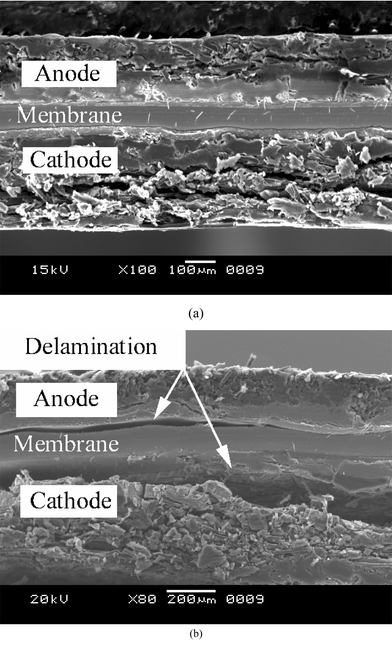 | ||
| Fig. 4 SEM images of MEA in cross-section: (a) before the 75 h life test; (b) after the 75 h life test. | ||
The stability of the electrocatalysts plays an important role on the long-term operation of acid-type fuel cell. In the Phosphoric Acid Fuel Cell (PAFC), the loss of activity in Pt/C due to the agglomeration of the platinum particles is considered to be a major cause of the decay in cell performance.12 The working environment of PEMFC is different from that of PAFC. Relative to the strong adsorption of the phosphoric anions, the anions of the perfluorinated sulfonic acid polymer are only weakly adsorbed on Pt. Furthermore, the temperature of the operation of PEMFC is lower than 100°C, while PAFCs usually operate at ∼200°C. Hence, a better stability of the electrocatalysts in the PEMFC environment is expected. Nevertheless, the surface area of the catalysts in the anode and cathode were reduced and considerable growth of the Pt particles occurred over thousands of hours of life test in PEMFC, which had a significant effect on the cell performance.13,14 For a DMFC, this problem may be become more complex because of the existence of redundant methanol, water and perfluorinated sulfonic acid polymer in the electrodes. TEM analysis was carried out on fresh and used electrocatalysts to investigate the morphological changes of the electrocatalysts after the life test. Fig. 5 presents the TEM images of electrocatalysts in the cathode and anode before and after the life test and corresponding histograms are shown in Fig. 6. The results of Pt/C and PtRu/C before and after the life test show that: (i) The distribution of particle sizes is quite broad after the life test, both for Pt and PtRu. The shape of the histogram of PtRu/C after the test shows a tail toward large-particle sizes. (ii) The average particle size of platinum in the cathode after the test is 4.0 nm, which is slightly different from the average particle size of the as-received Pt/C electrocatalysts. (iii) The agglomeration of PtRu particles in the anode after the test is more severe than in the cathode. Obvious coalescence of metal particles can be seen in Fig. 5(d). The average particle size of PtRu after the test is 7.1 nm and some particles grow up to 15 nm spheres. Rapid growth of platinum particles occurred in the presence of a liquid environment because the sintering process may be enhanced in the presence of liquids by lowering the activation energy of particle growth.13 Wilson et al. also observed a similar effect of hydration level on ionomer-impregnated gas-diffusion electrodes.14 So in PEMFC and PAFC, the ripening is more significant in the cathode than in the anode. However, this conclusion may not be applied to DMFCs, as shown in the results presented in Fig. 5 and 6. Accordingly, methanol may be more aggressive towards electrocatalysts than water.
 | ||
| Fig. 5 TEM images of electrocatalysts: (a) as-received 20% Pt/C; (b) 20% Pt/C after the 75 h life test; (c) as-received 30% PtRu/C (d) 30% PtRu/C after the 75 h life test. | ||
 | ||
| Fig. 6 Histograms of particle size distributions of electrocatalysts: (a) as-received 20% Pt/C; (b) 20% Pt/C after the 75 h life test; (c) as-received 30% PtRu/C (d) 30% PtRu/C after the 75 h life test. | ||
Interestingly, some nano-rods can be observed, which may be formed in the agglomeration process of the noble metal(s). This suggests the growth mechanism of the PtRu particles in the anode of the DMFC might be crystalline migration.13 In our DMFC, the electrocatalysts in the anode are in a more rigorous environment containing methanol, water and acidic perfluorosulfonate ionomer. This may cause more severe agglomeration of catalysts than that in PEMFC. Careful water management can prevent the electrocatalysts in the cathode of PEMFC of being exposed to an excessive amount of water so as to avoid noble metal agglomeration.14 However, as the use of liquid feedstock cannot be avoided in liquid-DMFCs, highly stable anodic electrocatalysts thus have to be developed in which the metal nanoparticles are strongly anchored to the support. PtRu/C catalysts with strong metal support interaction (SMSI) have been achieved on an inert support and the resulting electrocatalysts showed high stability in a preliminary experiment. Longer life tests of such catalysts are under way.
Conclusions
30% of the original maximum power density of a DMFC was lost after a 75 h life test in which the MEA was prepared by a conventional method. The high frequency resistance increases with the test time. This might be attributed to the electrodes cracking from the membrane due to the different degrees of swelling of the electrode and membrane as shown in the SEM images of the used MEA in cross-section. The agglomeration of electrocatalysts in the anode is more severe than in the cathode according to TEM images. This indicates that methanol might be more aggressive towards electrocatalysts than water. The most likely reason for degradation of performance is the delamination of the conventional MEA and the agglomeration of the electrocatalysts.Acknowledgements
The Innovation Foundation of Dalian Institute of Chemical Physics, Chinese Academy of Science, financially supported this work. The authors would also like to thank Dr Bing Zhou from Headwaters Nanokinetix Corp. for helpful discussions.References
- B. McNicol, D. Rand and K. Williams, J. Power Sources, 1999, 83, 15 CrossRef CAS.
- A. S. Arico, S. Srinivasan and V. Antonucci, Fuel Cells, 2001, 1, 1.
- M. P. Hogarth and T. R. Ralph, Platinum Met. Rev., 2002, 46, 146 Search PubMed.
- X. M. Ren, P. Zelenay, J. Davey and S. Gottesfeld, J. Power Sources, 2000, 86, 111 CrossRef CAS.
- S. C. Thomas, X. M. Ren, S. Gottesfeld and P. Zelenay, Electrochim. Acta, 2002, 47, 3741 CrossRef CAS.
- A. K. Shukla, C. L. Jackson, K. Scott and R. K. Raman, Electrochim. Acta, 2002, 47, 3401 CrossRef CAS.
- J. Han and E. S. Park, J. Power Sources, 2002, 112, 477 CrossRef CAS.
- M. S. Wilson, F. H. Garzon, K. E. Sickafus and S. Gottesfeld, J. Electrochem. Soc., 1993, 140, 2872 CAS.
- J. T Mueller and P. M Urban, J. Power Sources, 1998, 75, 139 CrossRef.
- N. Wagner, J. Appl. Electrochem., 2002, 32, 859 CrossRef CAS.
- K. Andrew, US Pat., 5, 992,008, 1999 Search PubMed.
- E. Antolini, J. Mater. Sci., 2003, 38, 2995 CrossRef CAS.
- M. S. Wilson, J. A. Valerio and S. Gottesfeld, Electrochim. Acta, 1995, 40, 355 CrossRef CAS.
- J. St-Pierre, D. P. Wilkinson, S. Knights and M. Bos, J. New Mater. Electrochem. Syst., 2000, 3, 99 Search PubMed.
| This journal is © the Owner Societies 2004 |