Chemical and physical processes for integrated temperature control in microfluidic devices
Rosanne M.
Guijt†
ab,
Arash
Dodge†
a,
Gijs W. K.
van Dedem
b,
Nico F.
de Rooij
a and
Elisabeth
Verpoorte
*a
aSAMLAB, Institute of Microtechnology, University of Neuchâtel, Switzerland
bKluyver Institute for Biotechnology, Delft University of Technology, the Netherlands
First published on 16th December 2002
Abstract
Microfluidic devices are a promising new tool for studying and optimizing (bio)chemical reactions and analyses. Many (bio)chemical reactions require accurate temperature control, such as for example thermocycling for PCR. Here, a new integrated temperature control system for microfluidic devices is presented, using chemical and physical processes to locally regulate temperature. In demonstration experiments, the evaporation of acetone was used as an endothermic process to cool a microchannel. Additionally, heating of a microchannel was achieved by dissolution of concentrated sulfuric acid in water as an exothermic process. Localization of the contact area of two flows in a microfluidic channel allows control of the position and the magnitude of the thermal effect.
Introduction
Since the introduction of the miniaturized total chemical analysis system (μTAS) concept in 1990,1 the development of so-called ‘lab-on-chip’ devices has been an area of exponential growth. Miniaturization of chemical systems allows faster chemical reactions, due to reduced diffusion-driven transport times, and faster and more efficient separations. Working on a small scale reduces the risks involved in manipulation of explosive and unstable mixtures required for chemical reactions. Additionally, working with a microchip format dramatically reduces the consumption of sample and reagents, and allows the performance of multiple analyses in parallel, thereby lowering the price per analysis. Large surface-to-volume ratios also allow better thermal control. Heating and cooling of small liquid volumes can be accomplished in much shorter periods of time. The small thermal mass of the chips themselves also contributes to increased heating and cooling rates.Enhanced heat transfer introduces the potential for improved control of chemical process conditions in microreactors. Certainly, the excessive heat build-up which often leads to runaway reactions in conventional reactors can be avoided.2 Precise temperature control is also required in certain (bio)chemical reactions, such as DNA amplification using the polymerase chain reaction (PCR),3 and the investigation of reaction kinetics. PCR is a biochemical reaction requiring rapid and precise thermocycling of reagents at three different temperatures between 50 °C and 100 °C. The potential of faster temperature ramping and more precise temperature control has been the impetus for the integration of PCR into microfabricated devices. The earliest examples of this development were presented by Northrup et al. in 19934 and Wilding et al. in 1994.5 More recently, efforts in a number of groups have resulted in several examples of PCR on chip. In the devices described in references 5–9 external thermal control was used, whereas in references 2, 4 and 10 heating elements were incorporated in the device through integration of resistive layers heated by the Joule effect. Control of exothermic reactions in micromachined chemical reactors has also been presented using integrated heaters in microreaction chambers.2
Until now, cooling of microfluidic devices has only been done with external components or by convection. It has been achieved by clamping5 or gluing the microfluidic device to an external Peltier element,9 or by contacting the microdevice with a copper block, passively cooled by contact with cooling fins.6 The convection technique primarily consists of using the heat exchange between the device and ambient air, an effect which may be enhanced by blowing compressed air or nitrogen gas over the microdevice.7,8,10 Only two integrated cooling techniques have been presented, neither of them for microfluidic devices but for micro-electronics. In one case, an integrated cooling system utilizing a microchannel in a printed circuit board (PCB) was described. Either water or methoxynonafluorobutane were used as coolants and pumped through the microchannel, removing heat from the electronics.11 The heat was dissipated in a heat exchanger, positioned elsewhere on the PCB. A comparable system using microfluidics in combination with a heat exchanger for cooling electronics has been described elsewhere.12 In the second case, integrated cooling of microelectronic devices took the form of the ‘fridge-on-a-chip’.13 Here, microPeltier elements were integrated during the microfabrication process on the back of microelectronic devices.
Most of the cooling systems described above require external and often bulky components, thereby limiting the possibilities of integration in a microfluidic device. Even the microfluidic cooling system integrated on the PCB11 required a heat exchanger elsewhere on the device, complicating the microfabrication process and increasing the footprint of the device and fabrication costs. Similarly, heating small volumes on-chip involves the use of external elements, or additional fabrication steps for integration of heating elements. The approach for chip-based temperature modification presented here is quite different, as it is based on the exploitation of endothermic or exothermic processes in microchannels to respectively cool or heat solutions in an adjacent microchannel. The temperature control channels (TCCs) are directly integrated in the chip at the same time that the microfluidics are fabricated by simple single-level microfabrication. Localization of the cooling or heating effect is controlled by positioning the endothermic or exothermic processes at the reactant flow interface.
Experimental
Under the usual operating conditions for microfluidic devices, fluid flows are laminar. That is, the velocity at any one point in a channel is predictable and unchanging, and streamlines are well defined. When two fluids coming from two different reactant channels (RC) are merged together into a single microfluidic channel (Fig. 1A), they generally follow laminar streamlines and flow side-by-side. The stream from RC2 flows along the side of the TCC closest to the central channel (Fig. 1B). The relative widths of the fluid flows are determined by the flow rate ratio. At the interface, chemical or physical processes can occur. In the example presented here, two-component processes were used. For cooling, the evaporation of acetone was used as an endothermic process. In the TCC, air flowed from RC1 alongside acetone (Laporte Electronics, UK) from RC2, cooling down the central channel. For heating, the violently exothermic dissolution of 97% H2SO4 (Merck, Switzerland) in water was used, with water in RC1 and H2SO4 in RC2. | ||
| Fig. 1 (A) Two RCs merging into a TCC. (B) Layout of the device used for demonstration experiments (not to scale). Distance between the central channel and CC: 30 μm. Channel depths are 19 μm, TCC width is 108 μm and RC widths are 54 μm. | ||
A microfluidic structure (layout in Fig. 1B) was etched into a glass substrate using conventional photolithographic techniques and wet chemical etching in 50% HF.14 For cooling experiments, a closed microchannel system was formed by reversible bonding of the glass substrate with poly(dimethylsiloxane) (PDMS). For heating experiments, thermally bonded glass–glass devices were used. Vacuum at the end of the TCC was used to draw in the components from RC1 and RC2 into the TCC, initializing the endothermic or exothermic processes, and thus inducing the thermal effect. TCCs were integrated along both sides of the central channel to obtain a symmetrical temperature effect, as shown in Fig. 1B.
To estimate the temperature changes achieved in the central channel, two fluorescence-based calibration methods were used. The fluorescence of rhodamine B strongly depends on the temperature, with fluorescence decreasing as a function of increasing temperature.15–18 A calibration plot of fluorescence intensity as a function of temperature was made in a glass device by filling the central channel with a 1 μM rhodamine B (Sigma, Switzerland) solution in water and using an indium tin oxide layer (ITO) as an integrated heater. Temperature was measured with a Pt-100 sensor glued to the ITO layer with thermal epoxy. Images were taken with an inverted fluorescence microscope and a digital camera. Pixel processing of the images enabled generation of quantitative data, allowing calculation of the effect of temperature on fluorescence intensity. This calibration curve was obtained by measuring fluorescence as a function of the temperature of the ITO layer, which was not the same as inside the microchannel containing the dye. Therefore, a second method was used to calibrate the internal temperature as a function of the externally applied temperature, using molecular beacons as temperature-sensing compounds. Molecular beacons are oligonucleotide probes having a hairpin-loop-shaped molecular structure with an internally quenched fluorophore.19–21 It is possible to open the hairpin double-stranded structure of the beacon, by either binding the single-stranded loop structure to a complementary strand or by melting the double strand. In both cases the hairpin is opened, spatially separating the quencher from the fluorophore, thereby allowing fluorescence upon excitation. The melting temperature (Tm) of the double strand depends on its length and composition, and is very specific. Molecular beacons with different Tm's are available. Fluorescence measurements with a tetramethylrhodamine–dabcyl beacon (TAMRA–dabcyl, purchased from Eurogentec, Belgium) with a Tm at 54.6 °C and a Cy5-Black Hole Quencher beacon (Cy5-BHQ3, purchased from Biosearch Tech, USA) with a Tm at 71.5 °C were used to correct the rhodamine B calibration curve. Beacon solutions (5 μM) were prepared in a buffer containing 100 mM Tris/HCl (Fluka, Switzerland) and 1 mM MgCl2 (Merck, Switzerland) at pH 8.0. Tm’s were obtained by measuring beacon fluorescence intensity as a function of temperature in a conventional fluorimeter. The resulting curves are sigmoidal in shape, with the Tm being defined by the inflexion point of the fitted curve. The corrected rhodamine B fluorescence–temperature curve is presented in Fig. 2.
 | ||
| Fig. 2 Fluorescence intensity of 1 μM rhodamine B as a function of temperature. Fluorescence signal was measured as a function of temperature by heating a rhodamine B solution in a glass chip, using a transparent integrated ITO layer as heater and a Pt-100 sensor as feedback. The signal was collected with a CCD camera mounted on a fluorescence microscope, and pixel-processed to obtain quantitative data. | ||
Results and discussion
During cooling experiments, RC2 was filled with acetone, RC1 with air, and vacuum was applied to the waste reservoir at the end of the TCC. The central channel was filled with a solution of 1 μM rhodamine B in water. In Fig. 3, images of the central channel show the fluorescence increase as a result of the temperature decrease obtained by the evaporation of acetone in the TCCs. | ||
| Fig. 3 Chip design with fluorescence microscope images taken (A) before and (B) during cooling of a 1 μM rhodamine B solution. Air-to-acetone flow rate ratio was 0.3∶1. Note the difference in fluorescence in the central channel. Signal increases as temperature decreases. | ||
The extent to which liquid is cooled in the microchannel depends on the evaporation rate of acetone, and can be influenced by varying relative flow rates from RC1 and RC2. These latter parameters can be controlled by varying the flow resistance of the channels involved. Flow resistance depends on channel cross-section and length as well as fluid viscosity. If a certain pressure P is applied to a channel i, the flow Qi induced through the channel is given by:
| Qi = 2AiDi2Pi/CiηiLi | (1) |
In our device, the vacuum applied to the waste reservoir simultaneously creates the same negative pressure at the ends of RC1 and RC2. They also both have the same cross-sectional area so that, using eqn. 1, the flow rate ratio between RC1 and RC2 becomes:
| Q1/Q2 = η2L2/η1L1 | (2) |
Two different structures were tested to verify the difference in the cooling effect induced by varying the air-to-acetone flow rate ratio, as presented in Table 1. Using eqn. 2, we obtain 0.3∶1 and 7∶1 air-to-acetone flow rate ratios. The temperatures in the central channel are approximated at 5 °C and −3 °C, respectively, using the corrected rhodamine calibration curve, demonstrating the influence of the flow ratio on the cooling effect.
Cooling in glass–glass devices was less efficient than in the glass–PDMS hybrids. We think this is because acetone vapor also escapes through the gas-permeable PDMS, thereby driving the acetone evaporation process more strongly and augmenting the cooling effect. This implies that a larger air–acetone contact surface would be required for efficient cooling in a fully glass device. Variation of the PDMS lid thickness could also change the rate of acetone evaporation and therefore affect the cooling effect, but this has not been tested.
Heating experiments were performed in glass–glass devices, with a layout and operating procedure identical to the devices used for the cooling experiments (layout in Fig. 1B). Concentrated H2SO4 from RC2 and water from RC1 come together in the TCC, where the exothermic dissolution process takes place. Devices identical to the ones used for the cooling experiments were used to investigate the effect of flow ratio on heating. Since the viscosities of the fluids used in this case are different, the flow rate ratios change as indicated in Table 1. For the 0.4∶1 water-to-H2SO4 flow rate ratio, a temperature of 76 °C could be estimated in the rhodamine-containing channel, whereas for the 11∶1 ratio, heating up to 36 °C was estimated. These results are summarized in Table 1. In both heating and cooling experiments, temperature ramps of about 1 °C s−1 were obtained. This was estimated by timing the delay between initiation of cooling or heating and establishment of equilibrium in video sequences. Experiments were not performed under conditions of controlled ambient temperature.
For additional heating experiments, the central channel was filled with the TAMRA–dabcyl molecular beacon solution, with a Tm at 54.6 °C. In analogy with the experiments described above, water was present in RC1, and the exothermic process was initiated by pipetting 97% H2SO4 into RC2 while vacuum was applied to the waste reservoir. Images taken before (A) and after (B) initiating the heating effect are given in Fig. 4. The fluorescence increase observed in Fig. 4B relative to Fig. 4A is caused by opening of the molecular beacon, demonstrating heating above 54.6 °C. When the exothermic process was stopped by removal of the H2SO4 from RC2, the fluorescence intensity dropped back to the original level. The observation of this single biochemical event demonstrates that it is possible to control and influence chemistries inside a microchannel with this device.
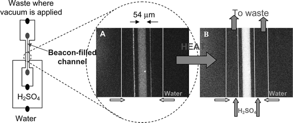 | ||
| Fig. 4 Chip design with fluorescence microscope images taken (A) before and (B) during heating of a TAMRA-beacon solution. The water-to-H2SO4 flow rate ratio was 0.4∶1. Note the difference in fluorescence in the central channel. Signal increases above the melting temperature of the beacon (54.6 °C). | ||
Conclusions
A new, integrated method for spatially localized cooling and heating in microfluidic devices was presented using endothermic and exothermic processes, respectively. The thermal effect was initiated by mixing two components by application of a vacuum. The extent of the thermal effect can be controlled by either the flow ratio of the two components, or by selection of the components based on their chemical or physical properties. It is also dependent on the external ambient temperature.Integration of the temperature control system in microfluidic devices is simple, and does not require additional microfabrication steps. Since the chemical or physical processes take place in a microchannel, integration of a temperature control system does not dramatically increase the footprint of a device. Multiple cooling and heating systems could be integrated along a single reaction channel, allowing thermocycling of compounds migrating or being pumped through this channel. The small feature size of the cooling system also allows multiple temperature control units on a microdevice where multiple endothermic and exothermic processes occur in parallel. Additionally, the driving force of the system is vacuum, resulting in low-power consumption during cooling or heating. The cooling system described might also be attractive for cooling of microelectronic devices.
Acknowledgements
The authors would like to thank G. Turcatti (Manteia, Nyon, Switzerland) for measurement of the molecular beacon melting curves in a conventional system.R.M.G. was financially supported by the Dutch Technology Foundation STW, Applied Science Division of NWO and the technology program of the Ministry of Economic Affairs, in the framework of the BIOMAS project (DST 66.5341). A.D. acknowledges funding by the “Nanocontainer” project No 5493.2 TN, administered by the Swiss Commission of Technology and Innovation.
References
- A. Manz, N. Graber and H. M. Widmer, Sens. Actuators B, 1990, 1, 244–248 CrossRef.
- K. F. Jensen, I.-M. Hsing, R. Srinivasan and M. A. Schmidt, in Proceedings of the First International Conference on Microreaction Technology (Frankfurt am Main, Germany, February 23–25, 1997), ed. W. Ehrfeld, Springer-Verlag, Berlin, Heidelberg, 1998, pp. 2–9 Search PubMed.
- K. Mullis, F. Faloona, S. Scharf, R. Saiki, G. Horn and H. Erlich, Cold Spring Harbor Symp. Quant. Biol., 1986, 51, 263–273 Search PubMed.
- M. A. Northrup, M. T. Ching, R. White and R. T. Watson, Technical Digest of Transducers′93: 7th International Conference on Solid State Sensors and Actuators, Yokohama, Japan, 1993, pp. 924–927 Search PubMed.
- P. Wilding, M. A. Shoffner and L. J. Kricka, Clin. Chem., 1994, 40, 1815–1818 CAS.
- M. U. Kopp, A. J. de Mello and A. Manz, Science, 1998, 280, 1046–1048 CrossRef CAS.
- R. P. Oda, M. A. Strausbauch, A. F. R. Huhmer, N. Borson, S. R. Jurrens, J. Craighead, P. J. Wettstein, B. Eckloff, B. Kline and J. P. Landers, Anal. Chem., 1998, 4361–4368 CrossRef CAS.
- E. T. Lagally, P. C. Simpson and R. A. Mathies, Sens. Actuators B, 2000, 63, 138–146 CrossRef.
- J. Khandurina, . E. McKnight, S. C. Jacobson, L. C. Waters, R. S. Foote and J. M. Ramsey, Anal. Chem., 2000, 72, 2995–3000 CrossRef CAS.
- R. Srinivasan, I. M. Hsing, P. E. Berger, K. F. Jensen, S. L. Firebaugh, M. A. Schmidt, M. P. Harold, J. J. Lerou and J. F. Ryley, Am. Inst. Chem. Eng. J., 1997, 43, 3059–3069 Search PubMed.
- J. Schütze, H. Ilgen and W. R. Fahrner, IEEE Trans. Ind. Electron., 2001, 48, 281–285 CrossRef.
- S. D. O′Connor and E. Dantsker, in US Pat. Appl. 20020039280, Filed September 28, 2001, Published April 4, 2002.
- X. Fan, G. Zeng, C. LaBounty, J. E. Bowers, E. Croke, C. C. Ahn, S. Huxtable, A. Majumdar and A. Shakouri, Appl. Phys. Lett., 2001, 78, 1580–1582 CrossRef CAS.
- A. Dodge, K. Fluri, E. Verpoorte and N. F. de Rooij, Anal. Chem., 2001, 73, 3400–3409 CrossRef CAS.
- J. A. Ferguson and W.-H. Mau, Aust. J. Chem., 1973, 26, 1617–1624 CAS.
- J. Sakakibara, K. Hishida and M. Maeda, Exp. Fluids, 1993, 16, 82–96 CrossRef.
- M. N. Slyadnev, Y. Tanaka, M. Tokeshi and T. Kitamori, Anal. Chem., 2001, 73, 4037–4044 CrossRef CAS.
- D. Ross, M. Gaitan and L. E. Locascio, Anal. Chem., 2001, 73, 4117–4132 CrossRef CAS.
- S. Tyagi and F. R. Kramer, Nat. Biotechnol., 1996, 14, 303–308 CrossRef CAS.
- S. Tyagi, D. P. Bratu and F. R. Kramer, Nat. Biotechnol., 1998, 16, 49–53 CrossRef CAS.
- G. Bonnet, O. Krichevsky and A. Libchaber, Proc. Natl. Acad. Sci. USA, 1998, 95, 8602–8606 CrossRef CAS.
- CRC Handbook of Chemistry and Physics, The Chemical Rubber Publishing Company, Cleveland, Ohio, 1960, pp. 2196–2202 Search PubMed.
Footnote |
| † Both authors contributed equally to this research. |
| This journal is © The Royal Society of Chemistry 2003 |