DOI:
10.1039/B209717F
(Invited Article)
Phys. Chem. Chem. Phys., 2003,
5, 1-11
Dynamical properties of X-ray Raman scattering
Received
7th October 2002
, Accepted 15th November 2002
First published on 28th November 2002
Abstract
This paper reviews theory for resonant X-ray scattering, emphasizing the dynamical aspects related to the nuclear motion during the scattering process. Various features of the theory are illustrated by simulations on small molecules in the gaseous phase. After the introduction defining the X-ray Raman scattering process, we briefly describe some central concepts of its theory: the Raman law, the time hierarchy of X-ray scattering and the generalized Kramers–Heisenberg relation. We then go into some detail of various theoretical aspects of the process: transition moments and light polarization, time-dependent formulation and wave packets. We review two aspects of recent experimental focus: Doppler effects and generalized Franck–Condon factors. In the last part of the paper we discuss X-ray Raman scattering of dissociative core excited states, and the intriguing concept of a duration time for the scattering. We address dissociative resonant photoemission from first principles, with particular emphasis on the conditions for observing so-called “atomic peaks” and “atomic holes”. The atomic holes are the results of continuum–continuum interference effects between the atomic and molecular channels which may act destructively under certain conditions. We demonstrate that the resonant contribution and the evolution of the atomic peaks can be subject to strong dynamical suppression caused by nuclear motion. In general, the molecular geometry dependence of the electronic transition moments can change the scattering cross section quite dramatically. This is exemplified here by an unusual spectral flattening for the B state of N2, and by a breakdown of the spectator versus participator classification in a part of the non-radiative resonant photoemission spectrum of HF. The notion of a duration time in resonant X-ray scattering is put forward as a powerful concept for predicting and understanding qualitative aspects of many of the effects or processes treated in this paper. The role of the pulse shape for short pulse X-ray excitation is also discussed.
I. Introduction
Resonant X-ray Raman scattering (RXS) is a spectroscopic technique for studies of electronic structure of atoms, molecules and solid matter.1–8 In an RXS experiment, the sample is irradiated with X-rays that are able to excite electrons occupying tightly-bound core orbitals. The core-excited states created in this way are short-lived, the lifetime is often of the order of few femtoseconds, and decay to one of many possible final states which usually are valence excited states. From the electronic structure point of view, there exist two distinct decay channels: radiative, when an X-ray photon is emitted, or non-radiative, when the extra energy is released through Auger electron emission. The theory of X-ray Raman scattering has been much boosted by the rapid development of high intensity synchrotron light sources. Many new and fundamental features have been revealed and interpreted in the spectra, and some of them explained. We describe here theory of X-ray Raman scattering on free molecules with relevance to current experiments at synchrotron radiation facilities.
The irradiated target interacts with the radiation field through the dipole moment D of the molecule as given by the absorption cross section σ![[thin space (1/6-em)]](https://www.rsc.org/images/entities/char_2009.gif) ∼|〈Φc|D·e|Φ0〉|2, where e is the X-ray photon polarization vector. The X-ray photons have sufficient energy to excite the core electrons to an unoccupied orbital or even to ionize the molecule. The RXS process occurs when the photon energy ω is chosen below the core electron ionization threshold. The created core-excited state subsequently decays emitting excessive energy with a photon or an Auger electron of energy E that can be measured by an energy-dispersive spectrometer.
∼|〈Φc|D·e|Φ0〉|2, where e is the X-ray photon polarization vector. The X-ray photons have sufficient energy to excite the core electrons to an unoccupied orbital or even to ionize the molecule. The RXS process occurs when the photon energy ω is chosen below the core electron ionization threshold. The created core-excited state subsequently decays emitting excessive energy with a photon or an Auger electron of energy E that can be measured by an energy-dispersive spectrometer.
The excitation and decay processes happen so quickly relative to the nuclear vibrational speed that one can say that the electronic wave functions (and associated potentials surfaces) switch suddenly without any change of the nuclear wave function. The Franck–Condon
(FC)
principle states that an electronic transition takes place so rapidly that a vibrating molecule does not change its geometry appreciably during the transition. Due to this circumstance the probability amplitude to find a molecule in a certain final vibrational state is given by the projection of the initial vibrational state wave function on the final vibrational state wave function (FC amplitude). This overlap between nuclear states appears in this or a similar form in many places of the RXS theory.
The interplay between the vibrational motion and decay process opens a new field of investigations, which also is the subject of this paper. One can observe that for fast decay processes, the wave packet on the core-excited potential surface will not have time to evolve, and the scattering spectrum will be similar to the one of the absorption directly to the final state as seen on Fig. 1. The other limiting case is when the core hole state is long-lived and the molecule dissociates before the decay (Fig. 1). The decay process will be analogous to the one occurring in single atoms and the spectrum will consist of narrow atomic peaks at positions determined by the energy differences between atomic energy levels. The intermediate case when the core-hole state Φc has a lifetime Γ−1 of the same order as the dissociation time leads to a cross section simultaneously having a molecular background as well as atomic peaks. These fast and slow decay channels will interfere giving rise to rich spectra providing much information about the scattering process.
 |
| | Fig. 1 The general principle of Raman scattering. The molecule is excited from the initial state |0〉 to the intermediate state |c〉 and decays after some time to the final state |f〉. When the scattering duration is very short, the initial wave packet appears on the final surface unchanged. | |
II. Raman law
Let us start from the simplified Kramers–Heisenberg (KH) formula describing the X-ray Raman scattering cross section in order to find out basic properties of the cross section and its dependence on the photon frequency ω. We focus on the resonant contribution to the cross section only and neglect any geometry dependence of the electronic transition moments. We obtain the following expression9–11 for the cross section σ(ω,E) as a function of ω and the emitted particle energy E| |  | (1) |
Here, |0〉, |c〉 and |f〉 are vibrational wave functions of ground, core-excited and final states, respectively, and E0, Ec and Ef are associated energies; V and Q are the electronic transition matrix elements of core excitation and decay, respectively; Δ(ω,Γ)=Γ/π(ω2+Γ2). The cross section is expressed through the sum over all final states |f〉 with the lifetime Γ−1f. Since the numerator is energy independent, the magnitude of the cross section as function of photon energy ω is determined by the denominator. This denominator blows up for a photon energy equal to one of the resonance frequencies ω=Ec−E0. An interesting experiment that can be performed is to investigate the cross section evolution on the detuning from the resonance.
Also, we learn from the Δ–function in eqn. (1) that the dependence of the final particle (photon or Auger electron) energy, E, on the excitation energy is determined by
which is the so-called Raman law.
Fig. 2 shows the RXS cross section computed for the HCl molecule; it can be clearly seen that the molecular part behaves according to the Raman law with detuning while the position of the atomic peak remains constant.
 |
| | Fig. 2 The RXS cross section σ(ω,E) for 2p core-excited HCl molecule and lowest 2Σ+ final state. The molecular part corresponding to the fast decay moves according to the Raman law while the atomic peak remains at the same position. Reproduced from Sałek et al.2
(Copyright American Physical Society). | |
III. Time hierarchy of X-ray scattering
Different physical processes contribute to the formation of X-ray spectra. Each of them has its own characteristic time. Clearly, the roles of different processes in the formation of the X-ray profiles depend strongly on the corresponding time scale. We will give a brief analysis of some of these characteristic time scales.
A. Scattering duration
A specific feature of RXS is illustrated by the KH formula (1) in the case of large detuning Ω=ω−(Ec−E0), or large lifetime broadening,  , where ωvib is the vibrational frequency. The detuning is an important parameter which influences different optical processes,13,14 in particular, Raman scattering. The closure condition
| |  | (3) |
results immediately in| | 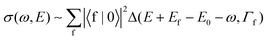 | (4) |
This equation has an interesting interpretation: One finds in the case where the period of vibrations τvib=2π/ωvib is shorter than (Γ2+Ω2)−1/2 that the RXS process is “fast” and corresponds to a sudden transition to the final state |f〉 since the nuclear wave packet has no time to evolve on the core-excited potential surface. This allows us to interpret| |  | (5) |
as the RXS duration time. Also, we have used the completeness of the intermediate vibrational states, eqn. (3), in order to derive the limiting case in eqn. (4). This means that the RXS duration time is essentially a quantum notion and closely related with the state interference.15
It is appropriate to give a qualitative discussion of the RXS duration time for large detunings which results in fast oscillations of the scattering amplitude, F(t)∝exp[(iΩ−Γ)t], in the time dependent representation:15F=∫∞0dtF(t). Fig. 3 shows that these fast oscillations with the detuning frequency Ω cancel each other for times
| | | t>T. | (6) |
In fact, only small time intervals (shorter than the RXS duration
T,
eqn. (5)) contribute to the stationary scattering amplitude
F.
 |
| | Fig. 3 Detuning as means of controlling the duration of the scattering process, T. Only short-time contributions from the RXS amplitude, F, prevail because of the destructive interference for large times t. | |
The concept of RXS duration time appears frequently in RXS theory. It is also quite appealing from the experimental point of view by providing means to control the scattering time: While the core-excited state lifetime is a molecular property, the incident photon frequency can be chosen at will. We see that the timing for the scattering process is possible via the frequency detuning of RXS, which acts effectively as a camera shutter analogous to time dependent pump–probe measurements, Fig. 3.
B. Characteristic time of nuclear motion
The other characteristic time apart from the scattering time is the one that characterizes the motion of the wave packet. For a bound state, the vibrational period can be estimated as
For ordinary diatomic molecules, the distance between vibrational levels is of the order 0.1–0.3 eV and the period of the vibrational motion is about 15–20 fs. The character of the decay is different if the scattering time T is shorter than the vibrational time; the core-excited state decays before the molecule manages to perform one entire vibration. The vibrational structure of the core-excited state can then not be seen any more.
The characteristic time τnucl in the case of dissociative core excitation is the dissociation time
which is the time of flight with the speed
v from the equilibrium to the region of dissociation. Again, if the molecule dissociates faster than it decays, the RXS spectrum will look like a spectrum of a core-excited atom. In the opposite limit of fast decay, the spectrum will be more directly photoionization-like.
Fig. 4 shows that the spectral shape of RXS depends strongly on the interplay of the RXS duration and characteristic time of the wave packet evolution τnucl. The RXS duration gives us a tool of an active operation by the physical processes with different time scales which influence the RXS profile. When the duration T is small (large Ω) the nuclear wave packet has no time to evolve on the core-excited potential surface and copies the narrow ground state nuclear wave function (see Fig. 4c).
 |
| | Fig. 4 The space distribution of |ΨT(∞)|
versus the RXS duration (detuning) for the bound core-excited state 1Πu of N2. The contribution of the region outside of the ground state vibrational wave function is suppressed when Ω is large. Γ=0.065 eV. The RXS duration times are: |T|≃5.6 fs, 0.73 fs, and 0.35 fs for the excitation frequencies ω=401 eV (at resonance), 402 eV, and 403 eV, respectively. Reproduced from Gel'mukhanov et al.15
(Copyright American Physical Society). | |
Generalized Kramers–Heisenberg description
It is well established that both radiative and nonradiative RXS can be described on the same footing making use of the generalized KH formula. The extended —including direct photoionization channel— KH formula describing the scattering cross section connected with emission of a particle of energy E is2| | 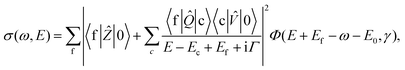 | (7) |
where the emitted particle can be either a photon in the case of radiative decay, or an Auger electron in the case of non-radiative decay, and where Φ(ω,γ) is the spectral function of the incident radiation with the spectral width γ
(≫Γf). The excitation operator ![[V with combining circumflex]](https://www.rsc.org/images/entities/i_char_0056_0302.gif) is an ordinary dipole moment operator between the ground electronic and the core-excited states. The decay operator
is an ordinary dipole moment operator between the ground electronic and the core-excited states. The decay operator ![[Q with combining circumflex]](https://www.rsc.org/images/entities/i_char_0051_0302.gif) is a dipole moment operator between core-excited and final states in the case of radiative decay, or a Coulomb operator in the case of non-radiative scattering. We include also in the formalism the direct photo-ionization term associated with the dipole transition operator Ẑ between ground and final electronic states (Fig. 5).
is a dipole moment operator between core-excited and final states in the case of radiative decay, or a Coulomb operator in the case of non-radiative scattering. We include also in the formalism the direct photo-ionization term associated with the dipole transition operator Ẑ between ground and final electronic states (Fig. 5).
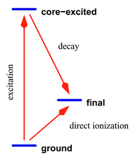 |
| | Fig. 5 Simplified scheme of RXS. The electronic energy levels are assumed to be constant under scattering. Two channels are allowed: either Raman scattering with an emission of an Auger electron, or direct photoionization. Because the final states are identical these two channels will interfere. | |
The transition operators can be factored out when one is interested in the spectral shape of the cross section only–assuming that these operators do not strongly depend on the molecular geometry. The molecular geometry dependence of the excitation operators Ẑ and is practically always negligible because with the right-hand state |0〉 being the ground state the wave packet is well localized in space. On the other hand, the core-excited |c〉 and final |f〉 wave packets are often delocalized and there exist some cases where the geometry dependence of the decay operator is the key point in the explanation of the RXS spectrum: see for example ref. 16. The lifetime Γ−1 of the core-excited state determines not only the width of the absorption band, but being connected to the core-excited state total decay rate, it changes also the spectral shape of the scattering spectra.
V. Time-dependent RXS theory. Wave packet methods
The spectral shape of the cross section, eqn. (7), can readily be investigated by time-independent formulations. In fact for Raman scattering such time-dependent formulations have been proposed, and applied, for some time.17–19 These approaches, being computationally very efficient for bound states, become numerically expensive for dissociative nuclear states. Time-dependent wave packet methods pioneered by Heller19 are natural for a time-dependent process like X-ray scattering; with the relation between the lifetime and the speed of vibrational or dissociative motion being an integral part of the theory. Wave packet methods simulating the nuclear motion of the molecule induced in the scattering process are thus very helpful to understand the physics of the formation of spectral shape of the cross section.
In the wave packet language, the scattering process can be explained as follows: The internal energy of the molecule gained by the absorption of the incident X-ray photon is initially contained in the electronic degrees of freedom but the excited electronic structure induces a nuclear motion with the energy being transferred to vibrational or dissociative motion of the nuclei. Wave packet methods give therefore the most natural ways of describing the scattering process.
The KH formula can be rewritten to the time-dependent formalism yielding12,20
| | | σ(ω,E)=∫σ0(ω′,E)Φ(ω−ω′,γ)dω′ | (8) |
| |  | (9) |
| |  | (10) |
where |
Ψ(0)〉 expresses a wave packet integrated over its entire evolution time on the core-excited potential surface and containing the entire non-trivial dependence of the cross section on detuning
| | 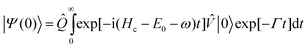 | (11) |
| | |Ψ(τ)〉=exp[−i![[H with combining tilde]](https://www.rsc.org/images/entities/i_char_0048_0303.gif) fτ]|Ψ(0)〉 fτ]|Ψ(0)〉 | (12) |
Here we included the final state lifetime broadening in the Hamiltonian of the final state:
f=
Hf−
i
Γf.
The correlation function in eqn. (10) has three major terms. The first one expresses the resonant cross section, the second one the photoionization channel, and the third one is the interference term between the resonant and direct channels. Eqn. (10) is different for a homonuclear molecule because the wave functions of emitted electrons from two atoms differ by a phase factor. The correlation function then becomes
| | | σ0(τ)=σ(1)0(τ)+σ(2)0(τ)+σ(12)0(τ) | (13) |
| | | σ(j)0(τ)=〈Ψ(j)(0)|Ψ(j)(τ)〉 j=1,2 | (14) |
| | | σ(12)0(τ)=Ψ(1)(0)|Ψ(2)(τ)〉+Ψ(2)(0)|Ψ(1)(τ)〉 | (15) |
where the difference between |
Ψ(1)(
τ)〉 and |
Ψ(2)(
τ)〉 is expressed by the
operator:
| | | 1=0exp[−iαk·R] 2=0exp[+iαk·R] | (16) |
and where the direct and corresponding interference terms are neglected for simplicity. Here,
k is the momentum of the emitted Auger electron,
α=
mB/(
mA+
mB) is the mass ratio coefficient, equal to 1/2 for a homonuclear molecule, and
R is the radius vector. The three terms in
eqn. (13) correspond to the scattering cross section on the first atom, on the second atom, and the interference between them, respectively.
The name “wave packet method” embraces a broad range of approaches including also various semi-classical methods. We treat here strictly only quantum methods using a finite difference representation of the wave packet. The finite difference method represents a function by sampling its values usually at equidistant grid points. One can interpret it as an expansion of the wave function in basis functions which are localized on well determined points.
Wave packet techniques possess a strong competitive edge over time-independent approaches because they do not require explicit knowledge of the eigenfunctions. Instead, only the time evolution operator has to be implemented. This property may not be decisive in the case of bound systems but makes a large gain for dissociative states where a continuous energy spectrum is occupied; the time-independent methods would require to include all the relevant eigenfunctions which could be computationally challenging.
VI. Transition moments. Light polarization
As argued earlier the transition moments can usually be factored out from the cross section expressions. We will discuss now the conditions when this approximation can be carried out and what the consequences of the approximation are.
The transition moments corresponding to the Ẑ, and operators are molecular properties that can be deduced from the electronic structure of the investigated molecule. As such, they can evidently change with the molecule geometry. This dependence can often be neglected for excitation transition moments because Ẑ and operate on the ground state wave packet |0〉 which is localized around the equilibrium geometry of the molecule and because the transition moments, being smooth functions of the geometry, are unlikely to change rapidly in such a limited region. The decay transition moment behaves differently; this operator is folded between core-excited and final states that are in principle extended over a much larger range of molecular geometries (particularly in the case of dissociative electronic states) and the geometry dependence of this parameter may have substantial influence on the cross section. A good example of this is given by the B state of the core-excited N2 as plotted on Figs. 6 and 7: The original lifetime vibrational interference (LVI) formula18,21–23 cannot explain the unusual flattening of the spectrum. This effect occurs due to a strong R-dependence of transition moments for this state; the R-dependence can be attributed to an avoided crossing between “dark” and “bright” electronic configurations. Even in the case of weak geometry dependence, a calculation that includes both the resonance and direct photoionization terms requires the values of the transition moments to preserve the correct ratio between the two channels.
 |
| | Fig. 6 Comparison of cross sections obtained for N2 from the strict LVI formula18 and our formalism with R-dependent transition moments included. Reproduced from Sałek et al.16
(Copyright American Physical Society). | |
 |
| | Fig. 7 Experimental spectrum of the B state of N2. Reproduced from Piancastelli et al.24
(Copyright IOP Publishing). | |
The other important quantity is the polarization e of the incident light. It adds an orientation sensitive factor to the transition moment
This equation shows that the incident
photon excites molecules only with a certain orientation
Dco‖
e. Such an oriented ensemble of core-excited molecules gives rise to an anisotropy of the emitted electrons and X-ray
photons even for disordered samples.
25,26
VII. Doppler correction to X-ray scattering
There is another element in the scattering that has to be taken into account: The Auger electron is not emitted from a molecule at rest but from a dissociating one, or one in a vibrational motion – and the molecular center of mass is moving as well. Generally, there are more Doppler-type effects, as classified on Fig. 8, but only the Doppler effect associated with the electron emission in the dissociative motion can be measured with currently available apparatus.
 |
| | Fig. 8 Classification of Doppler effects. Four possible contributions to the Doppler shift are shown. The electron Doppler effect in the dissociative motion is the largest one and the only one measured so far. | |
In the case of the electron Doppler effect, the value of the measured energy for the electron depends on the fact whether the emitting atom was approaching the detector (the measured energy will then be higher) or was moving away from it. The energy difference can be explained by an additional Doppler term included in the energy conservation equation
where
p is the momentum of the incoming
photon,
k is the Auger electron momentum and
V is the speed of the emitting atom with respect to the detector. The
photon momentum
p is in the soft X-ray region and can therefore be neglected, which though is not the case for the electron momentum
k.
The simplest way to include Doppler effects into the RXS theory at a quantum level is through the so-called generalized Franck–Condon factors (GFCs) introduced in ref. 27 The speed of the emitting atom A in the molecule AB is effectively included in the phase factor of the decay operator which then becomes explicitly dependent on the molecule geometry R: see eqn. (16).
The Doppler effect is easiest to observe when the molecule dissociates in its core-excited state. The scheme of the experimental setup is shown on Fig. 9.
 |
| | Fig. 9 Schematic illustration of the origin of the Doppler effect in RXS of a diatomic molecule. | |
The core-excited molecules are aligned along the polarization vector e under core excitation 1s→σ as described by eqn. (17). This results in two qualitatively different experimental geometries (Figs. 10 and 11): (a)
e‖k: the emitted Auger electron has the opposite Doppler shift for atoms approaching the detector or moving away (θ=0°). The Doppler splitting is then observed. (b)
e⊥k: now the Doppler shift is absent, k·v=0 and only a single resonance is observed (θ=90°). Here, θ is the angle between the incident photon polarization axis e and the Auger electron momentum k. The total spectrum is a result of averaging over all possible orientations of the dissociating molecule with the weight factor containing the nonisotropic excitation cross section.
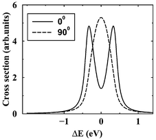 |
| | Fig. 10 The RXS profile for an isolated atomic-like resonance averaged over molecular orientations. Core excitation to the unoccupied σ orbital. The results of the simulations for θ=0° and 90° are shown. θ is the angle between k and e. Γ=0.09 eV. Reproduced from Sałek et al.27
(Copyright American Physical Society). | |
 |
| | Fig. 11 The Doppler splitting of the atomic peak measured for the 1s→σ* core-excited O2 molecule. The spectra were measured for two different angles between the X-ray photon polarization direction and the detection direction. Reproduced from Björneholm et al.28
(Copyright American Physical Society). | |
The resonant photoemission from homonuclear diatomics has a qualitatively different feature.29 When θ=90° the Doppler splitting is suppressed and an interference between scattering channels through the two indistinguishable atoms becomes important. Recent simulations of oxygen20 show that this interference leads to a narrow structure29 on the top of the Doppler broadened atomic peak (Fig. 12).
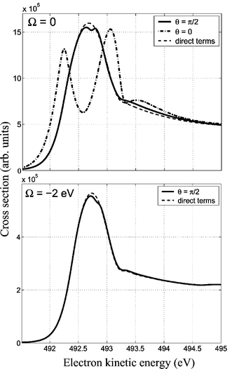 |
| | Fig. 12 The interference dip of the Doppler broadened atomic peak. Resonant photoemission transition ground-state→O1s*→2σ−1g/2σ−1u in gas-phase O2. The dip is diminished for Ω=−2 eV. Reproduced from Baev et al.20
(Copyright American Physical Society). | |
The Doppler effect can even be observed when the core-excited state is bound as long as the lifetime of the core-excited state is of the same order of magnitude as the period of vibrational motion.30 An example is given in Fig. 13: Although the potential of the core-excited state is bound, the wave packet decays only while moving outward.
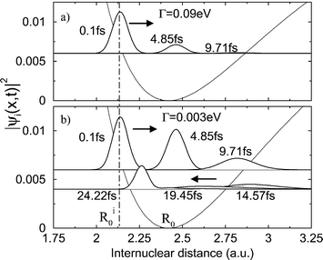 |
| | Fig. 13 The squared wave packet evolving on the core-excited (C 1s–1π*) potential surface of CO for different RXS duration times. The upper plot shows wave packet evolution for a lifetime of the core-excited state of Γ=90 meV. This short lifetime causes the wave packet to decay completely during the first half of the period. Reproduced from Sałek et al.30
(Copyright Elsevier Science). | |
The Doppler effect could not be observed if the lifetime of the core-excited state was much longer because the wave packet would move in both directions during the decay. The effect would not be observed if the lifetime was too short neither: The wave packet would then not have time to move at all. Fig. 14 shows the Doppler shift of the center of gravity and maximum of the resonant Auger spectrum. The observation of this Doppler effect requires oriented samples.30 The Doppler splitting of the atomic-like resonance was observed for oxygen,28 for ozone,31 DF,32 and recently for CF4 and SF6.33
 |
| | Fig. 14 The C 1s–1π* resonant Auger spectra of oriented CO molecules leading to the final state A 1π−11Π. Binding energy=ω−E. The center of gravity positions computed for ϑ=0°, 90°, and 180° are marked with solid, dashed, and circle lines, respectively. The corresponding positions of the cross-section maxima relative to ϑ=90° are shown by arrows. Here ϑ is the angle between k and the radius vector R from O to C. Reproduced from Sałek et al.30
(Copyright Elsevier Science). | |
VIII. Generalized Franck–Condon factors
The generalized FC factors enter not only in RXS theory but also influence spectra measured in photoelectron spectroscopy (PES) as explained in paper.34 The principle is illustrated in Fig. 15.
 |
| | Fig. 15 The GFC factors in X-ray photoionization. a is the size of the ground state wave packet. The phase difference depends on the spatial size of the wave packet, the observation angle as well as on the wavelength of the emitted particle. Reproduced from Gel'mukhanov et al.34
(Copyright American Physical Society). | |
The phase of the electromagnetic field absorbed by the vibrating molecule depends on the vibrational phase. The phase difference depends on the internuclear distance at the moment of absorption as well as on the photon wavelength. The interference between these coherent waves can considerably influence the vibrational profile of the core photoelectron spectra. The interference averages out to a large extent for free molecules but the effect can make a dramatic difference for surface physisorbed molecules: The computed cross sections demonstrating this effect for CO are shown in Fig. 16.
 |
| | Fig. 16 Carbon K-level photoelectron spectra of CO for different photon energies. k↑↓p. The left-hand panels (a,b,c) show the spectra for photoelectrons ejected parallel to the molecular axis. The case of randomly oriented molecules is shown in panels (d,e,f). The unfilled plots show the spectra calculated without the phase factor exp(iα(k−p)·R)
(the spectra are normalized so that the low-energy peak has the same intensity in the two spectra). The shaded plots are calculated making use of the GFC factors. The adiabatic C 1s ionization potential (0–0 transition) is equal to 295.9 eV. Reproduced from Gel'mukhanov et al.34
(Copyright American Physical Society). | |
IX. RXS under core excitation to dissociative states
The RXS spectral profile has two major contributions which are formed by the decay transition in the molecular and dissociative regions35 (Fig. 17). The initially localized wave packet moves to the dissociative region and spreads. During this propagation the wave packet decays continuously to the final state. The decay processes near the equilibrium geometry form the so-called molecular band. When the wave packet approaches the region of dissociation, the decay is identical to that of the fragments. This decay channel forms narrow atomic-like resonances when the dissociation fragment is just a single atom.
 |
| | Fig. 17 The formation of molecular and atomic bands in RXS. The broad background is attributed to the decay in the molecular region while the atomic peak originates from the decay after dissociation. Reproduced from Gel'mukhanov and Ågren2
(Copyright Elsevier Science). | |
The scattering process depends strongly on the energy of the incident photon. The off-resonance excitation decreases the total magnitude of the cross section but the atomic features vanish faster than the molecular ones with detuning. The spectrum becomes similar to the direct photoionization cross section for large detuning. Detuning can then be treated as a parameter controlling dissociation in the core-excited state.
Since the atomic peak is localized at a constant position and the molecular background moves with changed detuning, these contributions to the cross section can overlap for a range of detuning parameters and the atomic-like resonance can be embedded in the molecular background. Such a case leads to an interference between the molecular and atomic decay channels. The most interesting case is destructive interference which can produce an atomic hole replacing the atomic peak.
The atomic hole was first predicted in paper12 for a 4Π state of HCl (Fig. 18). This state is effectively forbidden electronically and has therefore too small cross section to be observed. However, the atomic hole could be observed for another final state 4σ−1
(2Σ+) (Fig. 19). The theoretical cross section for this state is shown in Fig. 20 where we have taken into account also the direct photoionization cross section to reproduce the experimental ratio between the molecular background and the atomic peak. Both figures show also the same state in the case of DCl, where the hydrogen atom has been replaced by its heavier isotope, deuterium. Both in practice and theory, the hole is gone for DCl. Since the HCl and DCl molecules have the same electronic structure, with only the effective mass being different, we can draw the conclusion that this effect depends on the dissociation speed. Also, the duration of RXS plays a crucial role in the competition between the atomic peak (or hole) and the molecular background. When the RXS duration is short (large detuning or lifetime broadening), the molecule has no time to dissociate and the atomic peak/hole is suppressed.
 |
| | Fig. 18 Above: the RXS cross section for the unbound 4Π final state of HCl for different excitation energies. The RXS cross sections are normalized; the integral cross sections are the same for different excitation energies. γ=0 eV. Below: the region near the atomic hole in more detail. Reproduced from Sałek et al.12
(Copyright American Physical Society). | |
 |
| | Fig. 19 The measured RXS cross section in the 4σ−1 spectral region of HCl and DCl. Reproduced from Feifel et al.36
(Copyright American Physical Society). | |
 |
| | Fig. 20 Theoretical calculation of the observed HCl atomic hole. The calculation demonstrates the appearance of a hole for HCl and its absence for DCl. Reproduced from Feifel et al.36
(Copyright American Physical Society). | |
The molecular band and atomic peak have qualitatively different dispersion laws. While the molecular background shifts up with increasing incident photon energy ω, the position of the atomic peak is constant and does not depend on ω. Furthermore, the resonance (Raman) narrowing below the core-excited lifetime width, which takes place for normal (here the molecular band) resonant X-ray scattering, does not hold for the dissociative atomic peaks.35,37–39
Because a set of conditions must be met the observation of the atomic hole is nontrivial. The core-excited state has to be dissociative and the core-excited state lifetime must be sufficiently long in order to observe atomic features in the spectrum. The bound final states have their molecular part shifted away from the atomic peak and it is unlikely to observe the atomic features with the incident photon energy detuned sufficiently to compensate for this shift, because the cross section then becomes small. The dissociative final state should be separated in the energy from the other states and be the only one having that particular atomic limit: the atomic peaks originating from other states would cover the hole otherwise. Also, the dissociation speed has some substantial significance, as can be understood from the DCl case.
A. Suppression of atomic peaks
It can prove difficult to reproduce the complete RXS spectrum of a molecule which includes many overlapping final states. One would like also to be able to include the direct channel with the weight computed by ab initio methods instead of estimating it from the experimental data. In order to compute such a spectrum, one needs to possess not only complete knowledge of all final states in the energy region of interest but also all the relevant transition moments. These involve a description of free Auger electrons which requires special techniques.40,41
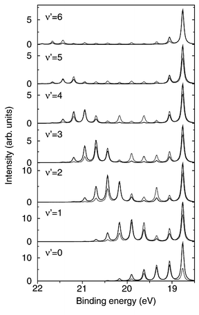
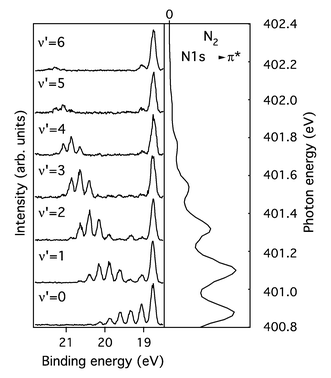
Let us analyze hydrogen fluoride,42 the lightest molecule in the group of halides. This molecule has a photoelectron spectrum where the spectator part contains strong atomic lines and a participator part with only molecular backgrounds (Fig. 21). This molecule serves also as an exception from the participator–spectator classification: Frequently, the source and target orbitals of the electron decay occurring in the scattering process can be easily identified. When the electron excited by the incident photon takes part in the decay process, the associated state is called a “participator”. When the excited electron remains in its place, the associated state is called a “spectator”. In the case of the core-excited HF molecule having an 1σ−1σ* electronic configuration, the spectral feature associated with the final electronic state 1π−1 is called a participator, and the spectral feature associated with 1π−2σ* is a spectator. This naming convention is useful because these two types of states behave differently in the RXS process. The spectator states have negligible direct photoionization cross section because two electrons are displaced compared to the ground state configuration and because photoionization is basically a one-electron process. They have, however, usually large resonant cross sections. The participator states, on the other hand, usually have non-vanishing direct photoionization cross sections.
 |
| | Fig. 21 The experimental HF spectrum. Reproduced from Sałek et al.42
(Copyright Elsevier Science). | |
The presence of a strong direct ionization contribution may also lead to an apparent quenching of the atomic peak: see the lowest HF participator states on Fig. 22. While the purely resonant contribution associated with these states has evident atomic features, these features are small compared to the direct photoionization background. This is essentially due to the nuclear broadening of the resonant profile. Such a “vibrational broadening” results in a dynamical suppression of the resonant cross section due to the invariance of the total area of the resonant profile.41
 |
| | Fig. 22 Theoretical calculation of the RXS spectrum of HF including resonant, direct and interference channels for seven distinct final electronic states. The spectrum includes also lower participator bound states marked with P. Reproduced from Sałek et al.41
(Copyright American Institute of Physics). | |
In the case of HF the ab initio calculations included potential curves for 9 final electronic states; 3 participators and 6 spectators, and the accompanying transition moments. Two of the spectators states 1π−2σ*
(2Σ−) and 1π−2σ*
(2Δ) could be discarded from further calculations because they lead to negligibly small Auger decay rates.
B. Role of avoided crossings
The distinction between participator and spectator channels disappears when two such configurations belonging to the same symmetry cross. The electronic character of the state will then change with the internuclear distance and so will the transition moments. The calculations for the hydrogen fluoride molecule exemplify the role of avoided crossings on the RPE spectra, here the avoided crossing between the 2σ−1 and 3σ−2σ* states, because the Auger decay rates associated with the two electronic configurations involved are diametrically different. 2σ−1 is a participator configuration, with a large direct photoionization cross section and rather small resonance cross section, while 3σ−2σ* has the electronic configuration of a spectator state with a close to zero photoionization cross section and substantial resonance cross section. The adiabatic states defined by the linear combination of these configurations switch the transition moments at the avoided crossing giving rise to a strong R-dependence of the respective transition moments. This results in a sharp switching of the Auger decay rates after the avoided crossing point and changes qualitatively the role of the nuclear dynamics in the formation of the RPE spectra (see paper41 for details).
X. Role of scattering duration on electronic degrees of freedom
It was demonstrated above that for nuclear degrees of freedom the frequency detuning, Ω, acts as an X-ray camera shutter by regulating the duration time, eqn. (5), of the scattering process. It is not hard to see that the concept of a duration time works also for electronic degrees of freedom.2,43 We illustrate this by considering the classical problem of the relaxation of a valence electron in the field of a core hole, addressing radiative RXS from linear polyenes. The RXS spectra are depicted in Fig. 23, which compares the strict RXS profiles with the ones neglecting interaction between core hole and valence electrons (frozen orbital approximation). We see clearly that the increase of the detuning almost completely eliminates the relaxation. The physical reason of this effect is that the relaxation of the valence electrons in the intermediate core excited state requires a time lapse equal to the inverse bandwidth, Δel, and that the valence shell has no time to relax in the core hole field when the scattering is faster than the relaxation | |  | (19) |
 |
| | Fig. 23 RXS spectra of linear polyene with N=4 carbons for different detunings, Ω=Ω−I. Ω′=ω′−I. I is the ionization potential of the C1s core level. The elastic peak is marked by a vertical arrow. Solid lines correspond to the strict solution of the Keldysh–Dyson equation, while the dashed lines represent the calculations in the frozen orbital (unrelaxed) approximation. um is the strength of the electron–hole interaction. Reproduced from Privalov et al.43
(Copyright American Physical Society). | |
XI. Role of the pulse shape
One can show44 that the RXS spectral profile under pulsed excitation has a form similar to that of the stationary case:
| σf(ω,E)=∫dω1σ0f(ω1,E)Φ(ω1−ω) |
Here σ0f(ω,E) is the cross section of stationary RXS under monochromatic excitation. According to the Wiener–Khintchine theorem the spectral density of incident radiation is given by the Fourier transform of the autocorrelation function| |  | (20) |
These equations show that the integral RXS cross section does not depend on the pulse duration.
However, the peak intensity is sensitive to the pulse duration. To illustrate this we consider a Gaussian pulse with duration τ. The unit normalized spectral function is Φ(ω)=(τ/√π)exp(−ω2τ2), which is compatible with an RXS cross section |Ff|2Δ(E−ω+ωf0,Γf) for a long pulse (τΓf≫1) and |Ff|2Φ(E−ω+ωf0) for a short pulse (τΓf≪1). This leads immediately to the conclusion that the peak intensities of final states with short and long lifetimes depend differently on the pulse duration44
| |  | (21) |
XII. Concluding remarks
The purpose of the present work was to present a unifying look at contemporary theory and applications of X-ray Raman scattering, emphasizing the dynamical properties of this process. A few small molecules have been employed as test samples to illustrate the various aspects of the theory. The usefulness of the time-dependent methods is obvious from their applications which now cover a representative cross section of physically interesting problems in X-ray Raman scattering. Although the diversification of these methods already has been driven quite far, one can foresee development in several aspects; of the basic methodology as well as of a widening of the scope of systems and phenomena that can be investigated. It is our hope that the present review has provided ideas on some problems for future work in the field of X-ray Raman scattering.
Acknowledgements
We thank Prof. Vincenzo Carravetta and Dr Timofei Privalov for fruitful collaboration on resonant photoemission. The collaboration with the experimentalists in Uppsala and at MAXLAB laboratory in Lund is very productive. We thank Raimund Feifel, Florian Burmeister, Stacey Sorensen, Margit Bäßler, Maria-Novella Piancastelli, Karoline Wiesner, Olle Björneholm, Arnaldo Naves-de-Brito, Svante Svensson for valuable discussions and for allowing us to reproduce some of their experimental spectra (Figs. 8, 12, 20, 21, 22).
References
-
T. Åberg and B. Crasemann, in Resonant Anomalous X-Ray Scattering. Theory and Applications, ed. G. Materlik, C. J. Sparks and K. Fischer, North-Holland, Amsterdam, 1994, p. 431 Search PubMed.
- F. Gel'mukhanov and H. Ågren, Phys. Rep., 1999, 312, 87 CrossRef CAS.
- G. B. Armen, H. Aksela, T. Åberg and S. Aksela, J. Phys B: At. Mol. Opt. Phys., 2000, 33, 49 CrossRef.
- M. N. Piancastelli, J. Electron Spectrosc. Relat. Phenom., 2000, 107, 1 CrossRef CAS.
- S. L. Sorensen and S. Svensson, J. Electron Spectrosc. Relat. Phenom., 2001, 114–116, 1 CrossRef CAS.
- J. Guo and J. Nordgren, J. Electron Spectrosc. Relat. Phenom., 2000, 110–111, 105 CrossRef CAS.
- J.-E. Rubensson, J. Electron Spectrosc. Relat. Phenom., 2000, 110–111, 135 CrossRef CAS.
- F. de Groot, Chem. Rev., 2001, 101, 1779 CrossRef CAS.
-
W. Heitler, The Quantum Theory of Radiation, Clarendon Press, Oxford, 1966 Search PubMed.
-
A. I. Akhiezer and V. B. Berestetskii, Quantum Electrodynamics, Interscience, New York, 1965 Search PubMed.
-
J. J. Sakurai, Advanced Quantum Mechanics, Addison-Wesley, Reading, MA, 1991 Search PubMed.
- P. Sałek, F. Gel'mukhanov and H. Ågren, Phys. Rev. A, 1999, 59, 1147 CrossRef CAS.
-
M. O. Scully and M. S. Zubairy, Quantum Optics, Cambridge University Press, Cambridge, 1997 Search PubMed.
-
R. W. Boyd, Nonlinear Optics, Academic Press, New York, 1992 Search PubMed.
- F. Gel'mukhanov, P. Sałek, T. Privalov and H. Ågren, Phys. Rev. A, 1999, 59, 380 CrossRef CAS.
- P. Sałek, R. F. Fink, F. Kh. Gel'mukhanov, M. N. Piancastelli, R. Feifel, M. Bäßler, S. L. Sörensen, C. Miron, H. Wang, I. Hjeltje, O. Björneholm, S. Svensson and H. Ågren, Phys. Rev. A, 2000, 62, 62506 CAS.
- V. Hizhnyakov and I. Tehver, Phys. Status Solidi, 1967, 21, 755 Search PubMed.
- F. Kh. Gel'mukhanov, L. N. Mazalov and A. V. Kondratenko, Chem. Phys. Lett., 1977, 46, 133 CrossRef CAS.
- E. J. Heller, R. L. Sundberg and D. Tannor, J. Phys. Chem., 1982, 86, 1822 CrossRef CAS.
- A. Baev, F. Gel'mukhanov, P. Sałek, H. Ågren, K. Ueda, A. de Fanis, K. Okada and S. Sorensen, Phys. Rev. A, 2002, 66, 22509 CrossRef CAS.
- F. Kaspar, W. Domcke and L. S. Cederbaum, Chem. Phys., 1979, 44, 33 CrossRef CAS.
- A. Cesar, H. Ågren and V. Carravetta, Phys. Rev. A, 1989, 40, 187 CrossRef CAS.
-
W. Eberhardt, in Applications of Synchrotron Radiation. Springer Series in Surface Sciences, ed. W. Eberhardt, Springer-Verlag, Berlin, Heidelberg, 1995, 35, 203 Search PubMed.
- M. N. Piancastelli, R. F. Fink, R. Feifel, M. Bässler, S. L. Sorensen, C. Miron, H. Wang, I. Hjelte, O. Björneholm, A. Ausmees, S. Svensson, P. Sałek, F. Kh. Gel'mukhanov and H. Ågren, J. Phys. B: At. Mol. Opt. Phys., 2000, 33, 1819 CrossRef CAS.
- F. Gel'mukhanov and L. N. Mazalov, Opt. Spektrosk., 1977, 42, 659 (
Opt. Spectrosc. (Transl. of Opt. Spektrosk.)
, 1977
, 42
, 371
) Search PubMed.
- F. Gel'mukhanov and H. Ågren, Phys. Rev. A, 1994, 49, 4378 CrossRef CAS.
- P. Sałek, F. Gel'mukhanov, H. Ågren, O. Björneholm and S. Svensson, Phys. Rev. A, 1999, 60, 2786 CrossRef CAS.
- O. Björneholm, M. Bässler, A. Ausmees, I. Hjelte, R. Feifel, H. Wang, C. Miron, M. N. Piancastelli, S. Svensson, S. L. Sorensen, F. Gel'mukhanov and H. Ågren, Phys. Rev. Lett., 2000, 84, 2826 CrossRef CAS.
- F. Gel'mukhanov, H. Ågren and P. Sałek, Phys. Rev. A, 1998, 57, 2511 CrossRef CAS.
- P. Sałek, F. Gel'mukhanov, T. Privalov and H. Ågren, Chem. Phys. Lett., 2000, 328, 425 CrossRef CAS.
- L. Rosenqvist, K. Wiesner, A. Naves de Brito, M. Bässler, R. Feifel, I. Hjelte, C. Miron, H. Wang, M. N. Piancastelli, S. Svensson, O. Björneholm and S. L. Sorensen, J. Chem. Phys., 2001, 115, 3614 CrossRef CAS.
- K. Wiesner, A. Naves de Brito, S. L. Sorensen, F. Burmeister, M. Gisselbrecht, S. Svensson and O. Björneholm, Chem. Phys. Lett., 2002, 354, 382 CrossRef CAS.
-
M. Kitajima, K. Ueda, S. Sorensenet al., in preparation.
- F. Gel'mukhanov, P. Sałek and H. Ågren, Phys. Rev. A, 2001, 64, 12504 CAS.
- F. Gel'mukhanov and H. Ågren, Phys. Rev. A, 1996, 54, 379 CrossRef CAS.
- R. Feifel, F. Burmeister, P. Sałek, M. N. Piancastelli, M. Bäßler, S. L. Sörensen, C. Miron, H. Wang, I. Hjeltje, O. Björneholm, Naves de Brito, F. Kh. Gel'mukhanov, H. Ågren and S. Svensson, Phys. Rev. Lett., 2000, 85, 3133 CrossRef CAS.
- E. Kukk, H. Aksela, S. Aksela, F. Gel'mukhanov, H. Ågren and S. Svensson, Phys. Rev. Lett., 1996, 76, 3100 CrossRef CAS.
- F. Gel'mukhanov and H. Ågren, Phys. Rev. A, 1996, 54, 3960 CrossRef CAS.
- E. Pahl, H.-D. Meyer and L. S. Cederbaum, Z. Phys. D, 1996, 38, 215 CrossRef CAS.
- B. Schimmelpfennig, B. M. Netsmann and S. D. Peyerimhoff, J. Electron Spectrosc. Relat. Phenom., 1995, 74, 173 CrossRef CAS.
- P. Sałek, V. Carravetta, F. Kh. Gel'mukhanov and H. Ågren, J. Chem. Phys., 2002, 116, 629 CrossRef CAS.
- P. Sałek, V. Carravetta, F. Kh. Gel'mukhanov, H. Ågren, B. Schimmelpfennig, M.-N. Piancastelli, S. L. Sorensen, R. Feifel, I. Hjelte, M. Bässler, S. Svensson, O. Björneholm and A. Naves de Brito, Chem. Phys. Lett., 2001, 343, 332 CrossRef CAS.
- T. Privalov, F. Gel'mukhanov and H. Ågren, Phys. Rev. B, 2001, 64, 165116 Search PubMed.
- F. Gel'mukhanov, P. Sałek, A. Shalagin and H. Ågren, J. Chem. Phys., 2000, 112, 5593 CrossRef CAS.
|
| This journal is © the Owner Societies 2003 |
Click here to see how this site uses Cookies. View our privacy policy here. 
