Ethers, crown ethers and 18-crown-6 K+ complexes at a water/SC-CO2 interface: a molecular dynamics study†
Philippe
Vayssière
and
Georges
Wipff
*
Institut de Chimie, 4 rue B. Pascal, 67 000, Strasbourg, France. E-mail: wipff@chimie.u-strasbg.fr
First published on 19th November 2002
Abstract
We present a molecular dynamics study of 18C6, 15C5 crown ethers and their acyclic polyether analogues at the water/supercritical-CO2 interface. The aqueous and CO2 components form distinct phases, separated by an interface, where in all systems, the ethers are found to concentrate. Simulations of the inclusive K+⊂18C6 Pic− complexes led to decomplexation of K+ and accumulation of the crown ethers on the CO2 side of the interface, while Pic− anions stack in the aqueous phase. When the K+ cations are constrained to form inclusive complexes with 18C6, all complexes concentrate at the interface, be the counterions free to move, or constrained to coordinate to K+. In the presence of nitric acid, modeled by equimolar mixtures of HNO3, NO3− and H3O+ forms, the ethers remain surface active, as does the neutral form of the acid. These simulations demonstrate the importance of interfacial phenomena in assisted ion extraction to supercritical-CO2.
Introduction
The interface between water and “oil” (generally an organic liquid immiscible with water) plays a key role in ion assisted liquid–liquid extraction systems as the hydrophilic ions (initially in water) and the hydrophobic extractant molecules (initially in “oil”) are generally assumed to meet at this peculiar region.1–5 However, the precise nature of the interface and the detailed extraction mechanism are unknown from experiment alone.1 Computer simulations provide microscopic pictures of liquid–liquid interfaces and of the distributions of the partners involved in the extraction process. Most of the related studies have so far modeled “oil” by simple liquids such as chloroform,6,7 or dichloroethane.8,9 In this paper, we consider supercritical-CO2 “SC-CO2”, which represents a promising ecological alternative in liquid–liquid extraction of metals from solid or liquid matrices.10–17 So far, there are few theoretical studies dealing with aqueous SC-CO2 interfaces.18–23In this paper, we focus on ethers and crown ethers which extract alkali cations through hydrophobic media24,25 and have been recently shown to also extract these cations to SC-CO2.11,26 For instance, in the presence of CO2-philic fluorinated counterions, polyethyleneglycol ligands,26 as well as the cyclic DBC6 (dibenzo-18-crown-6) and 15C5 (15-crown-5) ethers extract Na+ and K+ from water to SC-CO2.26 The selective extraction of Sr2+ by DC18C6 (dicyclohexyl-18-crown-6) has been also reported.16 On the computational side, these molecules, and 18C6 in particular, represent excellent candidates for testing new methodologies and techniques (see e.g.ref. 27 and references cited therein). They are relatively simple in terms of constitution, but display important features of systems involved in recognition processes, such as flexibility, adaptation to the complexed guest, as a function of solvent and environment. More specifically, we consider two crown ethers of different sizes, 18C6 and 15C5 (Fig. 1), as well as their acyclic analogues (pentaglyme and tetraglyme) which will be labeled in short 18n6 and 15n5 (“n” standing for “normal”). They are simulated at a water/SC-CO2 interface explicitly represented at the molecular level. Some exploratory simulations with monomeric 18C6 and 15C5 systems showed that they remain adsorbed at the interface during the whole simulation (0.5 ns). Generally speaking, surface activity implies an increased concentration at the interface, and has therefore to be modeled by more concentrated systems. This is why we consider systems with 12 polyether molecules in the simulation box, corresponding to aqueous concentrations of about 0.2 mol L−1. In the case of 18C6, we also consider a more concentrated system (36 18C6 molecules), obtained by dissolution of a piece of crystal, in which the molecules are packed together. The simulations thus provide insights into the result of the dissolution process. As K+ is extracted by 18C6 analogues to the CO2 phase, we decided to also simulate K+⊂18C6 complexes in the presence of picrate (Pic−) counterions that are often used in extraction or transport experiments. These systems with uncomplexed and complexed ethers (noted A–E; see Table 1 for definitions) are formally pH neutral. We finally consider systems with nitric acid and ethers at similar concentrations. Ion extraction indeed often proceeds from acidic solutions, and we wanted to investigate the interplay of these solute molecules, in terms of the properties of the interface, and also look for possible acid⋯ether hydrogen bonding interactions between, e.g. H3O+ and some ethers.28 The corresponding acidic systems G–J are characterized in Table 1.
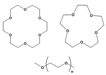 | ||
Fig. 1 The simulated ligands: 18C6, 15C5 and their open analogues 18n6 (n![[thin space (1/6-em)]](https://www.rsc.org/images/entities/char_2009.gif) =5), 15n5 (n=4). =5), 15n5 (n=4). | ||
=18 (HNO3, H2O, H3O+, NO3−). Concentrations of ether/acid (in systems G–J) are relative to the aqueous phase
| Systems | Concentration/mol L−1 | Number of molecules | Box size (SC-CO2+water)/Å3 |
Time/ns | ||
|---|---|---|---|---|---|---|
| CO2 | water | |||||
| Monomer 15C5 | 0.029 | 753 | 1995 | 39×40×(43+37) |
0.6 | |
| Monomer 18C6 | 0.032 | 653 | 1724 | 38×38×(41+36) |
0.3 | |
| A | 12 15C5 | 0.59 | 551 | 1054 | 34×32×(45+31) |
1.2 |
| B | 12 18C6 | 0.54 | 570 | 1093 | 34×34×(47+32) |
0.9 |
| C | 12 15n5 | 0.45 | 569 | 1330 | 37×37×(39+32) |
0.6 |
| D | 12 18n6 | 0.37 | 678 | 1820 | 37×36×(32+40) |
0.6 |
| E | 36 18C6 | 1.09 | 637 | 1542 | 38×36×(47+40) |
1.2 |
| F | 12 18C6, 12 K+, Pic− | 0.36 | 678 | 1654 | 44×33×(46+38) |
1.2 |
| G | 12 15C5, “acid” | 0.39/0.6 | 475 | 1463 | 37×37×(34+37) |
1.2 |
| G′ | Like G
(vol.−9%) |
0.44/0.66 | 475 | 1463 | 36×35×70 |
1.2 |
| H | 12 18C6, “acid” | 0.40/0.6 | 458 | 1433 | 37×36×(34+37) |
1.2 |
| H′ | Like H
(vol.−7%) |
0.44/0.66 | 458 | 1433 | 36×35×70 |
0.8 |
| I | 12 15n5, “acid” | 0.39/0.6 | 475 | 1463 | 37×36×(34+38) |
1.2 |
| J | 12 18n6, “acid” | 0.24/0.4 | 813 | 2462 | 43×43×(40+45) |
1.2 |
It is important to mention that, there are, so far, no experimental data on the interfacial behavior of the studied systems in supercritical conditions. It will be shown in the following that they display marked similarities with other water/“oil” interfaces studied in standard conditions, for which the conclusions drawn from the simulation results are consistent with experimental data (e.g. surface tension measurements, kinetic models of extraction, surface spectroscopy studies, interfacial electrochemistry). Discussions can be found in ref. 29–31.
Methods
The simulations were performed with the modified AMBER5.0 software32 where the potential energy is described by a sum of bond, angle and dihedral deformation energies, and pair wise additive 1–6–12 (electrostatic+van der Waals) interactions between non-bonded atoms. | U=∑bondsKr(r−req)2+∑anglesKθ(θ−θeq)2+∑dihedrals∑nVn(1+cosnϕ)+∑i<j[qiqj/Rij−2εij(Rij*/Rij)6+εij(Rij*/Rij)12] |
The ether and Pic− charges (from ref. 33 and 34, respectively) and AMBER atom types used for the simulations are given in Fig. 2. The K+ parameters were adopted from Åqvist.35 Water was represented with the TIP3P model.36 For SC-CO2, we used the parameters of Murthy et al.:37 charges qC=0.596e, qO=−0.298e and van der Waals parameters RO*=1.692 Å, RC*=1.563 Å and εO=0.165 kcal mol−1, εC=0.058 kcal mol−1. All O–H, C–H bonds and the C![[double bond, length half m-dash]](https://www.rsc.org/images/entities/char_e006.gif) O bonds of CO2 were constrained with SHAKE, using a time step of 2 fs. The intramolecular electrostatic and van der Waals 1–4 interactions were scaled down by a factor 2.0. Non-bonded interactions were calculated with an atom-based cutoff of 12 Å for all systems, in conjunction with a reaction field RF correction to the coulombic interactions.38 This model assumes that the charge distribution within a sphere of cutoff radius interacts with a polarizable dielectric medium, and prevents discontinuities of the potential energy at the cutoff boundaries. Tests with a larger cutoff (15 Å+RF) and with a 13 Å cutoff+PME Ewald summation were also performed on the 18C6 K+ complexes. The non-bonded pair lists were updated every ten steps.
O bonds of CO2 were constrained with SHAKE, using a time step of 2 fs. The intramolecular electrostatic and van der Waals 1–4 interactions were scaled down by a factor 2.0. Non-bonded interactions were calculated with an atom-based cutoff of 12 Å for all systems, in conjunction with a reaction field RF correction to the coulombic interactions.38 This model assumes that the charge distribution within a sphere of cutoff radius interacts with a polarizable dielectric medium, and prevents discontinuities of the potential energy at the cutoff boundaries. Tests with a larger cutoff (15 Å+RF) and with a 13 Å cutoff+PME Ewald summation were also performed on the 18C6 K+ complexes. The non-bonded pair lists were updated every ten steps.
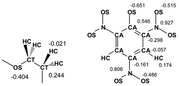 | ||
| Fig. 2 Amber atom types and atomic charges of ether fragments and Pic−. | ||
The representation of acidity in force field methods is problematic, as the latter cannot properly account for proton transfer processes, and require an a priori choice of the protonated/deprotonated species. As this is not precisely known from experiment in heterogeneous conditions, we decided to model nitric acid as (HNO3, H3O+ NO3−)18, i.e. an equimolar mixture of neutral and ionic forms, which represent the dominant contributions in organic and aqueous phases, respectively. This corresponds to about 0.6 M aqueous solutions where the possible formation of CO3H2 acid is neglected for simplicity.
The CO2/water interface has been built as indicated in ref. 18 and 39 starting with adjacent boxes of CO2 and pure water (Fig. 3). The corresponding densities are 0.80 and 1.0 respectively. For CO2, this is above the critical density (0.47 g cm−3 at 304 K) and close to the experimental density of 0.79 g cm−3 at 345 K and a pressure of 30 MPa.40 All systems were represented with 3D periodic boundary conditions, thus starting with alternating slabs of water and CO2 separated by an interface.
The solutes were first placed at the interface, as shown in Fig. 3. Initially, the 18C6 molecules were of D3d symmetry in all systems (excepted in E where they were Ci), 15C5 was modelbuilt (OC–CO dihedrals of g−, g+, g+, t and g+ type), while 18n6 and 15n5 were “all-trans”. After energy minimization, MD was run at 350 K and constant volume, first for 50 ps with the solute frozen (in order to relax the solvent molecules), followed by 50 ps of free MD and by the production stage. The temperature was monitored by separately coupling the water, CO2 and solute subsystems to thermal baths at the reference temperature (350 K) with a relaxation time of 0.2 ps for the solvents and 0.5 ps for the solutes, using the Berendsen algorithm.41
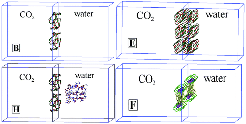 | ||
| Fig. 3 The simulation box, with the starting arrangements of systems B
(12 18C6), E
(36 18C6), H
(12 18C6+18 (NO3H, NO3−, H3O+)) and F
(12 K+⊂18C6 Pic−). Similar arrangements were considered for the analogous systems. The z-axis is perpendicular to the interface. | ||
The mixing/demixing simulations started at the end of the dynamics with the preformed interface, where the system was heated for about 0.4 ns at 700 K and the electrostatic interactions were scaled down by a factor of 100 in order to enhance the mixing of hydrophobic and hydrophilic species. This led to “chaotic mixtures” of water, CO2 and the solutes. The demixing simulation was then initiated by resetting the temperature to 350 K, and the dielectric constant of the medium to 1.0.
The results have been analyzed as described in ref. 39 and 42 from the trajectories saved every 0.5 ps. The interface position was instantaneously defined by the intersection of the solvent density curves. The percentage of species “near the interface” was calculated from the average number of species (last 0.5 ns) which sit within a distance of 10 Å from the interface, which corresponds to about half of the average interfacial width 〈e〉. The instantaneous width e was defined as the difference in z positions of water molecules at the interface zmax(t)−zmin(t), where the z direction is perpendicular to the interface.19 The energy component analysis of the trajectories was performed in terms of pairwise additive contributions (electrostatic, van der Waals and total) of the solvents (water and CO2) and different solutes. The results are given in Table S1 (see Electronic supplementary information (ESI)†). The hydration of the solute is characterized by the analysis of the radial distribution functions RDFs of water around the center-of-mass of the ethers or K+.
Results
In all systems, the aqueous and CO2 phases form two distinct phases, linked by an “interface”. The latter is inherently dynamic in nature and non-planar. In most cases, also one finds a peak of ether concentration at this interface. Details are given below. Unless otherwise indicated, all results correspond to standard simulations where the solute molecules initially sit at the prebuilt interface.1 The pH-neutral solutions of ethers at the interface
The pH-neutral systems A–D correspond to solutions of 12 crown ether molecules 15C5, 18C6, and of their acyclic analogues 15n5 and 18n6. A–D correspond to an aqueous phase concentration of about 0.5 mol L−1, while system E is more concentrated. Typical snapshots at the end of the simulations and average density curves are given in Fig. 4.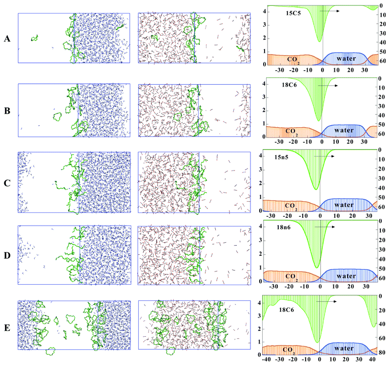 | ||
| Fig. 4 The pH-neutral systems with ethers (A–E) at the water/CO2 interface. Left and middle: snapshots at the end of the simulation, with CO2 (left) and water (right) not shown for clarity. Right: average density curves for the solvents and solutes (arbitrary units). Averages from the last 0.4 ns. The right hand side ordinate of the density curves corresponds to the ether solutes. | ||
At the end of the dynamics, systems A–E consist of two well-defined phases, separated by an interfacial region. About 20 CO2 molecules diffused to water, while the CO2 phase remains dry, in agreement with the corresponding low miscibility of these liquids.43,44 In A–D, the ether molecules concentrate at the initial interface, as shown by a well-defined peak in the density curves and the snapshots at the end of the dynamics. There is no significant difference between the interfacial proportion of the different ethers, which is 80–90% in all systems (Table 2). In some cases, one to two ether molecules diffuse to the CO2 phase, therefore losing contact with the aqueous phase. As a result, the ether density peaks are asymmetrical, and less abrupt on the CO2 side than on the waterside of the interface. During the dynamics, the cyclic and acyclic ethers undergo many conformational changes, due to the high temperature conditions. In the case of 18C6, only 10% of the crowns are of D3d type during the last 0.2 ns. However, most of the OC–CO dihedrals are gauche
(94%, in B and 85% in C and D), allowing for bridging hydrogen bonding interactions with water. Indeed, according to an energy component analysis (Table S1†), the ethers display significant attractions with water. The average per ether molecule interaction energy with water ranges from −17.4 kcal mol−1
(in system A) to −23.6 kcal mol−1
(in D) and is mostly (≈75%) of electrostatic origin. The corresponding interaction energies with CO2 are weaker (from −7.1 to −9.9 kcal mol−1) and mostly (≈90%) of van der Waals origin. As expected, the larger ethers interact more than their smaller analogues with both phases (18C6>15C5 and 18n6>15n5), while acyclic ethers interact better than their cyclic analogues with both phases (18n6>18C6 and 15n5>15C5). This analysis thus shows the importance of water attraction by the interfacial ether molecules. Visual analysis of the trajectories with 18C6 shows that about half of the crowns are hydrogen bonded to one bridging water molecule, and that these hydrogen bonds are quite labile, due to high temperature. This contrasts with the pure aqueous phase behavior of 18C6 at 300 K, where the D3d form is stabilized by firmly hydrogen bonded bridging water molecules.45
=Swat/xy). x and y are the dimensions of the box in the plane of the interface, given in Table 1
| System | Ether | HNO3 | H3O+ | NO3− | 〈e〉/Å | 〈Swat〉/Å2 | R |
|---|---|---|---|---|---|---|---|
| A | 81 | — | — | — | 17±2 |
3050±480 |
2.76 |
| B | 90 | — | — | — | 18±2 |
3100±480 |
2.71 |
| C | 90 | — | — | — | 17±2 |
3560±370 |
2.60 |
| D | 92 | — | — | — | 19±2 |
4650±580 |
3.37 |
| E | 27 (27) | — | — | — | 29±5 |
6050±1250 |
4.35 |
| F | 56 | — | — | — | 19±3 |
3900±480 |
2.72 |
| G | 83 | 29 | 30 | 24 | 19±3 |
4000±600 |
2.96 |
| G′ | 84 | 48 | 29 | 18 | 20±3 |
4100±650 |
3.30 |
| H | 72 | 55 | 29 | 21 | 18±3 |
3950±530 |
2.95 |
| H′ | 61 | 37 | 27 | 22 | 17±3 |
3300±430 |
2.60 |
| I | 89 | 36 | 25 | 17 | 18±3 |
3650±550 |
2.70 |
| J | 99 | 33 | 31 | 19 | 18±3 |
4900±640 |
3.65 |
The water/CO2 interfaces are very irregular (Fig. 4) and dynamic in nature. On the average, the ether containing interfaces are about 18 Å thick, which is about 8 Å wider than the water/chloroform interface simulated at 300 K.39 As an index of its roughness, we calculated the ratio R between the surface of water Swat at the interface, and the xy area (Table 2). R is about 2.7 for the systems A–D, which is larger than the value obtained for the corresponding neat interface (R=2.4)19 or at a chloroform/water interface at 300 K (R=1.7),46 as a result of larger diffusion of the CO2 and H2O molecules in the supercritical conditions. The large fluctuations of Swat area (Table 2) are also indicative of the surface dynamics and roughness.
System E deals with a more concentrated solution of 18C6 (about 0.33 mol L−1) and reveals interesting differences, compared to system B. Initially, all 18C6 molecules formed a tightly packed arrangement extracted from the X-ray structure of 18C6 uncomplexed, where the crowns are of Ci symmetry.47 At the beginning of the dynamics (0 ns), they were all sitting right at the interface, as shown in Fig. 3. Rapidly, they underwent conformational changes, and diffused on both sides of the CO2 phase. At the end of the dynamics, they are equally (27%+27%) distributed in the CO2 phase onto the two interfaces, instead of concentrating near the initial one, indicating that the sampling and simulation time are sufficient to allow for major reorganization of the system. The CO2 phase contains about 46% of the ethers, some of them being in contact with the interface. As in system B, the CO2 phase contains a few water molecules, forming transient hydrogen bonded oligomers. It has been shown that the Ci form of 18C6, although being intrinsically the most stable one, displays a poor affinity for water, compared to the D3d form45 and it is interesting to notice that at the end of the dynamics none of the crowns are Ci, while 37% are D3d
(averages during the last 0.2 ns). About 95% of the crowns display gauche arrangements of the OC–CO dihedrals, which allows for favorable interactions with water. Some 18C6 molecules seem to sit on the aqueous side of the interface (Fig. 4), but are in fact surrounded by a mixed CO2–water microenvironment.
2 The K+⊂18C6 Pic− complexes at the interface
The simulation of the 12 K+⊂18C6 Pic− system F started with a packed arrangement of the inclusion complexes of 18C6, extracted from the corresponding X-ray structure.48,49 Initially, all complexes were at the interface, K+ being in close contact with one phenolate- and one nitro-oxygen of Pic−. Unless otherwise specified, the results correspond to the “standard” 12 Å+RF protocol. After 1 ns of dynamics (see Fig. 5) one observes a spectacular reorganization of the system, as nearly all cations decomplexed, presumably do to the high temperature and kinetic energy. Indeed, when the simulation was repeated at 300 K for up to 2 ns, only 50% of the cations decomplexed. At 350 K (system F), they diffused to water where they are more soluble, accompanied by the Pic− counterions which form remarkable stacking arrangements. A columnar arrangement of up to eleven anions is observed at the end of the dynamics, surrounded mostly by water and by a few K+ ions. All freed 18C6 molecules adsorbed on the CO2-side of the interface, as in the simulation B of the uncomplexed crowns. Their conformation was again of D3d type, involving a dominant population (95%) of gauche OC–CO dihedrals, on the average stabilized by one bridging H2O molecule. One K+ complex migrated to the CO2 phase, where the cation is sandwiched by two crown ethers. It is not accompanied by Pic− anions, however, presumably because the latter are not hydrophobic enough and/or display too weak interactions with the complex to follow it in the CO2 phase. Repeating the F simulation with different protocols for the boundaries (13 Å+PME Ewald summation, or 15 Å+RF correction) leads to similar conclusions, as far as the cation decomplexation and distribution of the resulting species are concerned (Fig. 5). Minor differences concern the Pic− anion stacks which are smaller (of two to five species) as expected, but also sit in water, surrounded by K+ cations. No cation remains complexed nor is extracted, but one to three free crowns are found in CO2
(13+PME calculation).
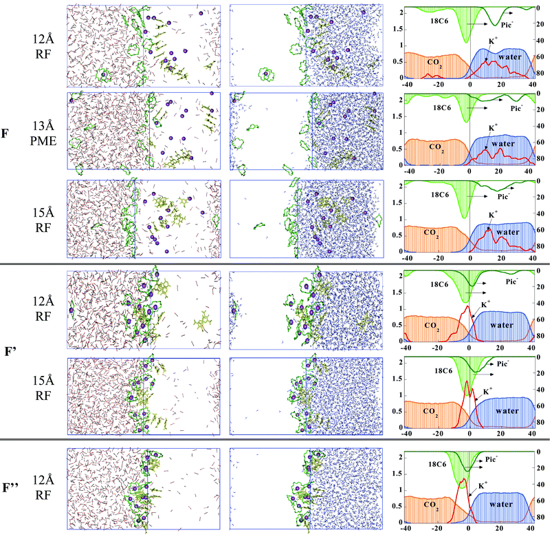 | ||
| Fig. 5 The pH-neutral systems with 12 K+⊂18C6 Pic− “complexes” at the water/CO2 interface. See Table 1 for definitions. Simulations without constraints (F), with constraints on O⋯K+ distances (F′) plus K+⋯Pic− distances (F″) with different protocols. The right hand side ordinate of the density curves corresponds to the ether and Pic− species. | ||
The simulation of system F was repeated with two variants (noted F′ and F″), with the aim to force the stability and hydrophobicity of the K+ complexes. (i) First (F′), by imposing the K+ cations to remain complexed by 18C6 (for this purpose, six K+⋯O distances were constrained at 2.92 Å, with a restraining potential of 5 kcal mol−1) and everything else was free of constraints. Thus, K+ is shielded by 18C6, but may still coordinate anions and/or water molecules along the “C3 symmetry” axis of the complex. (ii) Second (F″), by additionally constraining the Pic− anions to retain their initial coordination distance to K+
(K+⋯Ophenolate=2.74 Å), therefore forming neutral complexes, a priori more suitable for extraction to the CO2 phase. The corresponding results are illustrated in Fig. 5. In both cases, the majority of the complexes remain at the interface and are attracted by water. In F′, the K+⋯water attraction amounts to ≈40 kcal mol−1 and, according to the analysis of the RDFs, about 1.0 H2O molecule coordinates K+ at each face of the complex. The Pic− anions have therefore no contact with the complexed cation and form stacking arrangements of up to 4 anions surrounded by water molecules, at the interface. Repeating the simulation F′ with a larger cutoff of 15 Å leads to a similar interfacial landscape as the “standard” calculation (Fig. 5).
In F″, the anions are forced to be close to K+ and mostly sit on the water side of the interface, restraining the water accessibility to the complexed cation. The orientation of the K+⊂18C6 Pic− complexes seems to be governed by the hydration and position of the Pic− anions which also somewhat pull K+ off the center of the crown. As a result, the “free side” of the K+⊂18C6 complex is in contact with CO2 only (no water). The complexes still display marked attractions with water (−52 kcal mol−1 per complex on the average), due to the contribution of the anion, while the K+ and 18C6 contributions are nearly zero (+2 and −4 kcal mol−1, respectively). This demonstrates the role of counterions on the interfacial behavior of the complexes. Again, stacks of 2–3 anions are frequently observed, reminiscent of the Pic−/Pic− interactions in the solid state structures (see ref. 34 and references cited therein).
3 The nitric acid solutions of ethers at the interface
When nitric acid is added as (HNO3, H3O+, NO3−)18, to form systems G–J, the two phases also remain well separated and no acid is found in the CO2 phase. The distribution of the solute species (see Fig. 6) combines the features described above for the ethers and those reported in ref. 19 for nitric acid. The acid mainly dilutes in water, as expected, but neutral HNO3 molecules concentrate at the interface, where their proportion ranges from 30% in system G,to 55% in H). This contrasts with the ionic NO3− and H3O+ components which mostly dilute in the aqueous phase. The ether concentration again peaks at the interface, and all types of ethers sit more on the CO2-side than on the waterside of the interface, as in the pH-neutral systems. Their proportion at the interface is similar at the two acidic conditions for the acyclic ethers (about 90%), while for the crown ethers, it is about 10% smaller, presumably due to the competition with HNO3 molecules at the interface. Generally, no ether is extracted to CO2 phase, the only exception being the system H where three 18C6 molecules sit in CO2, accompanied by hydrogen-bonded water molecules. A kind of sandwich complex between H3O+ and two 18C6 crowns can be recognized near the second interface (Fig. 6). However, contrary to expectations and frequent observations in solid state structures,28 no other complexes with H3O+ are observed. Visual inspection of the trajectories reveals some hydrogen bonding interactions between 18C6 and HNO3 molecules in the interfacial region, which are very labile.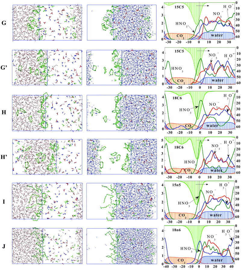 | ||
| Fig. 6 The 18 nitric “acid”/12 ether mixed systems (G–J)
(see Table 1 and Fig. 4 for definitions) where “acid”=(HNO3, NO3−, H3O+). | ||
For acidic systems G and H containing 18C6 and 15C5 ethers, we decided to investigate the role of pressure P on the distribution of the different species. Due to the high fluctuations of P during the simulations, the latter were performed at constant volume, which was isotropically scaled down by 9% and 7%, respectively, leading to the systems noted G′ and H′. It can be seen from Table 2, Table S1† and Fig. 6 that this volume reduction has little influence on the interfacial concentrations, confirming the accumulation of ethers and of HNO3 species at the interface.
Demixing simulations of systems G and H (Fig. 7) also confirm the above conclusions. At the beginning (0 ps), the aqueous and CO2 phases and the solutes (crown ethers and acid) are “perfectly mixed”. During the dynamics, the phases separate very rapidly (in less than 0.5 ns), leading to two interfaces. The final CO2 phase is quasi-“dry” and the aqueous phase contains a few CO2 molecules. All 18C6 or 15C5 crowns adsorb about equally onto the two interfaces, as does the majority of neutral HNO3 molecules, while the H3O+ and NO3− ions sit in water.
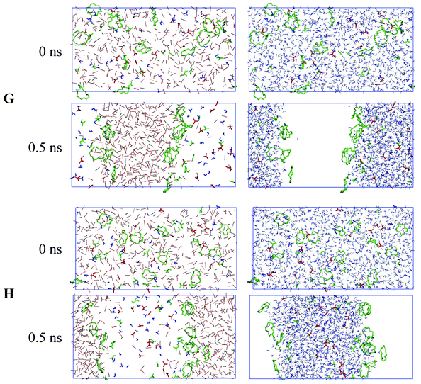 | ||
| Fig. 7 Demixing simulations of “perfectly mixed” systems G and H: snapshots at 0 ns and after 0.5 ns with CO2 (left column) and water (right column) shown separately instead of superimposed for clarity. | ||
Discussion and conclusions
Molecular dynamics simulations at prebuilt interfaces and mixing–demixing simulations show that the aqueous and CO2 “liquids” do not mix and form, at the microscopic level, well defined phases linked by a narrow fluctuating interfacial region. All ethers studied are highly surface active and concentrate at the interface. There is no noticeable difference between their interfacial behavior, which suggests that their ion extracting properties should mainly be determined by their complementarity and specific interactions with the ion to be complexed. This is consistent with experimental observations.26,50As mentioned in the Introduction, there are, to our knowledge, no experimental data dealing with the interfacial properties of the studied extraction systems. However, surface activity of ethers is consistent with the results of similar simulations at a water/chloroform interface, which bears obvious analogies with the water/CO2 interface.29 They are also consistent with the observed surface activity of ethers and crown ethers at liquid/liquid and water/air interfaces.51 The main difference comes from the higher temperature and pressure, leading to larger diffusion of all species. As a result, the lifetime of weakly associated systems (e.g. via hydrogen bonding interactions) is much shorter with SC-CO2. We did not systematically study the effect of concentration. In the case of 18C6, it is seen that increasing its concentration does not lead to further accumulation at the interface, but to migration to the CO2 phase and adsorption to the second interface, confirming therefore the importance of interfacial activity. It will be interesting to investigate what happens at still higher concentrations, where new phenomena such as third phase formation may occur, as simulated recently with TBP (tri-n-butylphosphate).52
Acidic systems, modeled by an equimolar mixture of neutral and ionic forms of nitric acid for simplicity, display the main features of individual components, i.e. a peak of concentration at the interface for all ethers, as well as for the neutral form HNO3 of the acid. It is thus expected that other acids bearing bulkier and more hydrophobic substituents (carboxylic, sulfonic, phosphonic) should similarly concentrate at the interface in their neutral form as well as in their deprotonated form which displays the key features of amphiphilic molecules (a polar head flanked by an hydrophobic tail). These questions are being studied in our group, in relation with the ion extraction process and analysis of synergistic effects. An important issue concerns the possible evolution of the systems from well separated microphases and interfaces, to local microemulsions or micellar type supramolecular arrangements.20,22
Simulations on the K+ complex of 18C6 leads to decomplexation, and accumulation of the crowns at the interface, while all anions migrate in water, forming columnar type π-stacked arrangements. Thus, assisted K+ extraction to CO2 cannot proceed. On the other hand, when the complexes are constrained to remain inclusive, be the anions free to move or constrained to coordinate K+, they all remain at the interface, which strongly hints at an interfacial complexation mechanism. The reality likely corresponds to an equilibrium between complexed and uncomplexed ligands at the interface. According to our simulations, the complexes are trapped at the interface, which raises the question of the driving force for desorption from the interface and migration to CO2. Extraction may result from a reduction of interfacial area (e.g. upon collapse of water-in-CO2 or CO2-in-water droptlets) as well as by saturation of the interface, e.g. by using an excess of extractant molecules, or amphiphilic counterions or synergistic agents. As seen from our analysis, hydration of the Pic− counterions makes the complexes still too hydrophilic to migrate to the CO2 phase. Efficient counterions should be more hydrophobic than Pic−, while being hard enough to coordinate the complexed cation (e.g. on the face of the crown ether complexes). This feature is fully consistent with the experimental observation of enhanced extraction of aqueous metal ions by 18C6, 15C5 or DC18C6 in the presence of added pentadecafluorooctanoic acid.26 Extraction of K+ and Na+ by glymes50 and of Sr2+ by DC18C616 similarly proceeds upon addition of an excess of perfluorinated octanoic or sulfonic acids. At the interface, such amphiphilic counterions may create a negative potential and attract the “hard” cations which would be otherwise “repelled” by the interface.53
The present work is in many respects exploratory, and should be pursued along several directions. For instance, testing the role of potential energy representation of the system, including polarization and non-additivity effects.54 Concerning the sampling of the systems, we feel that it is sufficient, as seen by the major reorganization that takes place in some cases, and by mixing–demixing computer experiments on these systems55 and others.31,32,56 Other questions concern the effect of temperature, of size of the systems and interfacial area, as well as more accurately describing acidity effects. We however believe that the main conclusion, i.e. the interfacial activity of the studied polyether molecules and their complexes, and of the neutral form of nitric acid does not stem from computational artefacts. The simulations should stimulate further experimental studies on the importance and precise description of interfacial phenomena in assisted ion extraction to supercritical weakly polar phases. The studied systems have also many analogies with those involving the liquid–liquid extraction of hard cations (e.g. alkaline earth, trivalent lanthanides, actinides) by PEG (polyethylene glycols).57–61
Acknowledgements
The authors are grateful to IDRIS, CINES and Université Louis Pasteur for computer resources and to PRACTIS for support. E. Engler is acknowledged for software developments. PV thanks the French Ministry of Research for a grant and WG thanks Prof. C. Wai and A. Rustenholtz for stimulating discussions.References
- H. Watarai, Trends Anal. Chem., 1993, 12, 313 CrossRef CAS.
- P. R. Danesi, in Principles and Practices of Solvent Extraction, ed. J. Rydberg, C. Musikas and G. R. Choppin, M. Dekker, Inc., New York, 1992, p. 157 Search PubMed.
- H. H. Girault and D. J. Schiffrin, in Electroanalytical Chemistry, ed. A. J. Bard, Dekker, New York, 1989, p. 1 Search PubMed.
- J. D. Lamb, J. J. Christensen, J. L. Oscarson, B. L. Nielsen, B. W. Asay and R. M. Izatt, J. Am. Chem. Soc., 1980, 102, 6820 CrossRef CAS.
- J. P. Behr, M. Kirch and J.-M. Lehn, J. Am. Chem. Soc., 1985, 107, 241 CrossRef CAS.
- F. Berny, N. Muzet, L. Troxler and G. Wipff, in Supramolecular Science: where it is and where it is going, ed. R. Ungaro and E. Dalcanale, Kluwer Academic Publishers, Dordrecht, 1999, p. 95 Search PubMed.
- M. Baaden, F. Berny and G. Wipff, J. Mol. Liq., 2001, 90, 3 CrossRef.
- I. Benjamin, Acc. Chem. Res., 1995, 28, 233 CrossRef CAS.
- E. Stoyanov, I. Smirnov, A. Varnek and G. Wipff, in Euradwaste 1999: Radioactive Waste Management Strategies and Issues, ed. C. Davies, European Commission, Brussels, 2000, p. 519 Search PubMed.
- C. M. Wai and S. Wang, J. Chromatogr. A, 1997, 785, 369 CrossRef CAS.
- C. Erkey, J. Supercrit. Fluids, 2000, 17, 259 CrossRef CAS.
- N. G. Smart, T. Carleson, T. Kast, A. A. Clifford, M. D. Burford and C. M. Wai, Talanta, 1997, 44, 137 CrossRef CAS.
- K. E. Laintz, C. M. Wai, C. R. Yonker and R. D. Smith, Anal. Chem., 1992, 64, 2875 CrossRef CAS.
- V. Babain, A. Murzin, A. Shadrin and N. Smart, 5th Meeting on Supercritical Fluids, 1998, 155 Search PubMed.
- M. Ashraf-Khorassani, M. T. Combs and L. T. Taylor, J. Chromatogr. A, 1997, 774, 37 CrossRef CAS.
- C. M. Wai, Y. Kulyako, H.-K. Yak, X. Chen and S.-J. Lee, Chem. Commun., 1999, 2533 RSC.
- Y. Lin, C. M. Wai, F. M. Jean and R. D. Brauer, Environ. Sci. Technol., 1994, 28, 1190 CAS.
- R. Schurhammer, F. Berny and G. Wipff, Phys. Chem. Chem. Phys., 2001, 3, 647 RSC.
- R. Schurhammer and G. Wipff, New J. Chem., 2002, 26, 229 RSC.
- M. Baaden, R. Schurhammer and G. Wipff, J. Phys. Chem. B, 2002, 106, 434 CrossRef CAS.
- S. R. P. da Rocha, K. P. Johnston, R. E. Westacott and P. J. Rossky, J. Phys. Chem. B, 2001, 105, 12092 CAS.
- S. Salaniwal, S. T. Cui, P. T. Cummings and H. D. Cochran, Langmuir, 1999, 15, 5188 CrossRef CAS.
- S. Salaniwal, S. T. Cui, H. D. Cochran and P. T. Cummings, Langmuir, 2001, 17, 1773 CrossRef CAS.
- J. M. Lehn, in Physical Chemistry of Transmembrane Ion Motions, ed. G. Spach, Elsevier, Amsterdam, 1983, p. 181 Search PubMed.
- H. C. Visser, D. N. Reinhoudt and F. de Jong, Chem. Soc. Rev., 1994, 75 RSC.
- S. Mochizuki, N. Wada, R. L. Smith and H. Inomata, Analyst, 1999, 124, 1507 RSC.
- G. Wipff and L. Troxler, in Computational Approaches in Supramolecular Chemistry, ed. G. Wipff, Kluwer, Dordrecht, 1994, p. 319 Search PubMed.
- P. C. Junk, Rev. Inorg. Chem., 2001, 21, 93 Search PubMed.
- L. Troxler and G. Wipff, Anal. Sci., 1998, 14, 43 Search PubMed.
- M. Lauterbach, E. Engler, N. Muzet, L. Troxler and G. Wipff, J. Phys. Chem. B, 1998, 102, 225 CrossRef CAS; N. Muzet, E. Engler and G. Wipff, J. Phys. Chem. B, 1998, 102, 10772 CrossRef CAS.
- M. Baaden, F. Berny, N. Muzet, R. Schurhammer, L. Troxler and G. Wipff, in Euradwaste 1999: Radioactive Waste Management Strategies and Issues, ed. C. Davies, European Commission, Brussels, 2000, p. 519 Search PubMed.
- D. A. Case, D. A. Pearlman, J. C. Caldwell, T. E. Cheatham III, W. S. Ross, C. L. Simmerling, T. A. Darden, K. M. Merz, R. V. Stanton, A. L. Cheng, J. J. Vincent, M. Crowley, D. M. Ferguson, R. J. Radmer, G. L. Seibel, U. C. Singh, P. K. Weiner and P. A. Kollman, AMBER5, University of California, San Francisco, 1997 Search PubMed.
- A. E. Howard, U. C. Singh, M. Billeter and P. A. Kollman, J. Am. Chem. Soc., 1988, 110, 6984 CrossRef CAS.
- L. Troxler, J. M. Harrowfield and G. Wipff, J. Phys. Chem. A, 1998, 102, 6821 CrossRef CAS.
- J. Åqvist, J. Phys. Chem., 1990, 94, 8021 CrossRef.
- W. L. Jorgensen, J. Chandrasekhar, J. D. Madura, R. W. Impey and M. L. Klein, J. Chem. Phys., 1983, 79, 926 CrossRef CAS.
- C. S. Murthy, K. Singer and I. R. McDonald, Mol. Phys., 1981, 44, 135 CAS.
- I. G. Tironi, R. Sperb, P. E. Smith and W. F. van Gunsteren, J. Chem. Phys., 1995, 102, 5451 CrossRef CAS.
- G. Wipff, E. Engler, P. Guilbaud, M. Lauterbach, L. Troxler and A. Varnek, New J. Chem., 1996, 20, 403 Search PubMed.
- B. F. Graham, A. F. Lagalante, T. J. Bruno, J. M. Harrowfield and R. D. Trengove, Fluid Phase Equilib., 1998, 150–151, 829 CrossRef.
- H. J. C. Berendsen, J. P. M. Postma, W. F. van Gunsteren and A. DiNola, J. Chem. Phys., 1984, 81, 3684 CrossRef CAS.
- M. Lauterbach, E. Engler, N. Muzet, L. Troxler and G. Wipff, J. Phys. Chem. B, 1998, 102, 225 CrossRef CAS.
- K. Jackson, L. E. Bowman and J. L. Fulton, Anal. Chem., 1995, 67, 2368 CrossRef CAS.
- K. Harrison, J. Goveas, K. P. Johnston and E. A. O'Rear, Langmuir, 1994, 10, 3536 CrossRef CAS.
- G. Ranghino, S. Romano, J. M. Lehn and G. Wipff, J. Am. Chem. Soc., 1985, 107, 7873 CrossRef CAS.
- R. Schurhammer, PhD Thesis, Université Louis Pasteur de Strasbourg, 2001.
- P. Maverick, P. Seiler, B. Schweitzer and J. D. Dunitz, Acta Crystallogr., Sect. B, 1980, 36, 615 CrossRef.
- M. Dobler, Ionophores and their Structures, Wiley Interscience, New York, 1981 Search PubMed.
- J. C. Barnes and J. C. Collard, Acta Crystallogr., Sect. C, 1988, 44, 565 CrossRef.
- S. Mochizuki, R. L. S. Jr and H. Inomata, Chem. Commun., 2000, 1381 RSC.
- B. A. Moyer, in Molecular Recognition: Receptors for Cationic Guests, ed. J. L. Atwood, J. E. D. Davies, D. D. McNicol, F. Vögtle and J.-M. Lehn, Pergamon, New York, 1996, p. 325 Search PubMed.
- M. Baaden, M. Burgard and G. Wipff, J. Phys. Chem. B, 2001, 105, 11131 CrossRef CAS.
- F. Berny, R. Schurhammer and G. Wipff, Inorg. Chim. Acta; Special Issue, 2000, 300–302, 384 Search PubMed.
- T. M. Chang and L. X. Dang, J. Chem. Phys., 1995, 104, 6772 CrossRef CAS.
- P. Vayssiere, PhD Thesis, in preparation.
- M. Baaden, F. Berny, N. Muzet, L. Troxler and G. Wipff, in Calixarenes for Separation. ACS Symposium Series 757, ed. G. Lumetta, R. Rogers and A. Gopalan, ACS, Washington DC, 2000, p. 71 Search PubMed.
- R. D. Rogers, A. H. Bond, C. B. Bauer, J. Zhang and S. T. Griffin, J. Chromatogr. B, 1996, 680, 221 CrossRef CAS.
- C. S. Pawaskar, P. K. Mohapatra and V. K. Manchanda, J. Radioanal. Nucl. Chem., 1999, 242, 627 CAS.
- K. V. Lohithakshan, P. D. Mithapara, S. A. Pai and S. K. Aggarwal, Radiochim. Acta, 1998, 81, 17 Search PubMed.
- S. A. Pai, K. V. Lohithakshan, P. D. Mithapara and S. K. Aggarwal, Radiochim. Acta, 1998, 81, 67 Search PubMed.
- A. M. Y. Jaber and A.-E. Al-Naser, Talanta, 1997, 44, 1719 CrossRef CAS.
Footnote |
| † Electronic supplementary information (ESI) available: Average solute–solvent interaction energies per molecule from the last 200 ps (kcal mol−1). See http://www.rsc.org/suppdata/cp/b2/b208989k/ |
| This journal is © the Owner Societies 2003 |