Droplet formation in a microchannel network†
Takasi
Nisisako
*,
Toru
Torii
and
Toshiro
Higuchi
Department of Precision Engineering, School of Engineering, The University of Tokyo, 7-3-1, Hongo, Bunkyo-ku, Tokyo 113-8656, Japan
First published on 18th January 2002
Abstract
A method is given for generating droplets in a microchannel network. With oil as the continuous phase and water as the dispersed phase, pico/nanoliter-sized water droplets can be generated in a continuous phase flow at a T-junction. The channel for the dispersed phase is 100 μm wide and 100 μm deep, whereas the channel for the continuous phase is 500 μm wide and 100 μm deep. For given experimental parameters, regular-sized droplets are reproducibly formed at a uniform speed. The diameter of these droplets is controllable in the range from 100–380 μm as the flow velocity of the continuous phase is varied from 0.01 m s−1 to 0.15 m s−1.
Introduction
The past decade has seen increased interest in chemical reactions in microfabricated devices. Analysis of reactions in these devices demands technique for handling small amount of liquids, such as metering, transportation and mixing. Recently, chemical and biochemical experiments have been reported using pico/nanoliter-sized droplets.1–3 Treating liquid samples in droplet shape has the advantage that dead volume can be decreased. Therefore, a droplet-based chemical reactor is attractive, and preparation of droplets in a microchannel is likely to become increasingly important.One of the promising schemes for formation and manipulation of droplets is pneumatic handling.4 Liquid samples are metered, transported and mixed in air-segmented shape using pneumatic pressure. However, preventing evaporation of liquid samples is not easy and the decrease of liquid samples will be critical when handling smaller volumes of droplets.
Piezoelectric droplet generation has been popular as one of the key technologies of ink jet printers, and has been applied to dispensing liquid samples.5 Although small amounts of droplets can be formed reproducibly, ejected droplet size is not changed widely.
A technique for emulsification using a microchannel device has recently been reported.6 Regular-sized emulsion cells are generated by permeating a dispersed phase into a continuous phase through a silicon microchannel. In this method the droplet size depends on the microchannel structure and cannot be varied. Consequently, it is not suitable for metering variable volumes of chemical samples.
We propose here a novel method for generating water-in-oil droplets in a microchannel network. The design of microchannel is simple and no electrical device is integrated. As the water droplets are surrounded by oil phase, they are free from any evaporation problem. Our method is applicable to the preparation of chemical samples and emulsification processes. This method of droplet formation is shown schematically in Fig. 1.
 | ||
| Fig. 1 Schematic of the microchannel (left) and principle of droplet formation at a T-junction (right). | ||
Experimental
Microchannel fabrication
A T-junction structure was fabricated on a plate of polymethyl methacrylate (PMMA) using a 100 μm diameter end mill. The channel surface must be hydrophobic naturally. Each channel has a depth of 100 μm. The width of the narrower channel for the dispersed phase is 100 μm, and that for continuous phase flow is 500 μm. The channels to the pressure sensors are 100 μm in width. The surface roughness (Ra) of the channel is less than 1.0 μm. The cross section of the channels is rectangular (Fig. 2). The channel length for the continuous phase is 15 mm and for the dispersed phase is 5 mm. A T-junction component is positioned 10 mm from a supply port of the continuous phase flow. A deeper and wider region (depth 1 mm, width 2 mm) is made as a reservoir for observing the droplet size in the spherical shape. Adhesive tape (thickness: 23 μm) is used to enclose these channels.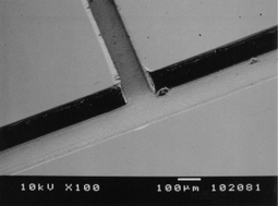 | ||
| Fig. 2 SEM image of top view of the micro-channels fabricated on a PMMA plate. | ||
Equipment and procedures
Syringe pumps (KDS100; Kd Scientific) are employed for injection of the dispersed phase flow and continuous phase flow. Ultra-pure water is used as the dispersed phase and high oleic sunflower oil (triolein, 80%) as the continuous phase. Both are injected using syringe pumps. No surfactant is added to either phase.Semi-conductor pressure sensors (PMS-5M; Toyoda Machine Works, Japan) are set in the plate to study the conditions for droplet formation and to confirm that the flow rate is constant. Droplet formation at the T-junction is observed using a microscope (BX50; Olympus, Japan) and a high-speed video camera (FASTCAM-ultima; Photoron, Japan). 4500 gray-scale images can be recorded at full frame size (height 256 pixels, width 256 pixels) for 1 second. The droplet size is measured by counting pixels.
Results and discussion
Regular-sized droplets of water in oil were generated at the T-junction (Fig. 3). From the recorded pictures, detachment of water droplets from the channel wall is seen to be important for getting smaller droplets, and apparently, the hydrophobic property of the channel surface has a favorable effect on it. The droplet size was controlled by changing the continuous phase (oil) flow rate and the dispersed phase (water) flow rate. As the continuous phase flow rate increased the diameter of the droplet decreased. Droplet production rate was measured when the diameter of droplets was 100 μm. A linear relation was found between oil pressure and water pressure (Fig. 4). The rate of production is estimated to be proportional to the square of the oil pressure (Fig. 5). | ||
| Fig. 3 Droplet formation at the T-junction (image by the high-speed video camera). | ||
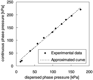 | ||
| Fig. 4 Water pressure versus oil pressure when the diameter of water droplets is approximately 100 μm. | ||
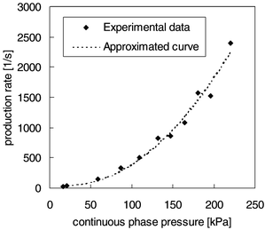 | ||
| Fig. 5 Effect of continuous phase (oil) pressure on droplet production rate. | ||
Effect of continuous phase flow velocity on droplet size
Fig. 6 shows data from droplet size measurements. For a given flow rate of the dispersed phase (water), the droplet size decreased as the continuous phase flow velocity increased, and the diameter of droplets reached approximately 100 μm at 0.15 m s−1. The droplet size starts to decrease linearly at around 0.05 m s−1 with increasing continuous phase flow velocity. This indicates that the fluidic behavior at the T-junction changes around that point. It is expected that much smaller droplets (20–30 μm in diameter, for example) will be generated at a higher velocity of continuous phase flow, but because of the pressure at a higher flow velocity, deformation of enclosure and adhesive force have to be considered and improved.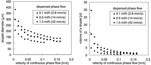 | ||
| Fig. 6 Effect of velocity of continuous phase flow on droplet size (left: droplet diameter data, right: volume of a droplet calculated from the diameter). | ||
Effect of continuous phase flow velocity on droplet production rate
Fig. 7 shows the droplet production rate as a function of the velocity of the continuous phase. Production rate is likely to increase linearly. This result is considered to be reasonable, taking into account that the flow rate of the dispersed phase is constant and that generated droplets have almost the same volume when the flow velocity of the continuous phase is more than 0.05 m s−1 (Fig. 6, right).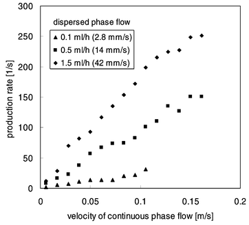 | ||
| Fig. 7 Effect of velocity of continuous phase flow on droplet production rate. | ||
Conclusion
A novel method has been presented for generating water-in-oil droplets at a T-junction in a microchannel network. The droplet size can be controlled: the minimum diameter of the droplets was about 100 μm, and the maximum 380 μm, as the flow velocity of the continuous phase was changed from 0.01 to 0.15 m s−1. The droplet production rate can also be changed. Refinement of this technique will allow the production of oil-in-water droplets and also microcapsules in microfabricated devices. This method is applicable not only to liquid metering but also to emulsification and drug delivery systems (DDS), for example.In order to use these generated droplets as small reaction/analysis chambers, a manipulation method is essential. In another project, we are working on electrostatic manipulation of droplets in liquid;7 it will be combined with this droplet preparation method in the near future.
References
- M. Washizu, IEEE Trans. Ind. Appl., 1998, 34(4), 732–737 CrossRef CAS.
- A. Torkkeli, A. Häärä, J. Saarilahti, H. Härmä, T. Soukka and P. Tolonen, Droplet Manipulation on a Superhydrophobic Surface for Microchemical Analysis, Proceedings of the Transducers′01 Eurosensors XV Conference, International Conference on Solid-State Sensors and Actuators, Munich, Germany, 2001, 1150–1153 Search PubMed.
- J. Vykoukal Jon A. Schwartz Frederick F. Becker and Peter R. C. Gascoyne, A Programmable Dielectrophoretic Fluid Processor for Droplet-based Chemistry,Proceedings of Micro Total Analysis Systems ′01, Monterey, CA, USA, 2001, pp. 72–74 Search PubMed.
- K. Hosokawa T. Fujii and I. Endo, Hydrophobic Microcapillary Vent for Pneumatic Manipulation of Liquid in μTAS,, Proceedings of Micro Electro Mechanical Systems ′98, Banff, Canada, 1998, 307–310 Search PubMed.
- S. Ekström, D. Ericsson, P. Önnerfjord, M. Bengtsson, J. Nilsson, G. Marko-Varga and T. Laurell, Anal. Chem., 2001, 73, 214–219 CrossRef CAS.
- T. Kawakatsu, Y. Kikuchi and M. Nakajima, J. Am. Oil Chem. Soc., 1997, 74(3), 317–321 CrossRef CAS.
- T. Taniguchi, T. Torii and T. Higuchi, Lab Chip, submitted for publication Search PubMed.
Footnote |
| † Presented at the International Symposium on Microchemistry and Microsystems (ISMM 2001), Kawasaki, Japan, September 16–18, 2001. |
| This journal is © The Royal Society of Chemistry 2002 |
