Structural characterisation of the highly deintercalated LixNi1.02O2 phases (with x ≤ 0.30)†
L. Croguennec*a, C. Pouillerieab, A. N. Mansourc and C. Delmasa
aInstitut de Chimie de la Matière
Condensée de Bordeaux-ICMCB-CNRS and Ecole Nationale Supérieure
de Chimie et Physique de Bordeaux, Av.
Dr A. Schweitzer, 33608, Pessac Cedex, France
bSAFT, 113 Bd Alfred Daney, 33 074, Bordeaux
Cedex, France
cNaval Surface Warfare Center, Carderock Division, 9500
MacArthur Boulevard, West Bethesda, MD 20817-5700, USA
First published on 10th October 2000
Abstract
The full structural characterisation of the highly deintercalated LixNi1.02O2 (x ≤ 0.30) phases has been performed. The structure of the Li0.30Ni1.02O2 phase was refined by the Rietveld method. The cationic distribution was found to be identical to that of the pristine material. A study of the Li//LixNi1.02O2 system at high potential has shown the successive formation of two phases with O3 (AB CA BC) and O1 (AB) oxygen packing, respectively, near the NiO2 composition. Since slab gliding is at the origin of the O3 to O1 transition, layer displacement faults were observed in these two phases. For the O3 phase, as soon as all the lithium ions are removed from an interslab space, an O1-type fault occurs locally. In contrast, for the O1 phase, the presence of extra-nickel ions in the interslab space prevents slab gliding in the vicinity and, therefore, O3-type interslab spaces remain in the O1-type packing. The X-ray diffraction patterns were simulated using the DIFFaX program. It was shown that the stabilisation of the O1-type packing at the very end of the deintercalation process is due to a minimisation of the interactions between the p orbitals of the oxygen ions through the van der Waals gap. A two-phase domain is observed between Li0.30NiO2 and a composition close to NiO2 since, for very low lithium contents, the Ni3+/Ni4+ ordering (and the lithium/vacancy ordering) is no longer possible and the difference in size between the cations leads to the formation of constraints which destabilise the Ni3+ ions in a lattice where Ni4+ ions prevail. At the end of the deintercalation process, the NiO2 compound appears to be highly covalent, therefore, the steric effects prevail over the electrostatic repulsion effects, as in chalcogenides.
Introduction
In the last few years, numerous studies have been devoted to the structural, physical and electrochemical characterisation of LiNiO21–6 which is, with LiCoO2 and LiMn2O4, a promising positive electrode for lithium-ion batteries. It is now well known that if too large an amount of lithium is deintercalated from the LixNiO2 material, the reversibility dramatically falls upon cycling. This has been attributed to the strong decrease of the interlayer distance for the LixNiO2 (x < 0.30) compositions.Up to now, the behaviour of LiNiO2 at high potential was not well understood. Therefore, we have performed a structural and electrochemical characterisation of the Li//LixNi1.02O2 system at high potential. The electrochemical study has been reported elsewhere7 and mainly shows the successive formation in the vicinity of the Ni1.02O2 composition of two phases, called R3 and H4 (for the rhombohedral 3rd deintercalated phase and the hexagonal 4th deintercalated phase, respectively). Very recently, Arai et al. published a similar study, in good agreement with our results.8 The presence of 7% extra nickel ions in the interslab space was shown to be sufficient to prevent the formation of the H4 phase. Lithium can be reversibly reintercalated in the Ni1.02O2 phase and good cyclability is obtained, but at low rate, for the Li//LixNi1.02O2 system over a large potential range. In this study, cycling at high potential also provides evidence for the inhomogeneity of the starting material at the crystallite level. Indeed, even if the Li0.98Ni1.02O2 material appears pure, it in fact corresponds to a mixture of various phases with very similar stoichiometries. The crystallites which are the closest to the ideal stoichiometry form an H4 phase which is stable at high potential, while those which present a larger departure from stoichiometry lead to an H4 phase which slowly transforms into a new phase, called R′3, through a Ni3+ migration from the slab to the interslab space.
Recently, the formation of the H4 phase (i.e. a hexagonal phase with the CdI2-type structure) at the end of the lithium deintercalation from the LixNiO2 system was announced.9 However, the structure described in this paper corresponds in fact to a rhombohedral phase (AB CA BC oxygen packing, O3-type structure). In the O3 structural type, the alkali cations (Li+) are located in octahedral (O) sites and there are three NiO2 slabs per unit cell.10 The studies performed by other authors do not show evidence for the formation of the H4 phase, probably either because the material was not deintercalated enough11 or because the starting compounds contained too much nickel on the lithium site.1,3,12
In this paper, the full structural characterisation of the highly deintercalated LixNi1.02O2 (x ≤ 0.30) phases is presented. The intention is to provide a better understanding of the Li//LixNi1.02O2 system at high potential. X-Ray absorption spectroscopy and X-ray diffraction were used to characterise the short and long range structure.
Experimental
The LixNi1.02O2 phases were obtained by electrochemical lithium deintercalation in lithium batteries with the following electrochemical chain: Li/1 M LiPF6 in a mixture of propylene carbonate (PC), ethylene carbonate (EC) and dimethyl carbonate (DMC) (1 ∶ 1 ∶ 3 by volume)/Lix − zNi1 + zO2 with carbon black as a conductive agent and poly(ethylene tetrafluoride) (PTFE) as binder. These cells were assembled in a glove box filled with argon and were charged at low rate (C/200) in galvanostatic mode using a home made system monitored by a HP1000 computer.13 The C rate is defined here as the exchange of 1 electron in 1 h. The delithiated positive electrodes were recovered in a glove box, washed in DMC in order to remove the remaining LiPF6 salt and dried under vacuum.The X-ray absorption spectroscopy (XAS) experiments were performed on beamline X-11A at NSLS with the electron storage ring operating at an electron energy of 2.8 GeV and stored current in the range of 110 to 250 mA. Spectra of the Ni K-edge (8333 eV) were recorded in the transmission mode at room temperature (300 K) using a variable exit double-crystal monochromator with two flat Si(111) crystals. The XAS measurements were continuously collected in situ during the charge cycle, as already described elsewhere.14 The calibration in energy was done using a 4 µm thick nickel foil as reference. The compounds NiO and KNiIO6 were used as references for Ni(II) and Ni(IV).15
The X-ray diffraction (XRD) patterns were recorded with a Siemens D5000 diffractometer with Cu-Kα radiation (0.02° (2θ)/10 s in the 10–80° range). A sample holder which avoided any contact of the highly oxidised positive electrodes with air was used. The structure refinement of the Li0.30Ni1.02O2 phase (R2) was performed by the Rietveld method using the Fullprof program.16
For the most deintercalated phases, a Rietveld refinement of the structure was not possible due to the presence of structural defects. By analogy with other structures, or from ab initio calculations, structural models were proposed for the R3 and H4 phases. As a first step, the XRD patterns of the ideal structures were simulated using the Powdercell program.17 This program calculates the diffracted intensity versus the 2θ value for a given structure (space group, cell parameters, profile parameters and atomic positions are required). Then, the simulated XRD patterns of the actual structures (characterised by the presence of stacking faults) were obtained using the DIFFaX program, which calculates the diffracted intensity versus the 2θ value for a given stacking of layers.18 In this study, the slabs were built up with the same atomic positions as those used for the simulation of the ideal ordered structures. These slabs were then packed along the c direction with a translation vector, which possibly introduced the type of stacking faults. All the simulations considered a random distribution of stacking faults.
Results and discussion
As reported in a previous paper,7 the study of the Li//LixNi1.02O2 system at high potential has shown that the strong decrease of the interlayer distance for compositions such as x < 0.30 (the Li0.30Ni1.02O2 phase, called R2) results from the formation, in the vicinity of the Ni1.02O2 composition, of two phases called R3 and H4 (Fig. 1). Herein, the full structural characterisation of these three phases is reported.![Charge curve obtained
for a Li/LiPF6 PC, EC, DMC (1 ∶ 1 ∶ 3)/Li0.98Ni1.02O2 cell [in galvanostatic mode, at low rate (C/200)
and up to 4.7 V]. The various phases are associated with a letter which
gives the unit cell symmetry R (rhombohedral), M (monoclinic)
or H (hexagonal) and with a number which indicates the order of
appearance upon deintercalation.](/image/article/2001/JM/b003377o/b003377o-f1.gif) | ||
| Fig. 1 Charge curve obtained for a Li/LiPF6 PC, EC, DMC (1 ∶ 1 ∶ 3)/Li0.98Ni1.02O2 cell [in galvanostatic mode, at low rate (C/200) and up to 4.7 V]. The various phases are associated with a letter which gives the unit cell symmetry R (rhombohedral), M (monoclinic) or H (hexagonal) and with a number which indicates the order of appearance upon deintercalation. | ||
Because of the presence of structural defects, an X-ray absorption study was first carried out in order to obtain local structural data relevant for structural simulations.
X-ray absorption spectroscopy study
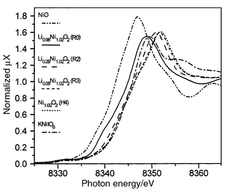 | ||
| Fig. 2 XANES spectra of the LixNi1.02O2 phases as a function of state of charge (Ni K-edge). | ||
Although at such high potential, oxidation of either nickel ions or oxygen anions must be considered, the XAS results show that the redox center at the end of the deintercalation process is still nickel.
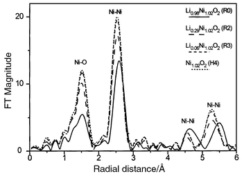 | ||
| Fig. 3 Phase-uncorrected Fourier transforms of k3-weighted EXAFS spectra of the LixNi1.02O2 phases as a function of state of charge (Ni K-edge). | ||
The EXAFS study over the complete composition range has already been reported elsewhere.19 In this paper, only the results required to complete the structural characterisation of the highly deintercalated LixNi1.02O2 phases (x ≤ 0.30) are given. The local structural parameters deduced from the quantitative analysis of the Fourier transforms for the R2, R3 and H4 phases are reported in Table 1.
| H4 | R3 | R2 | |||
|---|---|---|---|---|---|
| Ni1.02O2 | Liε′Ni1.02O2 | Li0.30Ni1.02O2 | |||
| Ni–O shell | N | 5.6(5) | 5.2(4) | 5.4(2) | 0.6(2) |
| d(Ni–O)/Å | 1.884(4) | 1.885(3) | 1.888(5) | 2.073(5) | |
| Average: 1.906(9) | |||||
| σ2 | 0.0030(6) | 0.0034(6) | 0.0039(6) | 0.0039(6) | |
| Ni–Ni shell | N | 5.5(4) | 5.5(3) | 5.5(3) | |
| d(Ni–Ni)/Å | 2.821(3) | 2.825(3) | 2.831(3) | ||
| σ2 | 0.0026(4) | 0.0031(3) | 0.0035(3) | ||
For nickel in the R3 and H4 phases, it appears that a regular coordination is observed with a Ni–O distance of 1.884 Å, a value close to the sum of the ionic radii of the Ni4+ and O2− ions (1.88 Å) and consistent with the presence of nickel at an oxidation state of about 4+.
As for more lithiated phases (Li0.63Ni1.02O2 and Li0.98Ni1.02O2), the refinement of the first shell of R2 (Li0.30Ni1.02O2) requires consideration of the existence of two different Ni–O bond lengths.20–24 The Ni–O distances can be understood by taking into account that Ni(III) has a distorted octahedral coordination with four oxygen neighbours at a distance of ca. 1.92 Å and two oxygen neighbours at a distance of ca. 2.08 Å, whereas Ni(IV) has an octahedral coordination with six oxygen neighbours at a distance of ca. 1.88 Å (as observed for the R3 and H4 phases). Therefore, the number of short and long Ni–O distances calculated for the R2 phase leads to a cationic distribution characterised by 0.71 Ni4+ and 0.31 Ni3+ ions, which is consistent with the expected oxidation state distribution (0.64 Ni4+ and 0.38 Ni3+) within the uncertainty of the data. The Ni–O and Ni–Ni distances decrease upon lithium deintercalation, in good agreement with the oxidation of Ni(III) to Ni(IV). The value of the Debye–Waller factor σ2, which includes both thermal motion and structural disorder, suggests a low disorder in the fully charged state and, therefore, a highly ordered structure for the NiO2 slabs. In fact, for the Li0.98Ni1.02O2 starting material, the Debye–Waller factors are 0.0044 and 0.0043 Å2 for the Ni–O and Ni–Ni distances, respectively.
X-Ray diffraction study
The R2 phase crystallises, like Li0.98Ni1.02O2,
in the trigonal symmetry [space group R![[3 with combining macron]](https://www.rsc.org/images/entities/char_0033_0304.gif) m, ahex = 2.8221(1), chex. = 14.404(1) Å].
The structural refinement by the Rietveld method was carried out assuming
an initial cationic distribution similar to that of the pristine phase, i.e.
(Li0.30Ni0.02□0.68)3b(Ni)3a. Refinement
of the isotropic displacement factors (B) is known to be
difficult from X-ray powder data, especially if the 2θ
range is small (10–80° in our experiments). For electrodes
recovered after an electrochemical experiment, it is even more difficult.
In this case, a preferential orientation of the crystallites is often observed,
which prevents an accurate determination of the isotropic atomic displacement
parameters (ADPs), since these two parameters are highly correlated.
As a first step, the ADPs were fixed to values commonly observed for lithium
nickelates: B(Ni) = 0.5, B(O) = 0.8
and B(Li) = 1.2 Å2.5 The results of the Rietveld refinement are reported
in Table 2. A comparison of the
experimental and calculated XRD patterns is shown in Fig. 4.
A good minimisation of the difference is obtained, emphasising the validity
of the structural model. In the final step, the ADPs were allowed to vary:
negative values were obtained with very large standard deviations, reflecting
the fact that too many structural parameters were refined for the amount of
information given by the XRD pattern.26
m, ahex = 2.8221(1), chex. = 14.404(1) Å].
The structural refinement by the Rietveld method was carried out assuming
an initial cationic distribution similar to that of the pristine phase, i.e.
(Li0.30Ni0.02□0.68)3b(Ni)3a. Refinement
of the isotropic displacement factors (B) is known to be
difficult from X-ray powder data, especially if the 2θ
range is small (10–80° in our experiments). For electrodes
recovered after an electrochemical experiment, it is even more difficult.
In this case, a preferential orientation of the crystallites is often observed,
which prevents an accurate determination of the isotropic atomic displacement
parameters (ADPs), since these two parameters are highly correlated.
As a first step, the ADPs were fixed to values commonly observed for lithium
nickelates: B(Ni) = 0.5, B(O) = 0.8
and B(Li) = 1.2 Å2.5 The results of the Rietveld refinement are reported
in Table 2. A comparison of the
experimental and calculated XRD patterns is shown in Fig. 4.
A good minimisation of the difference is obtained, emphasising the validity
of the structural model. In the final step, the ADPs were allowed to vary:
negative values were obtained with very large standard deviations, reflecting
the fact that too many structural parameters were refined for the amount of
information given by the XRD pattern.26
 | ||
| Fig. 4 Comparison of the calculated and experimental XRD patterns of the R2 phase. G and Al are associated with graphite and the aluminium sample holder, respectively. | ||
| Atom | Site | Wyckoff position | Biso/Å2 | Occupancy | ||
|---|---|---|---|---|---|---|
| x | y | z | ||||
| a Space group Rm, ahex = 2.8221(1), chex = 14.404(1) Å. Constraints: n(Li) = 0.30, n(Ni2) = 1, B(Li) = B(Ni1) = 1.2 Å2, B(Ni2) = 0.5 Å2, B(O) = 0.8 Å2.
Conventional Rietveld R-factors for points with Bragg contribution: Rwp = 13.2, RB = 6.26%. | ||||||
| Li | 3b | 0 | 0 | ½ | 1.2 | 0.30 |
| Ni1 | 3b | 0 | 0 | ½ | 1.2 | 0.024(2) |
| Ni2 | 3a | 0 | 0 | 0 | 0.5 | 1.00 |
| O | 6c | 0 | 0 | 0.2635(9) | 0.8 | 2.00 |
| Conditions of the run: | Profile parameters: | |||||
| T/K | 300 | Profile function | pseudo-Voigt | PV = ηL + (1 − η)G | ||
| Angular range/° | 10 ≤ 2θ ≤ 80 | η = η0 + X(2θ) | η0 = 0.34(6) | |||
| Step scan increment (2θ)/° | 0.02 | X = 0.003(2) | ||||
| Zero point (2θ) | −0.24(1) | Halfwidth parameters | U = 0.14(9) | |||
| No. fitted parameters | 14 | V = −0.05(6) | ||||
| W = 0.053(9) | ||||||
Nevertheless, it should be noted that the structural parameters (cell parameters, atomic positions and occupancy factor) are not modified by slight changes in the values of the isotropic ADPs. Only a slight modification of the scale factor and of the preferential orientation parameter was observed for different sets of ADPs. The amount of extra-nickel ions present in the interslab space was found to be the same as that of the starting material (2%), whatever the set of isotropic ADPs chosen. Up to the Li0.30Ni1.02O2 composition (R2 phase), the cationic distribution therefore appears unmodified.
The Ni–O bond length calculated from this refinement is equal to 1.915(6) Å, in good agreement with the expected Ni–O distance (1.910 Å), assuming that the Ni4+–O2− and Ni3+–O2− distances are equal to 1.88 and 1.96 Å, respectively, from the sum of the ionic radii.27 This bond length is also in good agreement with the average value (1.906 Å) found in the EXAFS study. Note also that the ahex parameter fits in well with the Ni–Ni distance deduced from the EXAFS study. The O–O distances between successive layers are 2.59 Å in the slabs and 3.24 Å in the interslab space, this difference emphasising the strong 2D character of the structure.
 | ||
| Fig. 5 Best XRD patterns obtained for the R3 (a, b) and H4 (c, d) phases. Absolutely pure phases were not obtained: the main diffraction lines of one pattern appear as small lines in the other. The high 2θ ranges (b and d) are enlarged along the y axis. G and ↓ denote peaks associated with graphite and the aluminium sample holder, respectively. | ||
2.1 The R3 phase. The XRD pattern given in Fig. 5a,b has been indexed in the hexagonal system. All the diffraction lines attributed to the R3 phase satisfy the rhombohedral condition (−h + k + l = 3n), their relative intensities are characteristic of the O3-type oxygen packing, as in pristine Li0.98Ni1.02O2. The hexagonal cell parameters are ahex = 2.8154(7) and chex = 13.363(6) Å, in rather good agreement with previously reported results, even though the value of chex is smaller by 0.1 Å than those previously reported.1,3,11,12Table 3 shows the good agreement between dobs and dcalc values.
m
space group)
| hkl | dobs/Å | dcalc/Å |
|---|---|---|
| 003 | 4.451 | 4.454 |
| 101 | 2.3985 | 2.3986 |
| 012 | 2.2899 | 2.2905 |
| 104 | 1.9709 | 1.9695 |
| 015 | 1.8014 | 1.8013 |
| 107 | 1.5035 | 1.5031 |
| 110 | 1.4076 | 1.4077 |
| 018 | 1.3777 | 1.3780 |
| 113 | 1.3421 | 1.3423 |
| 021 | 1.2141 | 1.2141 |
Considering the quality of the XRD pattern recorded for the R3 phase, a complete Rietveld analysis could not be done. In particular, the pseudo-Voigt function cannot take into account the abnormal broadening of the (01l) and (10l) Bragg reflections (Fig. 5a,b), as will be discussed in the following. Only the cell parameters were refined. However, in order to gain more insight into the R3 structure, simulation of the XRD pattern was performed with the nickel and oxygen ions in 3a (0, 0, 0) and 6c (0, 0, zox) positions, respectively. Several values of zox were tried. The best results were obtained with zox = 0.2625, which corresponds to a nickel–oxygen bond length of 1.88 Å (identical to that found in the EXAFS study). As shown in Fig. 6a, which gives a comparison of the experimental and simulated XRD patterns of the R3 phase, although all experimental diffraction lines are generated by the simulation, the intensity and the shape of the (10l) and (01l) diffraction lines are not well modelled. This discrepancy shows that the real structure of R3 is more complex. This point will be discussed hereafter.
 | ||
| Fig. 6 Comparison of the R3 experimental XRD pattern with that calculated for an ideal AB CA BC oxygen packing (a) and comparison of the H4 experimental XRD pattern with that calculated for an ideal AB oxygen packing (b). | ||
2.2 The H4 phase. The main diffraction lines of the H4 phase can be indexed with a hexagonal cell; a = 2.8145(6) and c = 4.346(2) Å. The remaining lines, which correspond to those of the R3 impurity phase, can be also indexed with a larger cell; a = 2.8145(6) and c = 13.039(5) Å. In this latter case, the rhombohedral condition is not satisfied. Therefore, a new structural type is expected and has to be characterised ab initio.
Integrated intensities were extracted from the XRD pattern by a full pattern
matching refinement (profile fitting procedure from the Fullprof program,
which does not require any structural model but only constrains the angular
position of the reflections to be consistent with the cell parameters).16 The profiles were described by means of a pseudo-Voigt
function. Since there is an anisotropic broadening of the diffraction lines,
it would have been better to model each peak individually in order to extract
more accurate values for the integrated intensities. However, the presence
of the R3 phase as an impurity requires a pattern decomposition program such
as Fullprof in order to take into account its contribution to the diffracted
intensities and to extract accurate integrated intensities for the H4 phase
from the best refinement. The integrated intensities were then converted into
structure factors (F) and used as input data for the Sirpow
program in order to solve the crystal structures from the powder data by direct
methods.28 The standard input file for this
program consists of lattice parameters (a = 2.8145
and c = 13.039 Å), space group (P3m1,
in agreement with the extinction conditions), chemical content of the
unit cell (at this step, only 3 Ni atoms are considered since Ni is the
dominant scatterer) and a file of reflections as provided by Fullprof
[(hkl), multiplicity, sin θ/λ,
2θ, F2]. Good results are obtained if
all the nickel ions are in the same position within the triangular lattice (C
for example). These positions are (0, 0, z) with z
equal to 0, 1/3 or 2/3 (the structure can thus be described in
the more symmetric Pm1 space group). Therefore,
each nickel ion must be surrounded by two oxygen layers in A and B positions
since the nickel ion can reasonably be expected to be in an octahedral site,
in agreement with the XAS results. Thus, two oxygen packings can be considered:
AB or AB AB BA.
The single-layered AB oxygen packing (O1-type structure), characteristic of CoO2, has already been observed for a number of transition metal binary compounds.12,29,30 In the O1 structural type, the remaining alkali cations (Li+) are located in octahedral (O) sites and there is one NiO2 slab within the unit cell.10 In agreement with a single-layered structure, the value of the c hexagonal parameter must be divided by three. Therefore, in this hypothesis, the cell parameters are a = 2.8145(6) and c = 4.346(2) Å. The nickel and oxygen ions are assumed to be, respectively, in the 1a (0, 0, 0) and 2d (1/3, 2/3, zox) sites. In this simulation, we have used zox = 0.217, which leads to dNi–O = 1.88 Å, in agreement with the EXAFS study. The simulated XRD pattern is compared in Fig. 6b with the experimental pattern. All the observed diffraction lines are simulated. Nevertheless, as for the R3 phase, a discrepancy in the intensity and width of the (10l) diffraction lines is observed showing that the real structure is more complex (see below).
It is also possible to simulate an XRD pattern in good agreement with the experimental pattern with a three-layered AB AB BA oxygen packing. In this hypothesis, the three nickel ions are in the 1a (0, 0, 0) and 2c (0, 0, 1/3) positions, the six oxygen ions are in the 2d (1/3, 2/3, zox) positions, with zox = 0.073, 0.2603, or 0.5937. As for the previous simulation, these positions were determined to obtain dNi–O = 1.88 Å. As in the previous case, a significant difference is observed for particular (hkl) lines between the width of the simulated and experimental patterns. Surprisingly, the patterns simulated for the AB and AB AB BA oxygen packings are very similar (Fig. 7). The only difference is the presence of the very weak (101), (102), (104) and (105) lines for the three-layered oxygen packing. It should be mentioned that these diffraction lines are the most intense ones for a structure with rhombohedral symmetry (like the R3 phase).
 | ||
| Fig. 7 Comparison of the H4 experimental XRD pattern with those calculated for AB oxygen packing and for three-layered AB AB BA oxygen packing. A perspective view of the two oxygen packings is also given. *: R3 impurity, G: graphite and ↓: sample holder. | ||
As already mentioned, although a great number of experiments were performed, a strictly pure H4 phase was never synthesised. The R3 phase always remains as an impurity. As a consequence, in the last structure hypothesis, it is not possible to attribute the lines observed at 2θ values of 37.5, 39.4, 46.5 and 51.3° (denoted by * in Fig. 7), either only to the R3 phase or to the R3 and H4 phases. Theoretically, if the H4 phase exhibited a three-layered structure, the (10l) and (01l) lines of R3 and H4 should be separated due to the difference between the chex cell parameters of the two phases (cR3 = 13.36 and cH4 = 13.04 Å). Nevertheless, the experimental lines are too broad and not intense enough to permit differentiation between one or two lines.
Comparison of the two hypotheses. A few arguments are against a three-layered structure for the H4 phase.
A transition upon lithium deintercalation from the AB CA BC oxygen packing of the R3 phase to the AB AB BA oxygen packing of the H4 phase would imply a complete rearrangement of the structure with bond breaking, since [NiO2] slab gliding is not sufficient to produce the transition. This reaction would be energy demanding and, therefore, probably not favoured. Nevertheless, it cannot be absolutely excluded from these considerations, since, in the case of the LixMoS2 system, the formation of LiMoS2 from MoS2 requires a complete rearrangement of the structure.31 In this case, the new MoS2 packing is maintained upon lithium deintercalation. In contrast, the LiNiO2 structure with AB CA BC oxygen packing is reversibly obtained upon lithium reintercalation in NiO2. Therefore, one can assume that the formation of the AB AB BA packing is unlikely for NiO2.
In contrast, the R3 rhombohedral structure and the CdI2-type structure are so intimately related, that the [NiO2] slabs of the R3 phase have only to glide with respect to each other to form the CdI2 stacking for the H4 phase. One out of every three layers glides from a (1/3a + 2/3b) vector while another glides from a (2/3a + 1/3b) vector.
In the AB AB BA oxygen packing, the oxygen anions from two consecutive [NiO2] slabs which form a trigonal prismatic site are closer to each other than those which form an octahedral site (2.44 instead of 2.93 Å) (Fig. 7). This short oxygen–oxygen distance leads to an increase of the electrostatic interactions between two adjacent slabs and to a destabilisation of the structure, if an oxygen → nickel electron transfer is not considered to decrease the charge borne by the oxygen anions. This 2.44 Å distance is too long to consider the formation of peroxide bonds but not long enough to completely exclude the formation of short contacts through the van der Waals gap. In the case of layered MX2 (X = S, Se or Te) chalcogenides, the van der Waals gap always consists of a layer of octahedra and tetrahedra sharing faces.32 Indeed, empty trigonal prismatic sites have never been reported in chalcogenides, although the strong covalent character of the M–X bonds in these materials decreases the electrostatic interactions. Therefore, we can assume that if the S, Se and Te anions are not able to stabilise such AB AB BA packing in chalcogenides, it is perfectly justified to question whether oxygen ions could do so in oxides. It should be noted that the hypothesis of covalent oxygen–oxygen bonds (peroxide bonds) along the height of the prism leads to intensities for the XRD pattern which are in complete disagreement with those obtained experimentally; the most intense being the (101), (102), (103), (104) and (105) lines.
The last point against AB AB BA oxygen packing for the H4 phase concerns the interslab distances. The Sirpow program tends to put the nickel ions at z = 0, 1/3 and 2/3, which is not expected if different packings (empty trigonal prisms or empty octahedra) exist within the van der Waals gap. Indeed, the zNi positions should be independent.
Even if the X-ray diffraction study does not allow differentiation between the AB and AB AB BA structural hypotheses for the hexagonal H4 phase, all the previous points permit us to make the assumption that the H4 NiO2 phase exhibits the CdI2-type structure. These results are in good agreement with the phase diagram obtained from first principles calculations by Van der Ven and co-workers for the Li//LixCoO2 system.33,34 They have shown that the expected stacking for the structure at the end of the lithium deintercalation is CdI2-type. Nevertheless, Fig. 7 shows how it is necessary to be careful when a structural model is proposed on the basis of powder X-ray diffraction data only.
Stacking faults. Recently, it has been shown in our laboratory that stacking faults (deformation and growth faults) in nickel hydroxides could explain the apparently abnormal broadening of the (10l) diffraction lines. Moreover, by increasing the amount of deformation faults, it is possible from AB oxygen packing [Ni(OH)2-type structure] to obtain AB CA BC packing (LiNiO2-type structure).35–37 A similar approach can be used to explain the structural transition between the R3 and H4 phases and the experimental diffraction patterns of the real materials. As shown in Fig. 5, the abnormal broadening of some diffraction lines of the R3 and H4 XRD patterns suggests that these phases do not exhibit the ideal CdCl2 and CdI2-type structures, respectively. Since slab gliding is at the origin of the R3 → H4 phase transition, it is not surprising that layer displacement faults (deformation faults) occur.
In a study of stacking faults in nickel hydroxide, it has been shown that the section of the structure along the (110) plane, currently used in the field of chalcogenides,29 allows one to visualise in a very convenient way the change of packing in the vicinity of the stacking faults. Fig. 8 presents sections of the structure of LixNiO2 phase (x ≈ 0):
— for the ideal R3 phase (AB CA BC oxygen packing)
— when two van der Waals gaps have been modified by a glide (the faulted oxygen layers are underlined):
 | (1) |
—when only two cfc-type van der Waals gaps remain within the structure:
 | (2) |
—for the ideal H4 phase (AB oxygen packing)
 | ||
| Fig. 8 Comparison of the structures of the R3 and H4 phases through a section along the (110) plane. | ||
In this description, the octahedra are represented by parallelograms (nickel in black, lithium hatched and vacancies in white) and the empty tetrahedra by triangles. An edge shared by two polyhedra belonging to the slab and the interslab space is represented by a point, while a face shared by two polyhedra is represented by a line. As clearly illustrated in Fig. 8, the octahedra share edges in the ideal R3 structure and faces in the ideal H4 structure.
As soon as all the lithium ions are locally removed from an interslab space, one can suppose that some [NiO2] slabs glide and that local AB packing occurs in R3 (O1-type stacking faults), even if the main packing is still AB CA BC (Fig. 8). In the same way, the presence of a few AB CA packing (O3-type stacking faults) in the AB packing (real H4 packing) is certainly related to the existence of structural defects and to the presence of extra-nickel ions in the interslab space, which are probably not statistically distributed within the structure. Interslab spaces without extra-nickel ions glide while those with a significant amount are maintained in the original packing (Fig. 8).
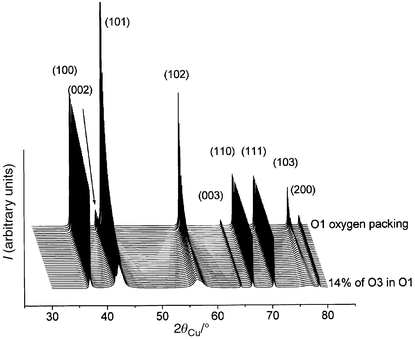
In order to check these hypotheses, XRD patterns were simulated using the DIFFaX program.18 As shown in Fig. 9, the introduction of an increasing amount of O1-type stacking faults in the O3 oxygen packing induces a significant broadening of the (10l) and (01l) diffraction lines, as experimentally observed in Fig. 5a,b, while, for instance, the (110) and (113) lines remain unchanged. The introduction of 5% of O1-type stacking faults in the O3 oxygen packing is sufficient to simulate the R3 experimental XRD pattern quite satisfactorily (Fig. 10a). In Fig. 11, we show the XRD patterns simulated in the presence of an increasing amount of O3-type stacking faults in the O1 stacking. Only the shape of the (10l) diffraction lines is affected. The introduction of 3% of O3-type stacking faults in the O1 oxygen packing leads to quite good agreement between the calculated and the experimental patterns for the H4 phase (Fig. 10b).
 | ||
| Fig. 9 XRD patterns simulated in the presence of an increasing amount of AB stacking faults in the AB CA BC oxygen packing. | ||
 | ||
| Fig. 10 Comparison of the R3 experimental XRD pattern with that calculated for 5% of AB stacking faults in the AB CA BC oxygen packing (a) and comparison of the H4 experimental XRD pattern with that calculated for 3% of AB CA stacking faults in the AB oxygen packing (b). | ||
 | ||
| Fig. 11 XRD patterns simulated in the presence of an increasing amount of AB CA stacking faults in the AB oxygen packing. | ||
Recently, from first principles calculations, Van der Ven and co-workers have shown that, for the Li0.15CoO2 composition, a new hybrid packing (H1–3) was expected.33,34 This hypothetical structure consists of alternate packing of O3 and O1-type interslab spaces. The faulted structures described above are also a mixing of O3 and O1-type environments but, contrary to H1–3 packing, with a statistical distribution of O1 and O3 blocks and with only a few O3 blocks in the O1 packing or vice versa (Fig. 8).
General discussion
Stability of the single-layered structure for the Ni1.02O2 compound
Fig. 12 shows the first charge/discharge cycle obtained for the Li//LixNi1.02O2 system, at low rate in potentiostatic mode, and the corresponding integrated curve. As shown by the integrated curve, the Li//LixNi1.02O2 system appears reversible over the 0 ≤ x ≤ 0.98 composition range. The presence of the peak associated with the R3 (H4) → R2 transition in the discharge profile emphasises the reversibility of the overall process. As soon as ε lithium ions are reintercalated in the host structure, the O1 stacking becomes unstable and is converted into O3.7 It is intuitively well understood that the lithium ions prefer the octahedral sites of the O3 structure to those of the O1 structure because, in this packing, they share faces with the NiO6 octahedra, while they share only edges in the O3 structure. Electrostatic repulsions are lower in this stacking and stabilise it versus the O1 type. This structural change was observed in CoO212 and is also evidenced by the theoretical calculation performed by Van der Ven and co-workers33,34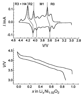 | ||
| Fig. 12 Charge/discharge cycle at low rate in potentiostatic mode for a Li//LixNi1.02O2 cell and the corresponding integrated curve (10 mV, 4 h between 3 and 4.45 V with 70 h floating at 4.45 V). | ||
Now the following question arises: why is the O3-type structure converted into the O1 type at the end of the lithium deintercalation? A 40 meV difference in energy between the two varieties has been calculated in the case of CoO2 by Van der Ven and co-workers from first principles calculations.33,34 The O1-type structure was previously reported to be stabilised versus the O3 type because of a maximisation of the distances between anions and, thus, a minimisation of the electrostatic repulsions.12 In fact, both ideal structures show similar distances between anions as they are both hexagonal close-packed oxygen structures. Comparison of electrostatic interactions in a pure ionic model shows that, even for the NiO2 composition, the O3-type structure would be more stable than the O1 type,38 resulting from the fact that there is a direct interaction between the nickel ions from two adjacent slabs in the O1-type packing. For the NiO2 composition, the pure ionic model is not relevant, since there is a strong covalency of the Ni–O bonds in the real material. Therefore, as there are no cations to screen the electrostatic repulsions between the anions of two consecutive slabs; one has to compare the spatial distribution of the orbitals in the van der Waals gap in order to explore the driving force for the R3 → H4 transition. If one considers a slab with, for example, the oxygen anions in the A and B positions of the triangular lattice and, therefore, the nickel cation in the C position, the oxygen p orbitals are engaged in σ bonds with the dx2 − y2 and dz2 nickel orbitals in order to form the NiO6 octahedra. These p orbitals point towards the six corners of an octahedron which has the oxygen atom in its center. Therefore, the p orbitals of the A and B oxygen anions point on the one hand toward the C position (nickel cation) in the slab and on the other hand toward the B and A positions in the van der Waals gap, respectively.
To illustrate the difference in interactions between these orbitals through the van der Waals gap in the two types of packing, it is convenient to use, as for the stacking faults description (Fig. 8), a section of the structure along the (110) plane (Fig. 13).
 | ||
| Fig. 13 Difference in interactions between the p oxygen orbitals through the van der Waals gap in the AB and AB CA BC packings illustrated by a section of the structure along the (110) plane (a and b, respectively). | ||
For an O3-type structure (AB CA BC packing), the oxygen p orbitals from both sides of the van der Waals gap point toward the same position of the triangular lattice, for example A, if the oxygen layers are in the B and C positions (Fig. 13a). This means a direct repulsive interaction between the two orbitals through an empty octahedral site of the interslab space which destabilises the O3 packing for x = 0. In contrast, if Li+ ions are in the O3-type van der Waals gap, there is a gain in energy and a stabilisation of the structure. For an O1-type structure (AB packing), the oxygen p orbitals from both sides of the van der Waals gap point toward two different positions of the triangular lattice, each in a tetrahedral site (Fig. 13b). The oxygens being in B and A positions, the p orbitals point toward A and B positions, respectively, in the interslab space. These orbitals are not facing each other, a minimisation of the interactions in comparison with an O3-type structure is thus observed. This means that the completely oxidised NiO2 material, with no alkali ions in the interslab space, is more stable with the O1-type structure than with the O3-type structure, in good agreement with the theoretical study of Van der Ven and co-workers33,34
The interlayer distance modifications
Fig. 14 shows variations in structural parameters versus the amount of lithium in LixNi1.02O2. The slab thickness S(NiO2) (distance along the c axis between the oxygen layers of the NiO2 slab) and the interslab thickness I(LiO2) (distance along the c axis between the oxygen layers of the interslab space) are defined as S(NiO2) = (2/3 − 2 × zox) × chex and I(LiO2) = (chex/3) − S(NiO2).5 It appears that during the oxidation of the Li0.98Ni1.02O2 phase, the interslab distance (chex/3) expands almost continuously from 4.73 (for Li0.98Ni1.02O2) to 4.81 Å (for Li0.30Ni1.02O2). Further extraction of the Li+ ions from the host structure surprisingly induces a strong shrinkage of the interslab distance. In fact, the interslab distance is 4.45 Å for the R3 phase and 4.33 Å for the H4 phase, whose composition is assumed to be Ni1.02O2. The slab thickness decreases almost continuously during lithium deintercalation (Fig. 14). This behaviour is consistent with the decrease in the Ni–O distance due to nickel oxidation: for all compositions, the dNi–O distance agrees very well with the sum of the ionic radii for nickel and oxygen. Moreover, the variations of the interslab thickness I(LiO2) and of the c parameter appear to be closely related (Fig. 14). | ||
| Fig. 14 Variation of the cell parameters, slab and interslab thickness versus x for the LixNi1.02O2 phases (0 ≤ x ≤ 0.98). | ||
Purely electrostatic considerations allow the behaviour of LixNi1.02O2 in the 0.30 < x < 1 composition range to be explained. As the lithium ions are removed from the structure, they do not play the role of screening ions any more and the electrostatic repulsion between the [NiO2] slabs increases continuously inducing an increase of the interlayer distance I(LiO2). For x < 0.30, completely different behaviour is observed, as there is a collapse of the interlayer distance (ca. 10%). The structural study shows that most of the collapse results from the interslab distance. The slab thickness only plays a minor role in this behaviour.
In layered oxides, the interlayer distance results from the competition between the oxygen–oxygen repulsion and the lithium–oxygen attraction. In fact, in intercalated layered oxides, which exhibit a strongly ionic character, the electrostatic effects play the prevailing role, whereas in chalcogenides, which are much more covalent compounds, the steric effects prevail. In order to have a general overview of the behaviour of these materials, the variation with x of the chex parameter of LixNiO2 was compared to those of the LixTiS2 and LixZrS2 phases (Fig. 15).

For example, in TiS2, lithium intercalation induces an increase in the chex parameter, which is mainly due to the steric effects of the lithium ions (Fig. 15).39,40 LixTiS2 remains an O1-type compound with a continuous variation of the chex parameter over the 0 ≤ x ≤ 1 composition range; the chex parameter increases from 5.69 to 6.18 Å (8.6% increase). The electrostatic repulsion between the Li+ and Ti3+ ions may also be responsible for the increase in the chex parameter. However, this interaction is not strong enough to destabilise the O1-type structure.
In the LixZrS2 system, the same evolution is observed for the c parameter, but to a smaller extent. In this case, the behaviour is more complicated, since an O1 → O3 transition occurs through a two-phase domain as soon as lithium is intercalated in ZrS2.40 The higher ionicity of Zr–S bonds versus Ti–S destabilises the O1-type structure when lithium ions are intercalated in the octahedral sites of the van der Waals gap, which share faces with the ZrS6 octahedra. In the 0.25 < x < 1.0 composition domain, the c parameter increases during lithium intercalation, but less rapidly than in the LixTiS2 system: due to the higher ionicity of the Zr–S bond, the electrostatic repulsions between sulfur layers are stronger for deintercalated phases; when Li+ ions are intercalated, the cohesion of the lattice increases, minimising the variation of the chex parameter.
The c parameter variation for the LixNiO2 system is very similar to that of LixZrS2, but in this case the higher ionicity for the Ni–O bonds makes the electrostatic effects prevail, with a decrease of the c parameter for x > 0.30. For the highest deintercalation amount the decrease in the c parameter upon lithium deintercalation shows that the steric effects prevail over the electrostatic ones. This indicates that the structure becomes strongly covalent. In a theoretical study by Ceder et al., it was inferred that, during lithium intercalation in LixAl0.33Co0.67O2, the electrons were going on oxygen.41 We think that, actually, this effect results from a strong decrease in bond covalency upon material reduction. By analogy with these results, NiO2 can be also assumed to be very covalent and, therefore, as in TiS2 and ZrS2, it is well understood that the steric effects prevail over the electrostatic repulsion and that a decrease in the c parameter is observed at the very end of the lithium deintercalation.
The last point which must be considered concerns the existence for x < 0.30 of a two-phase domain in the nickel and zirconium systems, while a solid solution is observed in the titanium one. In previous studies,42,43 we have shown by electron diffraction that all phase transitions in the LixNiO2 system resulted from the formation of superstructures due to lithium/vacancy ordering. Simultaneously, the Ni3+ and Ni4+ ions must be ordered within the slabs. For very low lithium content, the ordering is no longer possible and the difference in size between both cations leads to the formation of constraints which destabilises the Ni3+ ions in a lattice where Ni4+ ions prevail. As a result, a two-phase domain is observed between Li0.30NiO2 and a composition close to NiO2. The semi-metallic character of the LixTiS2 system leads to an electronic delocalisation in the slabs, therefore, a demixing reaction is not required.44,45 In the case of the homologous zirconium system, ZrS2 is an insulator, while intercalated phases are metallic.46 In this case, the demixing reaction results from the insulator–metal transition, as we have recently found in the LixCoO2 system.47
Acknowledgements
The authors wish to thank V. Prévost and N. Héricourt for technical assistance and SAFT, CNES, Région Aquitaine, ONR, the Carderock Division of the Naval Surface Warfare Center's In-house Laboratory Independent Research Program sponsored by the ONR administrated under Program Element 0601152N for financial support. The support of the U.S. DOE under Contract #DE-AS05-80-ER-10742 for its role in the development and operation of beam line X-11A NSLS is also acknowledged. The NSLS is supported by U.S. DOE under Contract #DE-AC02-76CH00016.References
- T. Ohzuku, A. Ueda and M. Nagayama, J. Electrochem. Soc., 1993, 140, 1862 CAS.
- J. R. Dahn, U. Von Sacken, M. W. Juzkow and H. Al-Janaby, J. Electrochem. Soc., 1991, 138, 2207 CAS.
- H. Arai, S. Okada, Y. Sakurai and J. I. Yamaki, Solid State Ionics, 1997, 95, 275 Search PubMed.
- H. Arai, S. Okada, H. Ohtsuka, M. Ichimura and J. Yamaki, Solid State Ionics, 1995, 80, 261 Search PubMed.
- A. Rougier, P. Gravereau and C. Delmas, J. Electrochem. Soc., 1996, 143, 1168 CAS.
- C. Delmas, J. P. Pérès, A. Rougier, A. Demourgues, F. Weill, A. Chadwick, M. Broussely, F. Perton, P. Biensan and P. Willmann, J. Power Sources, 1997, 68, 120 CrossRef CAS.
- L. Croguennec, C. Pouillerie and C. Delmas, J. Electrochem. Soc., 2000, 147, 1314 CrossRef CAS.
- H. Arai and Y. Sakurai, Mater. Res. Soc. Symp. Proc., 2000, 575, 3 Search PubMed.
- J. M. Tarascon, G. Vaughan, Y. Chabre, L. Seguin, M. Anne, P. Strobel and G. Amatucci, J. Solid State Chem., 1999, 147, 410 CrossRef CAS.
- C. Delmas, C. Fouassier and P. Hagenmuller, Physica B, 1980, 99, 81 CAS.
- W. Li, J. N. Reimers and J. R. Dahn, Solid State Ionics, 1993, 67, 123 Search PubMed.
- G. G. Amatucci, J. M. Tarascon and L. C. Klein, J. Electrochem. Soc., 1996, 143, 1114 CAS.
- A. Mendiboure and C. Delmas, Comput. Chem., 1987, 11, 153 Search PubMed.
- A. N. Mansour, X. Q. Yang, X. Sun, J. McBreen, C. Delmas and L. Croguennec, in Collected Abstracts of the 195th Meeting of the Electrochemical Society, Seattle, USA, 1999, May 2–7, Abstract no. 1027. Search PubMed.
- A. N. Mansour, C. A. Melendres, M. Pankuch and R. A. Brizzolara, J. Electrochem. Soc., 1994, 141, L69 CAS.
- J. Rodriguez-Carvajal, in Collected Abstracts of the Satellite Meeting on Powder Diffraction of the XV Congress of the IUCr, Toulouse, France, 1990, p. 127. Search PubMed.
- G. Nolze and W. Kraus, Powder Diffr., 1998, 13, 256.
- M. M. J. Treacy, J. M. Newsam and M. W. Deem, Proc. R. Soc. London, Ser. A, 1991, 43, 499 Search PubMed.
- A. N. Mansour, X. Q. Yang, X. Sun, J. Mc Breen, L. Croguennec and C. Delmas, J. Electrochem. Soc., 2000, 147, 2104 CrossRef CAS.
- A. Rougier, A. V. Chadwick and C. Delmas, Solid State Commun., 1995, 94, 123 CrossRef CAS.
- J. P. Pérès, A. Demourgues and C. Delmas, Solid State Ionics, 1998, 111, 135 Search PubMed.
- A. N. Mansour and C. A. Melendres, J. Phys. IV, 1997, 7, C2–1171 Search PubMed.
- A. N. Mansour and C. A. Melendres, J. Phys. Chem., 1998, 102, 65 CrossRef CAS.
- A. N. Mansour, J. Mcbreen and C. A. Melendres, J. Electrochem. Soc., 1999, 146, 2799 CrossRef CAS.
- J. P. Pérès, Thesis, University of Bordeaux I, 1996..
- L. B. Mccusker, R. B. Von Dreele, D. E. Cox, D. Louer and P. Scardi, J. Appl. Crystallogr., 1999, 32, 36 CrossRef CAS.
- R. D. Shannon and C. T. Prewitt, Acta Crystallogr., Sect. B, 1969, 25, 925 CrossRef CAS.
- A. Altomare, G. Cascarano, C. Giacovazzo and A. Guagliardi, J. Appl. Crystallogr., 1994, 27, 435 CrossRef.
- J. Rouxel, in Physics and Chemistry of Low-Dimensional Inorganic Conductors, NATO ASI Ser., Ser. B, ed. C. Schlenker, J. Dumas, M. Greenblatt and S. van Smaalen, Plenum Press, New York, 1996, vol. 354, p. 1. Search PubMed.
- J. Rouxel, in Intercalated Layered Materials, Physics and Chemistry of Materials with Layered Structures, ed. F. A. Levy, D. Reidel, Dordrecht, 1979, vol. 6, p. 201. Search PubMed.
- W. R. McKinnon, in Chemical Physics of Intercalation, NATO ASI Ser., Ser. B, ed. A. P. Legrand and S. Flandrois, Plenum Press, New York, 1987, vol. 172, p. 181. Search PubMed.
- G. V. Subba Rao and M. W. Shafer, in Intercalated Layered Materials, Physics and Chemistry of Materials with Layered Structures, ed. F. A. Levy, D. Reidel, Dordrecht, 1979, vol. 6, p. 99. Search PubMed.
- A. Van der Ven, M. K. Aydinol and G. Ceder, J. Electrochem. Soc., 1998, 145, 2149 CAS.
- A. Van der Ven, M. K. Aydinol, G. Ceder, G. Kresse and J. Hafner, Phys. Rev. B, 1998, 58, 2975 CrossRef CAS.
- C. Delmas and C. Tessier, J. Mater. Chem., 1997, 7, 1439 RSC.
- C. Tessier, P. H. Haumesser, P. Bernard and C. Delmas, J. Electrochem. Soc., 1999, 146, 2059 CrossRef CAS.
- C. Delmas, C. Tessier, C. Léger and M. Ménétrier, in Extended Abstract of the 194th Meeting of the Electrochemical Society, Boston, USA, 1998, November 1–6, p. 33. Search PubMed.
- G. Ceder, personal communication..
- J. Bichon, M. Danot and J. Rouxel, C. R. Acad. Sci. Paris, 1973, 276, 1283 Search PubMed.
- A. Leblanc-Soreau, M. Danot, L. Trichet and J. Rouxel, Mater. Res. Bull., 1974, 9, 191 CrossRef.
- G. Ceder, Y. M. Chiang, D. R. Sadoway, M. K. Aydinol, Y. I. Jang and B. Huang, Nature, 1998, 392, 694 CrossRef CAS.
- J. P. Pérès, F. Weill and C. Delmas, Solid State Ionics, 1999, 116, 19 Search PubMed.
- C. Delmas, M. Ménétrier, L. Croguennec, S. Levasseur, J. P. Pérès, C. Pouillerie, G. Prado, L. Fournès and F. Weill, Int. J. Inorg. Mater., 1999, 1, 11 CrossRef CAS.
- A. H. Thompson, Phys. Rev. Lett., 1975, 35, 1786 CrossRef CAS.
- M. S. Whittingham and L. B. Ebert, in Intercalated Layered Materials, Physics and Chemistry of Materials with Layered Structures, ed. F. A. Levy, D. Reidel, Dordrecht, 1979, vol. 6, p. 533. Search PubMed.
- W. Y. Liang, in Intercalation in Layered Materials, NATO ASI Ser., Ser. B, ed. M. S. Dresselhaus, Plenum Press, New York, 1986, vol. 148, p. 31. Search PubMed.
- M. Ménétrier, I. Saadoune, S. Levasseur and C. Delmas, J. Mater. Chem., 1999, 9, 1135 RSC.
- J. Cousseau, Thesis, University of Nantes, 1973..
- M. Danot, Thesis, University of Nantes, 1973..
Footnote |
| † Basis of a presentation given at Materials Discussion No. 3, 26–29 September, 2000, University of Cambridge, UK. |
| This journal is © The Royal Society of Chemistry 2001 |