Production of differently shaped multi-wall carbon nanotubes using various cobalt supported catalysts
Patricia Piedigrosso*a, Zoltan Konyaa, Jean-François Colomera, Antonio Fonsecaa, Georges Van Tendeloob and Janos B.Nagya
aLaboratoire de Résonance Magnétique Nucléaire, Facultés Universitaires Notre-Dame de la Paix, Rue de Bruxelles 61, B-5000 Namur, Belgium
bEMAT, University of Antwerp, Groenenborgelaan 171, B-2020 Antwerp, Belgium
First published on UnassignedUnassigned22nd December 1999
Abstract
Catalytic synthesis and transmission electron microscopy (TEM) of multi-wall carbon nanotubes are presented. Silica, zeolite and alumina supported cobalt catalysts were prepared by different methods (impregnation and ion-adsorption precipitation) and were used to produce nanotubes. The synthesis was carried out in a fixed bed flow reactor and the process was optimized in order to produce carbon nanotubes on a gram scale. The influence of various parameters such as the method of catalyst preparation, the nature of the support, cobalt concentration and reaction conditions on the formation of nanotubes was investigated. The carbon deposits were measured and the quality of nanotubes was determined by low and high resolution TEM. Multi-wall straight and coiled nanotubes were found to be fairly regular with an average inner (outer) diameter of 4–7 nm (8–23 nm) and with lengths up to 0.1 mm.
1. Introduction
Carbon nanotubes have attracted intense scrutiny since their discovery by Iijima1 in 1991. They were found in the soot generated from an arc between two graphite rods in an inert atmosphere of helium. This new family of carbon exhibits many interesting properties such as mechanical strength,2 capillary properties3 and a remarkable electronic structure4 and promises a wide range of potential uses5,6 in the future.Since 1993, the catalytic growth of carbon nanotubes during the decomposition of hydrocarbons has been widely studied.7,8 The catalytically produced nanotubes are assumed to be analogous to those obtained from the arc discharge method and hence they possess similar properties.9 The advantages of chemical vapour decomposition (CVD) compared with the arc discharge method are the formation of various nanotubes structures, such as straight, bent and also helical carbon nanotubes, and the much greater lengths (up to 50–100 µm).10 More recently, it was also possible to synthesize aligned carbon nanotubes in high yield using the CVD method.11–13 These arrays of carbon nanotubes exhibit very interesting field emission properties.14
In this paper, we present a detailed description of the catalytic deposition of carbon over various well-dispersed cobalt catalysts. The process has been optimized towards the gram scale production of differently shaped nanotubes. The synthesis of carbon nanotubes with various diameters and shapes, as a function of the reaction conditions and the preparation method of the catalyst, is described in detail.
2. Experimental
Carbon nanotubes were synthesized by the catalytic decomposition of acetylene as carbon source in the temperature range 550–800°C over supported cobalt catalyst. For catalyst preparation, different methods (porous impregnation, pH controlled ion-adsorption precipitation) and supports (silica gel 60, fumed silica, quartz, NaY, 13X and ZSM-5 zeolites and fumed alumina) were applied.2.1. Catalyst preparation by porous impregnation
One way of preparing supported cobalt catalysts is the impregnation method. In this procedure, about 15.0 g of NaY zeolite were impregnated with an aqueous solution of cobalt acetate [Co(CH3COO)2·4H2O] at the appropriate concentration to obtain the desired percentage of metal. The samples were dried in air overnight at 120°C.2.2. Catalyst preparation by pH controlled ion-adsorption precipitation
As a first step in the catalyst preparation, 9.057 g of cobalt salt were dissolved in 450 ml of distilled water. The pH of this original cobalt acetate solution was 7.0 and liquid ammonia was added to adjust the pH to 9. For checking the pH, pH-indicator strips were used. After this, 15.0 g of catalyst support (silica, quartz, zeolite or alumina) were added to the cobalt solution and allowed to stand with occasional stirring. After 2 d, the pH of the solution had decreased to 8.5. Therefore, just before filtration, the pH of the solution was again adjusted to 9 with ammonia. Finally, the samples were filtered in a Büchner funnel, washed twice with 50 ml of distilled water and dried in air overnight at 120°C.2.3. Catalytic decomposition of acetylene
Decomposition of acetylene was studied in a fixed bed flow reactor (quartz tube of 7 cm diameter and 120 cm length) in a horizontal oven in the temperature range 550– 800°C. Each reaction was carried out with 9% v/v of acetylene in N2–C2H2 mixture. After decomposition of acetylene, the weight of carbon deposit was calculated in each synthesis using the equation
where mcat is the initial amount of the catalyst (before reaction) and mtot is the total weight of the sample after reaction.
The quality of the samples was checked by low and high resolution transmission electron microscopy. The word ‘quality’ is related to the character of the nanotubes and also to the absence of an amorphous carbon coating on their external walls, i.e., good quality of tubes means well formed nanotubes with no amorphous carbon coating on their surface. For the grid preparation, the glue technique on a Rh–Cu grid was used as described previously.15 In this way, catalyst particles exist together with carbon deposit and thus a representative portion of the sample can be investigated. For the assessment of transmission electron microscopy (TEM), different grids were prepared from the same sample and then several micrographs were obtained from different parts of these grids. The inner and outer diameters of the tubes observed on all of these pictures were measured and the diameter distribution histograms were established and compared.
2.4. Characterization of the catalyst samples
The cobalt contents of some of the catalyst samples used in this work were determined by the proton-induced X-ray emission (PIXE) technique, using a Van de Graff system operating under a 2.0 MeV proton beam.3. Results and discussion
We present the results of the optimization of the catalytic synthesis of carbon nanotubes on the gram scale, applying zeolite NaY and silica supports. The effects of the catalyst support and of the pH of catalyst preparation on nanotube formation were also investigated.3.1. Optimization over NaY zeolite supported cobalt catalyst
Carbon deposits obtained by catalytic hydrocarbon conversion can be used for the production of carbon nanotubes. The amount and nature of the deposited carbon, e.g., the graphitic structure of buckytubes, depend strongly on the experimental parameters.First, the catalytic decomposition of acetylene for the gram scale production of nanotubes was optimized using Co–NaY catalyst prepared by porous impregnation. This catalyst was chosen because many studies carried out in our laboratory have shown its efficiency and reproducibility in nanotube formation.16 Moreover, purification of the nanotubes obtained with this catalytic system, especially the elimination of the catalyst particles by acidic treatment, is easier than applying other supports, e.g., silica.15,17 The amount of catalyst used for each run was approximately 3.5 g.
The weight of carbon deposited at 700°C changed as a function of reaction time, from 15 to 65% at 30 and 150 min, respectively.
The optimum reaction time was established from TEM measurements according to two parameters, the amount of the nanotubes observed on the catalyst surface and the quality of these tubes. As TEM observations (high and low resolution) revealed, the optimum reaction time was 1 h. After this time, the weight of the catalyst had increased by 30 wt.%. For a shorter reaction time (30 min), the amount of nanotubes produced was less and generally shorter tubes were observed. When the reaction time was longer than 1 h, as a result of homolytic decomposition of acetylene, amorphous carbon was formed and deposited not only on the surface of the zeolite but also on the external walls of the tubes.18 This effect may be due to the increasing ‘graphite’ surface area of the external surface of the nanotubes, which is favourable for homolytic decomposition of the reactant.
The carbon deposited, after 1 h of reaction, changed as a function of reaction temperature from 25 to 30% for 550 and 800°C, respectively. The formation of the tube structures was observed at each temperature studied. As is already well known, the assembly of carbon into tubular structures on supported metal catalysts is generally accompanied by the formation of amorphous carbon. Both processes are temperature dependent.
Nanotubes grown at a relatively low temperature (550°C) were nearly free of amorphous carbon coating on their external walls. However, the amount and also the crystallinity of the nanotubes depend strongly on the reaction temperature, being the lowest at low temperature.18
TEM characterization of the different samples showed that the optimum reaction temperature for producing nanotubes in gram amounts over the Co–NaY catalyst used here was 600°C. At this temperature, 25% of carbon deposit containing well-formed nanotubes free of amorphous carbon were synthesized.
The carbon deposit changed as a function of hydrocarbon flow rate from 10 to 30% for 5 and 42 ml min−1, respectively. TEM measurements, based on the amount of nanotubes at the catalyst surface and on their quality, indicated that the optimum acetylene content in the gas mixture was 9% v/v. At this rate, 15% of carbon (C2H2 conversion 90%) had grown on the catalyst surface after 1 h of reaction. This optimum acetylene content in the gas mixture had already been found to be appropriate for the synthesis of carbon nanotubes.10,11 At higher acetylene flow rates, the rate of nanotube growth was lower than that of pyrolytic decomposition, which resulted in the formation of amorphous carbon.
The weight of carbon deposit passed through a maximum as a function of the gas flow rate. TEM observations showed that the quality of nanotubes was almost independent of the gas flow rate. Increasing the gas flow rate from 75 to 330 ml min−1 caused an increase in the carbon deposit due to the higher amount of acetylene reaching the catalyst surface. The optimum amount of nanotubes produced was 40–45 wt.% and was obtained with a vector gas (N2) flow rate of 300 ml min−1.
Nevertheless, for gas flow rates higher than 330 ml min−1, corresponding to a residence time of 117 µs Å−1, the carbon deposit decreased as a function of the gas flow. The explanation of this feature may be the too short residence time of acetylene at the catalyst active sites for gas flow rates higher than 330 ml min−1.
Under the optimum conditions, 1.2 g of carbon deposit per reaction can now be produced, leading to a daily production of 10 g of carbon. The samples produced under these optimum conditions contain well-formed nanotubes free of amorphous carbon. Moreover, purification of nanotubes produced applying zeolites supports can be easily carried out by two successive treatments.19 The first step is the dissolution of the zeolite support and metals in hydrofluoric acid, and the second step consists of the oxidation of amorphous carbon by an aqueous solution of permanganate at room temperature or by air at 500°C. The overall yield of these two purification steps is approximately 40% of the carbon initially deposited. Typical TEM images of these pure nanotubes are presented in Fig. 1.
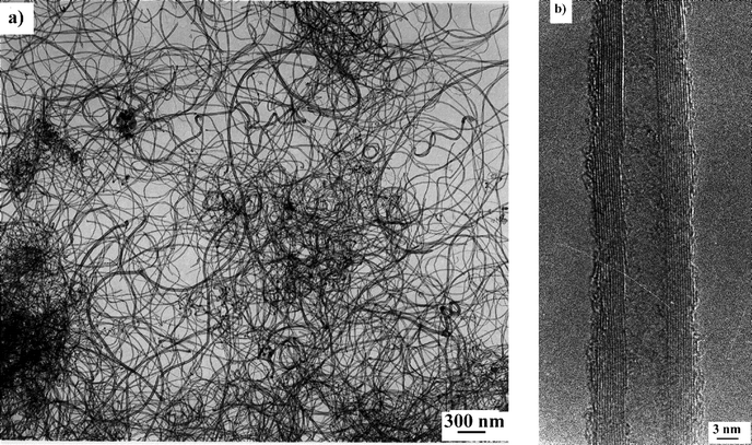 | ||
| Fig. 1 (a) Low and (b) high resolution TEM images of pure multi-wall nanotubes produced on a gram scale over a Co–NaY catalyst (porous impregnation, 5 wt.% of cobalt). | ||
From the TEM observations, the diameter (inner and outer) distribution histograms for the pure nanotubes were established (Fig. 2). The distribution of the inner diameters is sharp and shows diameters in the range 4–8 nm with an average of 6 nm. The outer diameter distribution is broader and is in the range 11–24 nm with an average of 16 nm.
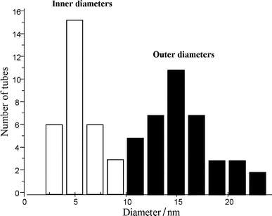 | ||
| Fig. 2 Diameter distribution histograms of pure nanotubes produced on a gram scale over a Co–NaY catalyst made by porous impregnation with 5 wt.% of cobalt. | ||
3.2. Optimization over silica supported catalysts
The second purpose of this work was to optimize the conditions for the production of carbon nanotubes on a gram scale, using Co–silica (pore size 60 Å) catalysts prepared by ion-adsorption precipitation at pH 9. This pH was chosen because according to previous work carried out in our laboratory,15,20 a large amount of well-formed carbon nanotubes covered with a very small amount of amorphous carbon can be produced. Moreover, a definitely larger number of helical tubes were formed over Co–silica catalysts prepared by this method.10,15 These helical nanotubes may lead to very interesting applications owing to their structure and electronic properties.21,22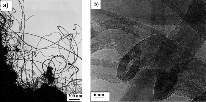 | ||
| Fig. 3 (a) Low and (b) high resolution TEM images of a typical nanotube sample produced over a Co–silica catalyst (ion-adsorption precipitation at pH 9, 12.5 wt.% of metal) at 700°C after 1 h. | ||
The explanation for the different activities of these two catalysts could be that the active metallic particles for the formation of nanotubes are those present on the outer surface of the support. When the catalyst is prepared by porous impregnation, the metal particles are in the inner pores of the support and then they must first migrate from the pores to the outer surface to be active for the formation of the nanotubes. On the other hand, when the catalyst is prepared by ion-adsorption precipitation at pH 9, most of the metal precipitates are on the catalyst surface and hence are directly active for the formation of the tubes, resulting in a better catalyst activity.
The distribution histograms of inner and outer diameters of the nanotubes synthesized under these conditions were also established and are shown in Fig. 4. The inner diameter distribution varies from 3 to 9 nm (average 6 nm) whereas the outer diameter distribution is broader and varies from 9 to 30 nm (average 13 nm).
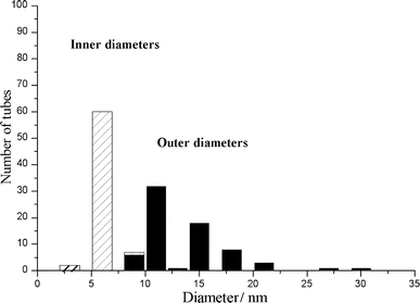 | ||
| Fig. 4 Diameter distribution histograms of nanotubes produced under the optimized conditions over a Co–silica catalyst made by ion-adsorption precipitation at pH 9 with 12.5 wt.% of cobalt. | ||
The carbon deposit increased progressively after 1 h, and it was found to be 13, 23 and 38% at reaction temperatures of 600, 650 and 700°C, respectively.
According to the TEM observations, the best quality nanotubes (neither containing many defects nor any amorphous carbon deposit) was obtained at 700°C. Lower nanotube formation was observed at 650°C, and at 600°C the catalyst was inactive towards nanotube formation, the carbon deposit of 13% being only amorphous carbon.
| Metal concentration (wt.%) | Inner diameters (average)/ nm | Outer diameters (average)/ nm | Carbon deposit (%) | C2H2 conversion (%) |
|---|---|---|---|---|
| 2.5 | 3–12(6) | 10–30(20) | 18 | 12 |
| 5.0 | 3–9(6) | 9–42(17) | 21 | 14 |
| 7.5 | 3–7(6) | 10–22(15) | 30 | 20 |
| 10.0 | 3–7(6) | 8–23(14) | 34 | 22 |
| 12.5 | 3–9(6) | 9–30(13) | 38 | 24 |
TEM pictures of the carbon deposits obtained over the different Co-loaded silica catalysts are given in Fig. 5. It can be seen that the increase in the carbon deposit as a function of the Co content is due to a larger amount of nanotubes being formed and not to a larger amount of amorphous carbon.
 | ||
| Fig. 5 Low resolution TEM images of carbon nanotubes produced by catalytic decomposition of acetylene at 700°C over Co–silica catalysts prepared by ion-adsorption precipitation at pH 9 for various Co contents: (a) 2.5; (b) 5.0; (c) 7.5; and (d) 10.0 wt.%. The image for the sample produced over the catalyst with 12.5 wt.% of Co is shown in Fig. 3(a). | ||
The inner and outer diameters of the nanotubes depend on the metal concentration on the support. In fact, the results in Table 1 can be explained according to a model proposed previously for the growth mechanism of the tubes produced by the catalytic method.23,24 In this model, it was suggested that the inner and outer diameters were governed by the catalyst particle size and the flow rate of hydrocarbon at the catalyst particle surface, respectively. As can be seen from Table 1, the inner diameter of the tubes formed has a constant value of 6 nm whatever the catalyst metal content. Moreover, this value corresponds exactly to the pore size of the silica support (6 nm). These observations suggest that pore size of the support and hence the size of the metallic particles which migrate from the inner pores to the outer surface of the support should have an optimum size of 6 nm for tube growth. That optimum size of ca. 6 nm diameter may depend on a stable carbon ring or cup that must be formed around the catalyst active particle prior to the nanotube growth.
Another interesting observation from the results in Table 1 is that the average outer diameter of the carbon nanotubes decreases when the activity of the catalyst increases. When the activity is low (low carbon deposit due to the presence of less active sites), the acetylene flow rate per active site is high and hence the number of turbostratic layers of the nanotubes is high, resulting in thicker nanotubes.
3.3. Effect of the catalyst support on nanotube formation
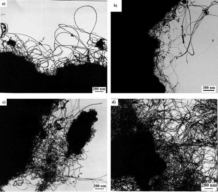
The influence of the support on the mechanism of filament formation was described previously.25–28 The growth process was shown to be strongly dependent on the catalyst–support interaction.Applying the ion-adsorption precipitation method (at pH 9), different supports such as 60 Å silica, quartz, fumed alumina and different zeolites (ZSM-5, NaY and 13X) were prepared and tested in the catalytic decomposition of acetylene. The synthesis of carbon nanotubes was carried out at 700°C with acetylene as carbon source, a contact time of 1 h and flow rates of 30 ml min−1 of acetylene and 300 ml min−1 of nitrogen.
Results obtained over the different supports are summarized in Table 2. TEM pictures relating to the different samples of nanotubes produced in this study are shown in Fig. 6.
| Support | Pore size of the support/Å | Carbon deposit (%) | Average inner diametera/nm | Average outer diametera/nm |
|---|---|---|---|---|
| a T for thin tubes and L for large tubes. | ||||
| Silica 60 Å | 60 | 38 | 6 (L) | 13 (L) |
| Silica fumed | No pores | 35 | Amorphous carbon | |
| Quartz | No pores | No activity | — | — |
| Alumina fumed | No pores | 90 | 4 (T); 6 (L) | 8 (T); 12 (L) |
| 13 X | 7.4 | 40 | 4 (T); 6 (L) | 9 (T); 14 (L) |
| ZSM-5 | 5.5 | 20 | 7 (L) | 14 (L) |
| NaY | 7.4 | 25 | 6 (L) | 16 (L) |
 | ||
| Fig. 6 Low magnification TEM images of nanotubes produced by catalytic decomposition of acetylene at 700°C over various supported cobalt catalysts prepared by ion-adsorption precipitation at pH 9 and with 12.5 wt.% of metal. (a) Fumed alumina supported catalyst; (b) zeolite 13X; (c) zeolite ZSM-5; and (d) zeolite NaY. | ||
Significant differences were observed among the three Co–silica catalysts. Depending on the type of support, carbon deposits with different morphologies were produced. In the case of fumed silica and quartz, no nanotube formation was observed. With fumed alumina as catalyst support, the carbon deposit increased to 90%, corresponding to a carbon conversion of 50%, but no helical tubes were detected in this sample. Moreover, two different kinds of nanotubes were observed when alumina was used as catalyst support [Fig. 6(a)]: thin tubes (T), being the major fraction, with inner and outer diameters of approximately 4 and 8 nm, respectively (Table 2); and large tubes (L), being the minor fraction, with inner and outer diameters of 6 and 12 nm, respectively (Table 2).
The carbon deposit produced over the zeolite 13X supported catalyst was also constituted of two kinds of nanotubes [Fig. 6(b)]. The different nanotubes (T and L) present in this sample were similar to those produced on a fumed alumina support. The main difference was the higher proportion of large tubes (L) obtained on the zeolite 13X catalyst compared with that obtained over the alumina catalyst. The other difference was the larger average outer diameter of the tubes obtained on the zeolite 13X catalyst. This increase in the outer diameter of the tubes can again be related to the catalyst activity. In fact, at a given acetylene flow rate, the decrease in catalyst activity (due to less active sites) from alumina to zeolite 13X leads to the presence of a larger amount of carbon per active site, resulting in the formation of thicker nanotubes.
Using ZSM-5 and NaY zeolites as catalyst supports, and applying ion-adsorption precipitation as the catalyst preparation method, only large tubes (L) were produced during the catalytic hydrocarbon decomposition [Fig. 6(c) and (d), respectively]. However, even if the carbon deposits were of the same order of magnitude for the two catalysts, very few carbon nanotubes were formed over zeolite NaY catalyst, whereas the nanotube formation was better over zeolite ZSM-5. [Note that when Co–NaY catalyst was prepared by impregnation, it had a very high nanotube growth activity (see Section 3.1).]
3.4. Effect of pH on catalyst preparation
Silica 60 and zeolite 13X supported catalysts were prepared at three different pH values (9, 11 and 13) and were tested in nanotube formation. The results are reported in Table 3.| Support | pH | Carbon deposit (%) | Co loading (wt.%)a ** | Average inner diameterb/nm * | Average outer diameterb/nm * | Remarks |
|---|---|---|---|---|---|---|
| a From Proton Induced X-ray Emission (PIXE).b T for thin tubes and L for large tubes. | ||||||
| Silica 60 Å | 9 | 38 | 12.5 | 6 (L) | 13 (L) | Helices |
| 11 | 46 | 11.2 | 6 (L) | 21 (L) | No helices | |
| 13 | 51 | 10.9 | 6 (L) | 23 (L) | No helices | |
| Zeolite 13X | 9 | 43 | 10.6 | 4 (T); 6 (L) | 9 (T); 14 (L) | No helices |
| 11 | 48 | 10.2 | 4 (T); 6 (L) | 10 (T); 17 (L) | No helices | |
| 13 | 39 | 9.0 | 4 (T); 6 (L) | 12 (T); 8 (L) | No helices | |
It can be seen that the carbon deposit is virtually constant whatever the pH. However, according to TEM observations, the nanotube formation activity increased when the pH decreased, leading to a diminution of the nanotube outer diameter. The decrease in nanotube formation activity at higher pH values may be due to the lower cobalt content on the catalyst surface and/or to the formation of different chemical species of Co at the three different pH values. Moreover, the presence of helical tubes was observed only on the most active Co–silica catalyst prepared by ion-adsorption precipitation at pH 9.
4. Conclusions
We have shown that the catalytic synthesis of multi-wall carbon nanotubes over supported Co catalysts can be very efficient. By varying the catalyst and reaction conditions, it was possible to optimize the process towards the gram scale production of carbon deposits. When the catalyst support is zeolite, the purification of the nanotubes is easy and we are now able to synthesize tens of grams of pure carbon nanotubes using the catalytic process.The preparation method for the Co–silica catalysts and the reaction conditions were optimized to increase the selectivity to produce helical carbon nanotubes by catalytic decomposition of acetylene. Applying silica supported catalysts, the gram scale production of carbon deposits was also achieved, but elimination of the amorphous carbon, the silica support and the metals still remained a problem and hence pure nanotube samples could not be produced using this support.
The growth mechanism of nanotubes produced in this way was also investigated and this revealed that the diameter of the catalyst particles should be close to that of the inner tube, while the number of turbostratic layers of each nanotube might depend on the flow rate of acetylene per active site. The outer layers of the multi-wall nanotubes seem to be formed simultaneously with the inner layer.
The type of catalyst support also played an important role in the effectiveness of the catalyst particles, leading to different activities for nanotube production. Different amounts of nanotubes with different morphologies and diameters could be produced over the catalyst support depending on its nature.
Acknowledgements
The authors thanks the European Commission (TMR Program, NAMITECH network, contract No. ERB FMRX96-0067, DG 12-MIHT), the Belgian Program on Inter University Poles of Attraction initiated by the Belgian State, Prime Minister's Office for Scientific Technical and Cultural Affairs (OSTC–PAI–IUAP No. 4/10 on Reduced Dimensionality Systems), and Z. K. acknowledges a Hungarian State Eotvos Fellowship.References
- S. Iijima, Nature (London), 1991, 354, 56 CrossRef CAS.
- M. M. J. Treacy, T. W. Ebbesen and J. M. Gibson, Nature (London), 1998, 381, 678 CrossRef.
- M. R. Pederson and J. Q. Broughton, Phys. Rev. Lett., 1992, 69, 2682 CrossRef CAS.
- J. W. Mintmire, B. I. Dunlap and C. T. White, Phys. Rev. Lett., 1992, 68, 631 CrossRef CAS.
- P. M. Ajayan and S. Iijima, Nature (London), 1993, 361, 333 CrossRef CAS.
- D. H. Robertson, D. W. Brenner and J. W. Mintmire, Phys. Rev. B, 1992, 45, 12592 CrossRef.
- M. José-Yacaman, M. Miki-Yoshida, L. Rendon and J. G. Santiesteban, Appl. Phys. Lett., 1993, 62, 202 CrossRef CAS.
- M. José-Yacaman, H. Terrones, L. Rendon and J. M. Rodriguez, Carbon, 1995, 33, 669 CrossRef CAS.
- N. M. Rodriguez, J. Mater. Res., 1993, 8, 3233 Search PubMed.
- V. Ivanov, J. B.Nagy, Ph. Lambin, A. Lucas, X. B. Zhang, X. F. Zhang, D. Bernaerts, G. Van Tendeloo, S. Amelincks and J. Van Landuyt, Chem. Phys. Lett., 1994, 223, 329 CrossRef CAS.
- W. Z. Li, S. S. Xie, L. X. Qian, B. H. Chang, B. S. Zou, W. Y. Zhou, R. A. Zhao and G. Wang, Science, 1996, 274, 1701 CrossRef CAS.
- M. Terrones, N. Grobert, J. Olivares, J. P. Zhang, H. Terrones, K. Kordatos, W. K. Hsu, J. P. Hare, P. Townsend, K. Prassides, A. K. Cheetham, H. W. Kroto and D. R. M. Walton, Nature (London), 1997, 388, 52 CrossRef CAS.
- C. N. R. Rao, R. Sen, B. C. Satishkumar and A. Govindaraj, Chem. Commun., 1998, 1525 RSC.
- S. Fan, M. G. Chapline, N. R. Franklin, T. W. Tombler, A. M. Cassel and H. Dai, Science, 1999, 283, 512 CrossRef CAS.
- A. Fonseca, K. Hernadi, J. B.Nagy, D. Bernaerts and A. A. Lucas, J. Mol. Catal., 1996, 107, 159 Search PubMed.
- K. Hernadi, A. Fonseca, J. B.Nagy, D. Bernaerts, A. Fudala and A. A. Lucas, Zeolites, 1996, 17, 416 CrossRef CAS.
- K. Hernadi, A. Fonseca, J. B.Nagy, D. Bernaerts, J. Riga and A. Lucas, Synth. Met., 1996, 77, 31 CrossRef CAS.
- V. Ivanov, A. Fonseca, J. B.Nagy, A. Lucas, P. Lambin, D. Bernaerts and X. B. Zhang, Carbon, 1995, 33, 1727 CrossRef CAS.
- J.-F. Colomer, P. Piedigrosso, I. Willems, C. Journet, P. Bernier, G. Van Tendeloo, A. Fonseca and J. B.Nagy, J. Chem. Soc., Faraday Trans., 1998, 94, 3753 RSC.
- K. Hernadi, A. Fonseca, P. Piedigrosso, M. Delvaux, J. B.Nagy, D. Bernaerts and J. Riga, Catal. Lett., 1997, 48, 229 Search PubMed.
- Ph. Lambin, A. Fonseca, J. P. Vigneron, J. B.Nagy and A. A. Lucas, Chem. Phys. Lett., 1995, 245, 85 CrossRef CAS.
- K. Agaki, R. Tamura, M. Tsukada, S. Itoh and S. Ihara, Phys. Rev. Lett., 1995, 74, 2307 CrossRef.
- A. Fonseca, K. Hernadi, J. B.Nagy, Ph. Lambin and A. A. Lucas, Synth. Met., 1996, 77, 235 CrossRef CAS.
- A. Fonseca, K. Hernadi, J. B.Nagy, Ph. Lambin and A. A. Lucas, Carbon, 1995, 33, 1759 CrossRef CAS.
- A. Sacco, Jr, F. W. Geurts, G. A. Jablonski, S. Lee and R. A. Gately, J. Catal., 1989, 119, 322 CrossRef CAS.
- G. A. Jablonski, F. W. Geurts and A. Sacco, Carbon, 1992, 30, 87 CrossRef CAS.
- P. E. Nolan and D. C. Lynch, Carbon, 1994, 32, 477 CrossRef CAS.
- R. T. K. Baker, Carbon, 1989, 7, 315 CrossRef CAS.
| This journal is © the Owner Societies 2000 |