Towards tailored topography: facile preparation of surface-wrinkled gradient poly(dimethyl siloxane) with continuously changing wavelength†
Kai Uwe
Claussen‡
a,
Moritz
Tebbe‡
b,
Reiner
Giesa
a,
Alexandra
Schweikart
b,
Andreas
Fery
b and
Hans-Werner
Schmidt
*a
aDepartment of Macromolecular Chemistry I, University of Bayreuth, 95440, Bayreuth, Germany. E-mail: hans-werner.schmidt@uni-bayreuth.de; Fax: +49 921 55-3206; Tel: +49 921 55-3200
bDepartment of Physical Chemistry II, University of Bayreuth, 95440, Bayreuth, Germany. E-mail: andreas.fery@uni-bayreuth.de; Fax: +49 921 55-2059; Tel: +49 921 55-2753
First published on 21st September 2012
Abstract
Poly(dimethyl siloxane) with a compositional gradient was fabricated via a precision syringe pump setup. Stretching of the substrate and subsequent oxygen plasma oxidation resulted in a continuously changing wrinkle wavelength on the surface upon relaxation. This approach is a powerful tool for designing gradient surfaces with tailored topography.
Surface instabilities in thin films can be utilized for the spontaneous formation of patterned surfaces.1 Current scientific interest focuses on wrinkle formation in layers that are coupled to elastic poly(dimethyl siloxane) (PDMS) substrates.2,3 The wrinkle process comprises stretching of a soft PDMS substrate4,5 and subsequent oxygen plasma treatment, resulting in a hard SiO2-like (SiOx-) layer on the surface.6,7 Upon relaxation, sinusoidal wrinkles with a uniform wrinkle wavelength are formed due to the buckling instability that relieves stresses.8 The wrinkle wavelength λ of the buckled bilayer system can be calculated for high strains according to eqn (1).9
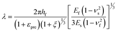 | (1) |
Hence, the wrinkling wavelength (and so the surface pattern) can be controlled10 by altering the thickness hf of the layer or the Young's modulus Es of the substrate if Ef remains constant.8 Since the wrinkle wavelength directly determines the surface pattern, wrinkling of PDMS provides a powerful tool to design surfaces with tailored topography.2,11 These synthetic micro- and nanostructured surfaces can be exploited for a variety of applications,12 for instance, tuning of surface adhesion,13 preparation of tunable diffraction gratings,14,15 microlenses,16 nanochannels for microfluidics,17 ceramic nanopatterns,18 particle alignment,19 lithography,20 measuring the mechanical properties of thin films21 and for engineering cell–material interfaces.22,23 Particularly in the latter case, gradient surfaces are in high demand in order to study the balance of substrate chemistry and topography.25,26 As a consequence of the variety of applications, the preparation of PDMS materials with changing wrinkling wavelength is the subject of recent research efforts.27,28 Although theoretical studies concerning the elastic buckling of PDMS gradient materials have been carried out,29 PDMS gradient materials with a continuously changing wrinkle wavelength were hitherto unavailable. Recently, we showed that the Young's modulus of PDMS substrates can be continuously changed.30,31 The setup allows the preparation of different PDMS gradient geometries with high reproducibility. According to eqn (1), the application of the wrinkling process to a PDMS gradient material leads to a surface with continuously changing topography. Herein, we report the first gradient surface-wrinkled PDMS material. Moreover, the longitudinal gradient is prepared on a centimeter scale that allows macroscopic surface patterning with sub-micron structures.
The PDMS system of choice for the presented process is Sylgard 184 (DOW Corning) which is usually applied in a 10![[thin space (1/6-em)]](https://www.rsc.org/images/entities/char_2009.gif) :1 ratio (w/w) of siloxane and curing agent and requires a thermal curing step. By variation of the ratio of 10:1 (PDMS-hard) to 25:1 (PDMS-soft) a Young's modulus variation from 1.8 MPa to 0.2 MPa can be achieved, respectively. According to eqn (1), the variation in modulus by a factor of 9 led us to expect a maximum wrinkle wavelength variation of factor 2.1. PDMS materials were prepared via a previously described procedure.30 In brief, the siloxane and curing agent had to be mixed before using the syringe pumps due to the large differences in viscosity (see ESI†). Then, syringes were filled with the uncured PDMS-hard and PDMS-soft mixtures and mounted on a syringe pump setup. The mixtures were pumped at different volume ratios but at a constant total flow rate. After uniting and mixing, the mixture was processed into a mold and cured. First, discrete mixtures of different ratios of PDMS-hard and PDMS-soft were prepared.27 Cylindrical specimens of each discrete composition were punched and the compressive modulus was determined.32 Tensile tests were also carried out and the Young's modulus in tension was analyzed. By increasing the amount of the PDMS-hard content in the PDMS-hard/PDMS-soft samples with discrete composition, the curing agent content is also increased. This, in return, increased the crosslink density and led to an increase in tensile and compressive modulus of the discrete composition. We found an excellent agreement of the determined values with fits based on the logarithmic mixing rule (Fig. 1).24
:1 ratio (w/w) of siloxane and curing agent and requires a thermal curing step. By variation of the ratio of 10:1 (PDMS-hard) to 25:1 (PDMS-soft) a Young's modulus variation from 1.8 MPa to 0.2 MPa can be achieved, respectively. According to eqn (1), the variation in modulus by a factor of 9 led us to expect a maximum wrinkle wavelength variation of factor 2.1. PDMS materials were prepared via a previously described procedure.30 In brief, the siloxane and curing agent had to be mixed before using the syringe pumps due to the large differences in viscosity (see ESI†). Then, syringes were filled with the uncured PDMS-hard and PDMS-soft mixtures and mounted on a syringe pump setup. The mixtures were pumped at different volume ratios but at a constant total flow rate. After uniting and mixing, the mixture was processed into a mold and cured. First, discrete mixtures of different ratios of PDMS-hard and PDMS-soft were prepared.27 Cylindrical specimens of each discrete composition were punched and the compressive modulus was determined.32 Tensile tests were also carried out and the Young's modulus in tension was analyzed. By increasing the amount of the PDMS-hard content in the PDMS-hard/PDMS-soft samples with discrete composition, the curing agent content is also increased. This, in return, increased the crosslink density and led to an increase in tensile and compressive modulus of the discrete composition. We found an excellent agreement of the determined values with fits based on the logarithmic mixing rule (Fig. 1).24
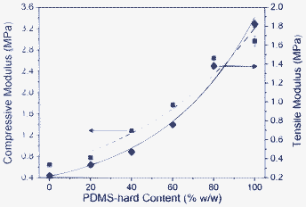 | ||
| Fig. 1 Compressive modulus (blue squares) and E-modulus (black diamonds) as functions of the mixing ratio of PDMS-hard and PDMS-soft. The blue and the black curves represent fits according to the logarithmic mixing rule.24 With these fits each measured Young's modulus can be correlated to a PDMS-hard content. | ||
Then, by application of an optimized on–off flow profile of PDMS-hard and PDMS-soft (at a total flow rate of 25 μL s−1) a longitudinal PDMS gradient material30 was obtained after thermal curing (Fig. 2). The on–off flow profile allows the preparation of the steepest gradients because the gradient generation depends only on the mixing performance of the static mixer (Fig. 2a). After curing, cylindrical specimens were punched every centimeter and the compressive modulus at each sample position was determined. Using the exponential fit shown in Fig. 1, the compressive modulus of each cylinder could be correlated to a discrete composition (and E-modulus). In this way, the longitudinal PDMS gradient can be visualized, showing the continuous decrease of PDMS-hard (and so increase of PDMS-soft) content along the length of the sample (Fig. 2b).
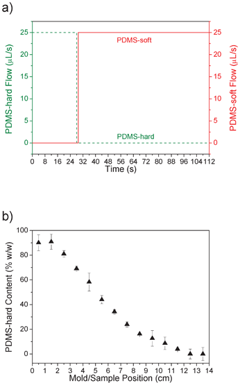 | ||
| Fig. 2 a) Flow profile of PDMS-hard (dashed green line) and PDMS-soft (solid red line) in dependency on the time. The dead volume of the static mixer causes a 56 s delay before the mold starts filling. b) Calculated PDMS content (black triangles) along the length of the mold/sample. Every centimeter a cylindrical specimen was punched and the compressive modulus was determined. Using the fit in Fig. 1 (blue curve), the composition was calculated. | ||
Common procedures for wrinkling PDMS substrates involve the uniaxial straining of the sample and subsequent oxygen plasma treatment.2 In the case of PDMS gradients, the applied load does not distribute uniformly across the sample causing much higher strains in the softer regions (see ESI†). This prevents the transfer of the continuously changing modulus into a stepless varying wrinkle wavelength. Therefore, the PDMS gradient was embedded into a matrix of PDMS-hard. After applying a load to the matrix the embedded gradient is subjected to a constant force field and exhibits an uniform strain independent of the position (Fig. 3). In this way, a PDMS gradient sample was embedded in the matrix, which was then cured, and the entire sample uniaxially stretched and treated with oxygen plasma as described above. After relaxation, this method resulted in a continuous change of the wrinkle wavelength, dependent on the Young's modulus of the substrate according to eqn (1). The interface between the gradient sample and the surrounding matrix is shown in Fig. S1 (see ESI†) and is reminiscent of the postulated y-branching29 that occurs for a steep gradient parallel to the wrinkle direction and consequently a steplike transition between different wavelengths.
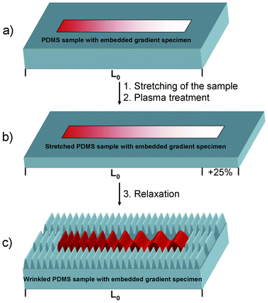 | ||
| Fig. 3 Wrinkling of PDMS gradient specimens. a) A PDMS gradient specimen is embedded into a PDMS-hard mixture and cured. b) The entire sample with initial length L0 is strained to 125% and plasma treated. c) After relaxation, the gradient specimen shows a variation of wrinkle wavelength at the surface in contrast to the surrounding PDMS-hard regions (note that the SiOx-layer thickness in the sketch is exaggerated for better visualization of the principle). | ||
Over the entire gradient sample, the wrinkle wavelength changed continuously from 700 nm to 1200 nm (Fig. 4). This factor of 1.7 matches well with our estimate of 2.1 given by the maximum E-modulus variation of cured PDMS-hard and PDMS-soft. Due to the uniform wrinkle wavelength at each measuring spot these SEM images are representative of the topography at the specific sample positions.
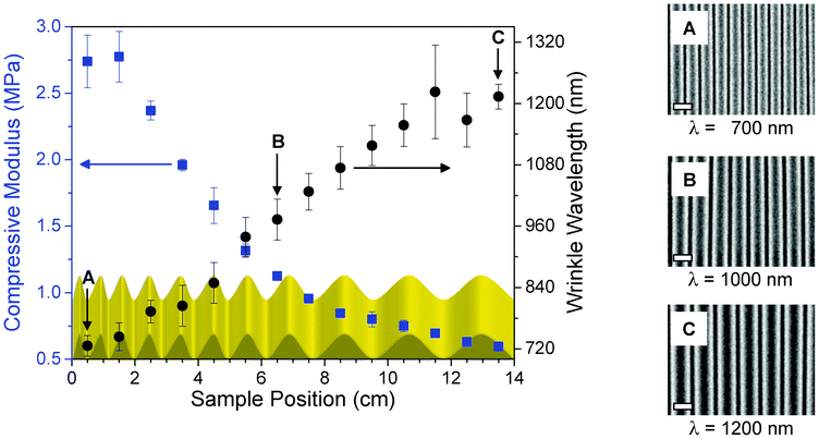 | ||
| Fig. 4 Correlation of compressive modulus (blue squares) and wrinkle wavelength (black dots) of the surface-wrinkled PDMS gradient material. For illustration, the continuously changing wrinkle wavelength is schematically shown as a function of the sample position. The SEM images show the different wrinkle wavelength at the sample positions 0.5 (A), 6.5 (B) and 13.5 cm (C). The white scale bar in the lower left corner represents 1000 nm. | ||
SEM images revealed a uniform wrinkle wavelength at each measuring spot (Fig. S2, see ESI†). Over an area of 80 μm × 120 μm the wrinkle wavelength λ remains almost constant, considering the error given in Fig. 4. This uniformity is a strength of the presented approach and allows the preparation of highly reproducible surfaces. Note that the cracks perpendicular to the wrinkles (Fig. S2, see ESI†) are a well known phenomenon and a consequence of the relaxation process.2
According to eqn (1) the increase of wrinkle wavelength λ correlates with the decrease of the compressive (and thus the tensile) modulus.33 The wrinkle wavelength also depends linearly on the layer thickness hf. To exclude the possibility of varying layer thickness being responsible for the change in wrinkle wavelength, the dependency of the film thickness on the sample position was investigated (Fig. S3, see ESI†). The thickness of the layer was calculated to be around 6 nm and showed no significant dependency on the varying composition of the gradient substrate. Therefore, the continuously changing wrinkle wavelength can be attributed exclusively to the change of the Young's modulus along the length of the sample.
In summary, we present a facile preparation method for macroscopic surface-wrinkled PDMS gradient materials. The continuously changing E-modulus of the PDMS gradient substrate was transferred into a stepless varying wrinkle wavelength of the SiOx-like surface. Since the wrinkle wavelength determines the topography of the sample, this approach allows the tailoring of surfaces with a continuously varying surface pattern. This new lithography-free tool could be very interesting for the design of tailored gradient surfaces and their potential application for diffraction gratings14,15, microlenses,16 microfluidics17 and cell adhesion studies.22,23
Acknowledgements
Funding of this work by the Deutsche Forschungsgemeinschaft (DFG) within the program “Bionik”, grant number SCHM 703/6-1 and SCHE 603/7-1, and the Elitenetzwerk Bayern (ENB), Macromolecular Science, is gratefully acknowledged. We thank B. Glatz for help with mechanical testing and O. Stiehl for error analysis.Notes and references
- J. Y. Chung, A. J. Nolte and C. M. Stafford, Adv. Mater., 2011, 23, 349 CrossRef CAS.
- A. Schweikart and A. Fery, Microchim. Acta, 2009, 165, 249 CrossRef CAS.
- N. Bowden, W. T. S. Huck, K. E. Paul and G. M. Whitesides, Appl. Phys. Lett., 1999, 75, 2557 CrossRef CAS.
- J. Genzer and K. Efimenko, Science, 2000, 290, 2130 CrossRef CAS.
- K. Efimenko and J. Genzer, Adv. Mater., 2001, 13, 1560 CrossRef CAS.
- K. Efimenko, W. E. Wallace and J. Genzer, J. Colloid Interface Sci., 2002, 254, 306 CrossRef CAS.
- M. Ouyang, C. Yuan, R. J. Muisener, A. Boulares and J. T. Koberstein, Chem. Mater., 2000, 12, 1591 CrossRef CAS.
- A. L. Volynskii, S. Bazhenov, O. V. Lebedeva and N. F. Bakeev, J. Mater. Sci., 2000, 35, 547 CrossRef CAS.
- H. Jiang, D.-Y. Khang, J. Song, Y. Sun, Y. Huang and J. A. Rogers, Proc. Natl. Acad. Sci. U. S. A., 2007, 104, 15607 CrossRef CAS.
- J.-Y. Park, H. Y. Chae, C.-H. Chung, S. J. Sim, J. Park, H. H. Lee and P. J. Yoo, Soft Matter, 2010, 6, 677 RSC.
- C. Provin and T. Fujii, Lab Chip, 2011, 11, 2948 RSC.
- S. Yang, K. Khare and P.-C. Lin, Adv. Funct. Mater., 2010, 20, 2550 CrossRef CAS.
- E. P. Chan, E. J. Smith, R. C. Hayward and A. J. Crosby, Adv. Mater., 2008, 20, 711 CrossRef CAS.
- C. Harrison, C. M. Stafford, W. Zhang and A. Karim, Appl. Phys. Lett., 2004, 85, 4016 CrossRef CAS.
- C. Yu, K. O'Brien, Y.-H. Zhang, H. Yu and H. Jiang, Appl. Phys. Lett., 2010, 96, 041111 CrossRef.
- E. P. Chan and A. J. Crosby, Adv. Mater., 2006, 18, 3238 CrossRef CAS.
- S. Chung, J. H. Lee, M.-W. Moon, J. Han and R. D. Kamm, Adv. Mater., 2008, 20, 3011 CrossRef CAS.
- S. Park and A. Böker, J. Mater. Chem., 2011, 21, 11734 RSC.
- A. Schweikart, N. Pazos-Perez, R. A. Alvarez-Puebla and A. Fery, Soft Matter, 2011, 7, 4093 RSC.
- B. D. Gates, Q. Xu, M. Stewart, D. Ryan, C. G. Willson and G. M. Whitesides, Chem. Rev., 2005, 105, 1171 CrossRef CAS.
- A. Agrawal, P. Luchette, P. Palffy-Muhoray, S. L. Biswal, W. G. Chapman and R. Verduzco, Soft Matter, 2012, 8, 7138 RSC.
- X. Jiang, S. Takayama, X. Qian, E. Ostuni, H. Wu, N. Bowden, P. LeDuc, D. E. Ingber and G. M. Whitesides, Langmuir, 2002, 18, 3273 CrossRef CAS.
- G. Bartalena, Y. Loosli, T. Zambelli and J. G. Snedeker, Soft Matter, 2012, 8, 673 RSC.
- R. W. Gray and N. G. McCrum, J. Polym. Sci., Part A: Polym. Chem., 1969, 7, 1329 CAS.
- T. G. Ruardy, J. M. Schakenraad, H. C. van der Mei and H. J. Busscher, Surf. Sci. Rep., 1997, 29, 3 CrossRef.
- M. S. Kim, G. Khang and H. B. Lee, Prog. Polym. Sci., 2008, 33, 138 CrossRef CAS.
- E. A. Wilder, S. Guo, S. Lin-Gibson, M. J. Fasolka and C. M. Stafford, Macromolecules, 2006, 39, 4138 CrossRef CAS.
- G. Miquelard-Garnier, A. B. Croll, C. S. Davis and A. J. Crosby, Soft Matter, 2010, 6, 5789 RSC.
- J. Yin and X. Chen, Philos. Mag. Lett., 2010, 90, 423 CrossRef CAS.
- K. U. Claussen, R. Giesa, T. Scheibel and H.-W. Schmidt, Macromol. Rapid Commun., 2012, 33, 206 CrossRef CAS.
- K. U. Claussen, T. Scheibel, H.-W. Schmidt and R. Giesa, Macromol. Mater. Eng., 2012 DOI:10.1002/mame.201200032.
- O. H. Yeoh, Polym. Test., 1987, 7, 121 CrossRef CAS.
- A. Gent, Engineering with Rubber, Hanser Publications, Munich, 2001, p. 365 Search PubMed.
Footnotes |
| † Electronic supplementary information (ESI) available: Experimental section and additional figures. See DOI: 10.1039/c2ra21859c |
| ‡ These authors contributed equally to this work. |
| This journal is © The Royal Society of Chemistry 2012 |