 Open Access Article
Miniaturized lithium-ion batteries for on-chip energy storage
Zhangci
Wang†
,
Yuhang
Chen†
,
Yuyu
Zhou†
,
Jun
Ouyang
,
Shuo
Xu
and
Lu
Wei
 *
*
School of Materials Science and Engineering, Huazhong University of Science and Technology, Wuhan 430074, China. E-mail: lwei@hust.edu.cn
First published on 12th September 2022
Abstract
The development of microelectronic products increases the demand for on-chip miniaturized electrochemical energy storage devices as integrated power sources. Such electrochemical energy storage devices need to be micro-scaled, integrable and designable in certain aspects, such as size, shape, mechanical properties and environmental adaptability. Lithium-ion batteries with relatively high energy and power densities, are considered to be favorable on-chip energy sources for microelectronic devices. This review describes the state-of-the-art of miniaturized lithium-ion batteries for on-chip electrochemical energy storage, with a focus on cell micro/nano-structures, fabrication techniques and corresponding material selections. The relationship between battery architecture and form-factors of the cell concerning their mechanical and electrochemical properties is discussed. A series of on-chip functional microsystems created by integrating micro-lithium-ion batteries are highlighted. Finally, the challenges and future perspectives of miniaturized lithium-ion batteries are elaborated with respect to their potential application fields.
1. Introduction
The emergence of advanced microelectronic products, such as micro-electromechanical systems, micro-sensors, micro-robots and implantable medical devices, accelerates the development of on-chip miniaturized electrochemical energy storage devices.1–3 Traditional electrochemical energy storage devices (such as commercial lithium-ion batteries and supercapacitors) with a sandwich-type cell structure are difficult to apply in some microsystems owing to the limitations of cell sizes, form factors and integrability.4–6 Customized micro-electrochemical energy storage devices with the features of light weight, shape-versatility and ultra-compactness, can be integrated with microsystems to satisfy specific demands for on-chip applications.7,8 Among them, micro-lithium-ion batteries (micro-LIBs) with relatively high energy/power densities and good cycle life, are considered to be preferable candidates for miniaturized power supply.9–11The development milestones and critical evolution of micro-LIBs are presented in Fig. 1. Back in 1969, Liang and Bro pioneered a solid-state thin-film structured lithium battery (a high-voltage laminated Li/LiI/AgI cell) and opened the prelude of thin film batteries.12 Later, Kanehori et al. reported a thin film solid-state lithium secondary cell (Li/Li3.6Si0.6P0.4O4/TiS2).13 In 2000, Branci et al. developed novel vitreous tin oxide-based thin film electrodes for micro-LIBs.14 However, the miniaturized LIBs mentioned above are still based on a sandwich-type structure. In 2007, an all-solid-state micro-LIB based on an in-plane interdigital structure was proposed.15 Such a structure was considered to be easier for on-chip integration. After decades of development, micro-LIBs experienced evolution from a laminated thin film structure to a planar interdigital structure and then to 3D architectures. In the past ten years, micro-LIBs with a nanostructured 3D LiCoO2 cathode16 or 3D LiMn2O4 (ref. 17) anode have been explored. Moreover, various advanced micro/nano-fabrication technologies such as 3D printing,18 nanoimprint lithography19 and atomic layer deposition20 were utilized to realize complex 3D microstructures for micro-LIBs. Recently, several advanced microsystems integrated with printed micro-LIBs have been realized for Internet of Things (IoT) applications.21
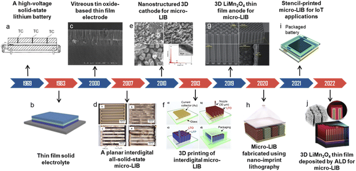 | ||
| Fig. 1 The development milestones and critical evolution of miniaturized lithium-ion batteries. (c) Reproduced with permission from ref. 14, Copyright© 2000, Elsevier B.V. (d) Reproduced with permission from ref. 15, Copyright© 2007, Elsevier B.V. (e) Reproduced with permission from ref. 16, Copyright© 2010, John Wiley & Sons, Inc. (f) Reproduced with permission from ref. 18, Copyright© 2013, John Wiley & Sons, Inc. (g) Reproduced with permission from ref. 17, Copyright© 2019, Royal Society of Chemistry. (h) Reproduced with permission from ref. 19, Copyright© 2020, John Wiley & Sons, Inc. (i) Reproduced with permission from ref. 21, Copyright© 2021, Elsevier B.V. (j) Reproduced with permission from ref. 20, Copyright© 2022, John Wiley & Sons, Inc. | ||
Designing a reasonable microelectrode configuration is one of the significant factors for obtaining the preferable performances of micro-LIBs. Since micro-LIBs typically cover a total area of 1 mm2 to 1 cm2, microelectrodes tend to be less than 10 μm in thickness; or the size of the whole 3D device is 1 to 10 mm3 containing the whole device and related packaging.22–24 The compact size of micro-LIBs with the capability to satisfy customized requirements and compatible performance makes micro-LIBs a preferable energy source for miniaturized electronics.25–27 Additionally, it is possible to integrate micro-LIBs on flexible substrates for wearable electronics.28,29
In recent years, nanotechnology has been having a large effect on energy science and technologies. Applying nanomaterials to next-generation energy storage devices is a great impetus.30–32 In comparison with traditional batteries based on micro-materials for electrodes, nanomaterial-made micro-LIBs may have improved ion diffusion/transport capacity. Moreover, with highly controllable microstructures and form factors of cells, they can occupy all the available space in target electronic products and thus provide high energy and power densities.33,34
In this review, recent advances in miniaturized or micro-LIBs for on-chip energy storage are presented, with a focus on cell micro/nanostructures, manufacturing techniques and corresponding material selections. The relationship between battery configuration and form-factors of the cell concerning their mechanical and electrochemical properties is discussed. A series of on-chip functional microsystems created by integrating micro-LIBs are highlighted. The challenges and future perspectives of on-chip micro-LIBs are elaborated with respect to their potential application fields.
2. Microstructure design
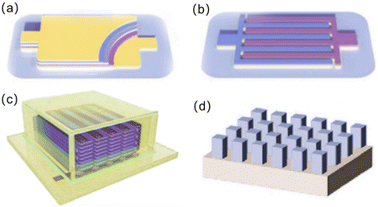
Different application scenarios for micro-LIBs require the design of corresponding cell structures to meet the actual demands. For instance, an important application of micro-LIBs is as wearable power for smart and personalized electronics. Then, the matched micro-LIBs require excellent deformation and stress resistance. Based on this, choosing a suitable cell structure should be taken into serious consideration. Currently, micro-LIBs can be classified into four categories on the basis of different cell microstructure designs (Fig. 2): (a) a laminated thin film structure, (b) a planar interdigital structure, (c) a 3D interdigital structure and (d) other types of 3D architectures.34–37Similar to the traditional sandwich-type lithium-ion batteries, micro-LIBs based on a laminated thin film structure (Fig. 2a) consist of multi-thin-layers arranged in the order of substrate, bottom current collector, anode, electrolyte, separator, cathode and top current collector. Such a structure has good rate performance, high cycling stability and good mechanical flexibility. Moreover, owing to its ability to completely utilize the entire space, the volume utilization is high.39,40
The planar interdigital structure (Fig. 2b) consists of the cathode and anode interdigitally arranged on a substrate, and the distance between adjacent electrode fingers ranges from several microns to tens of microns. Micro-LIBs based on a planar interdigital structure have unique advantages, including high specific surface area of electrodes and short paths for ion diffusion/transport by further reducing the distance between the interdigital electrodes, thus achieving high power density.41–43 Moreover, electrodes of micro-LIBs with such an in-plane structure do not need an additional separator, and can be designed with various patterns for on-chip integration.
Microelectrodes with 3D interdigital structures usually consist of multilayer filaments (Fig. 2c) or vertically aligned, isolated vertical columns grown on interdigital current collectors.44–48 Such structures effectively use the upper space above the substrate for more active material loading, thus significantly improving the areal energy density. In addition to a 3D interdigital structure, other types of 3D microstructures were also explored, including 3D microtubes, 3D interlaced pillars and 3D coaxial structures (Fig. 2d and 3). For a 3D microtube structure, the current response of the electrochemical reaction is immediate and highly discriminating because a 3D microtube structure can not only enhance ionic conduction, but also reduce kinetically involved polarization.49 The 3D interlaced pillar structure allows for a short and uniform diffusion path between the anode and the cathode. The 3D coaxial structure has higher energy density due to a smaller electrolyte volume.50 3D microstructures can increase the specific capacity and energy density per unit area by highly increasing the loading of active components. However, the complex manufacturing processes and relatively poor cycling stability limit their practical applications at present.51–53
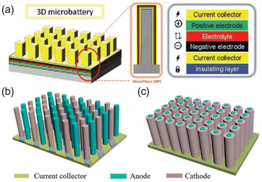 | ||
| Fig. 3 Schematic diagrams of various micro-LIBs based on 3D microstructures: (a) 3D microtube structure. Reproduced with permission from ref. 49, Copyright© 2017, Wiley-VCH Verlag. (b) 3D interlaced pillar structure and (c) 3D coaxial structure. | ||
3. Microelectrode manufacturing
3.1 Laminated thin film structure
Micro-LIBs should be compact, integrable and compatible with various microsystems. However, conventional micro-fabrication technology such as photolithography involves complex preparation processes and limited material selection and generates numerous toxic wastes when fabricating micro-LIBs. To solve these problems, great efforts were taken for developing advanced microelectrode manufacturing methods.54Several deposition technologies, including physical vapor deposition (PVD),55 pulsed laser deposition (PLD),56 chemistry vapor deposition (CVD),57 and atomic layer deposition (ALD),57–59 have been adopted to fabricate micro-LIBs with a laminated thin film structure. Among them, ALD is an effective method to manufacture high quality thin-film electrodes. ALD enables deposition of thin-films by alternating pulses of gas phase precursors into the reactor, followed by chemisorption and reaction on the deposition substrate (Fig. 4). It has the following advantages in fabrication of laminated thin film structured micro-LIBs: (i) the chemisorption of precursors onto the substrate material ensures excellent adhesion; (ii) the self-limiting nature of the surface reaction makes it possible to automate the process without the need for precise dose control and continuous operator intervention; (iii) the ordered growth processes of films provide high thickness accuracy without in situ feedback; (iv) the surface reaction ensures high conformability of the film with the matrix, regardless of whether the substrate is dense, porous, tubular, powdered or other complex shapes; (v) ALD can deposit ultra-thin and dense layers less than 1 nm with good repeatability; (vi) the surface-controlled growth characteristics make it possible to expand the throughput by increasing the batch size and substrate area.58,59
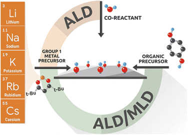 | ||
| Fig. 4 Mechanism diagram of the atomic layer deposition (ALD) technique. Reproduced with permission from ref. 58, Copyright© 2021, American Chemical Society. | ||
Besides ALD, the tape-casting technique was also employed to prepare a laminated micro-LIB jet with relatively thick films (micro-scale).60 The principle of tape-casting is that the crushed powders and organic plasticizer solution are mixed in an appropriate ratio to make a slurry with specific viscosity. Then, the scraper at a certain height makes the slurry spread on the special base tape. After drying, the base tape is peeled off to obtain a film of raw tape. Shen et al.61 prepared a porous Li7La3Zr2O12 (LLZO) solid electrolyte for micro-LIBs by using the tape-casting technique (Fig. 5a). The derived LLZO solid electrolyte (Fig. 5b) possesses the following features: (a) easy access to high porosity; (b) the pores are well arranged and the curvature is low, allowing other active materials to penetrate easily; (c) allowing scalability and environmental friendliness by using water as the solvent.
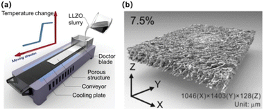 | ||
| Fig. 5 (a) Schematic diagram of the tape-casting technique. (b) Porous Li7La3Zr2O12 solid electrolyte prepared by tape-casting. Reproduced with permission from ref. 60, Copyright© 2020, American Chemical Society. | ||
Several 2D printing methods were also used to fabricate thin film micro-LIBs such as flexographic printing62 and spray printing.63 Flexographic printing is performed by using a flexible printing plate and passing ink through an anilox cylinder (Fig. 6a). The ink is first reserved in the slot located between the blade and anilox cylinder. Thereinto, the blade scrapes the anilox cylinder to ensure that the ink within the engraved cells on the anilox cylinder is uniform. Subsequently, the ink with a uniform thickness is transferred onto the flexographic printing cylinder. Wang et al. developed a LiFePO4 thin film cathode by flexographic printing (Fig. 6b).62 It may be selected for scalable battery manufacturing owing to its high production efficiency, good flexibility for printing substrates and fine resolution (20–30 μm) (Table 1). Spray printing as a traditional 2D printing technique is based on spray painting of suspended droplets atomized by a nozzle (Fig. 6c), and then the electrode structure is formed layer by layer on a heated fluid collector with a resolution of ∼40 μm (Table 1). This technology is particularly attractive for deposition of fine ink droplets via prepatterned masks onto nonplanar or curved surfaces. However, ambient humidity, temperature and surface roughness of the substrate may seriously affect the quality of the coating.
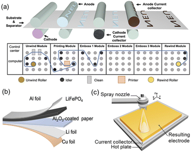 | ||
| Fig. 6 (a) Schematic diagram of flexographic printing and (b) a thin-film lithium metal battery based on the flexographic printed LiFePO4 cathode. Reproduced with permission from ref. 62, Copyright© 2022, Wiley-Blackwell. (c) Schematic diagram of spray printing for preparing thin film electrodes of LIBs. Reproduced with permission from ref. 63, Copyright© 2018, Elsevier Ltd. | ||
| Printing method | Characteristics | Resolution |
|---|---|---|
| Flexographic printing | Wide range of substrate selections, short cycle time for plate making and high production efficiency | 20–30 μm |
| Spray printing | No contact, no printing plate, allowing non-planar matrix | 40 μm |
| Screen printing | Low cost, reproducible, scalable | 50 μm |
3.2 Planar interdigital structure
For developing in-plane interdigital electrodes for micro-LIBs, screen printing is a preferable technique and has been widely investigated for preparing micro-electrochemical energy storage devices. Screen printing refers to the process of applying a prepared ink material to a custom screen stencil, and then applying sufficient pressure to allow the ink to penetrate from the screen stencil onto the underlying substrate (Fig. 7a).64–66 Zheng et al. developed MXene-LTO anode ink and MXene-LFO cathode ink for fabricating interdigital micro-LIBs by screen printing (Fig. 7b).67 The advantage of this method is that it is simple, efficient and can be applied on a large scale in real production.68 However, since the material needs to be in contact with the screen and squeegee during the printing process, it may lead to material waste and even contamination. In addition, the inks used for screen printing need to have good adsorption and rheological properties to ensure that the design is stable.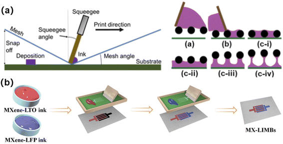 | ||
| Fig. 7 (a) Schematic diagram of screen printing. Reproduced with permission from ref. 66, Copyright© 2021, American Chemical Society. (b) A screen printed interdigital micro-LIB prepared by using MXene-based electrode inks. Reproduced with permission from ref. 67, Copyright© 2021, Wiley & Sons. | ||
3.3 3D microstructure
3D printing as a noncontact and additive manufacturing process, allows for creating complex-shaped objects with microscale resolutions and has been employed for fabricating 3D structured micro-LIBs. The most widely investigated 3D printing method for micro-LIBs focuses on the inkjet printing (IJP) and direct ink writing (DIW) methods.38,69–71IJP is based on controlling the inkjet device to print a digital image by ejecting ink droplets onto the substrate through electrical signals (Fig. 8a). The advantage of IJP is that it allows precise manufacturing of complex structures, and is also suitable for mass automated production. For IJP, the inks are generally in diluted liquid form, and are required to satisfy particular fluid behavior. Attention needs to be paid to the surface tension and viscosity of the ink, otherwise, it leads to easy agglomeration and clogging of the nozzle during printing.72,73 Compared with IJP, the DIW process is much less challenging for printing full batteries, since it allows for high loading of electrode active materials per printing pass, and the paste-like ink with shear thinning behavior is extruded, which reduces the risk of nozzle clogging. The obtained high yield stress and storage modulus of the paste-like inks contribute to the shape retention of extruded filaments (Fig. 8b). Due to the viscoelasticity of the ink, the filaments from the nozzle can be printed continuously and uniformly. The printed filaments are stacked layer by layer so that the electrodes form an 3D interdigital structure after they are freeze-dried to remove aqueous solvents.70
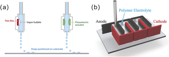 | ||
| Fig. 8 (a) Schematic diagram of inkjet printing. (b) Schematic of a DIW-printed 3D micro-LIB. Reproduced with permission from ref. 70, Copyright© 2016, WILEY-VCH Verlag GmbH & Co. | ||
The 3D holographic patterning technique combines both 3D holographic lithography and 2D photolithography, enabling the fabrication of some complex 3D microstructures. A holographically defined interdigitated 3D micro-LIB was developed by Braun's group (Fig. 9).74 3D holographic pattering was used to create the microbattery template, followed by template-assisted electrodepositions to produce thin layers of active materials that were conformally grown on 3D current collectors. The resultant microbattery consists of microscaled interdigital electrodes with mesopores and desired electrode shape. Currently, most of the 2D and 3D printing methods are still achieved in laboratories. In particular, the manufacturing of complex 3D structured microbatteries usually requires a combination of multiple techniques or cumbersome steps. There is a long way to go to realize commercial fabrication of 3D micro-LIBS with low cost, high efficiency and mass production capability.
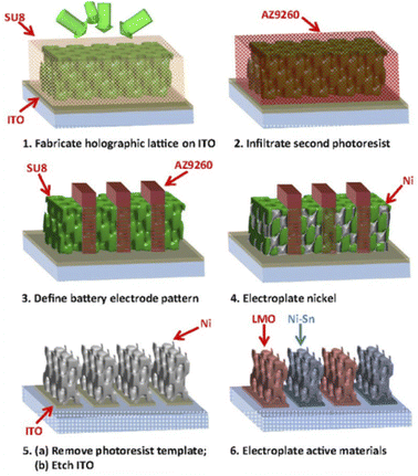 | ||
| Fig. 9 Schematic illustrations of a 3D microbattery fabricated using 3D holographic and conventional photolithographies. Reproduced with permission from ref. 74, Copyright© 2015, PNAS. | ||
4. Materials for micro-LIBs
Owing to the micro-scaled electrode sizes, the electrodes of micro-LIBs are often made of nanomaterials. Nanomaterials are beneficial to shorten the transport paths of electrons and ions, increase the contact areas between the electrode and electrolyte, and adapt to the volume change that occurs during the intercalation/deintercalation of Li+ in the electrode.75 Typical micro-LIBs reported in literature studies and their main electrochemical performances are summarized in Table 2.| Anode | Cathode | Electrolyte | Capacity | Cycling stability | Ref. | |
|---|---|---|---|---|---|---|
| a GC: graphene and CNTs. | ||||||
| Intercalation-type | Pre-lithiated CNTs | LNMO spinel | 1 M LiPF6 in EC![[thin space (1/6-em)]](https://www.rsc.org/images/entities/char_2009.gif) : :![[thin space (1/6-em)]](https://www.rsc.org/images/entities/char_2009.gif) DEC = 1 DEC = 1![[thin space (1/6-em)]](https://www.rsc.org/images/entities/char_2009.gif) : :![[thin space (1/6-em)]](https://www.rsc.org/images/entities/char_2009.gif) 1 (volume) 1 (volume) |
238 μA h cm−2 at 1C | 90% in the initial cycle | 76 |
| LTO@GCa | LFP@GC | LiTFSI-P14TFSI-PVDF-HFP | 131.4 μA h cm−2 at 50 μA cm−2 | 75.6% after 5000 cycles | 77 | |
| Carbon foam | Li foils | 1 M LiPF6 in EC![[thin space (1/6-em)]](https://www.rsc.org/images/entities/char_2009.gif) : :![[thin space (1/6-em)]](https://www.rsc.org/images/entities/char_2009.gif) DEC = 1 DEC = 1![[thin space (1/6-em)]](https://www.rsc.org/images/entities/char_2009.gif) : :![[thin space (1/6-em)]](https://www.rsc.org/images/entities/char_2009.gif) 1 (volume) 1 (volume) |
1.22 mA h cm−2 | 76% in the initial cycle | 78 | |
| TiO2 film | Li metal | 1 M LiClO4 in EC![[thin space (1/6-em)]](https://www.rsc.org/images/entities/char_2009.gif) : :![[thin space (1/6-em)]](https://www.rsc.org/images/entities/char_2009.gif) DEC = 1 DEC = 1![[thin space (1/6-em)]](https://www.rsc.org/images/entities/char_2009.gif) : :![[thin space (1/6-em)]](https://www.rsc.org/images/entities/char_2009.gif) 1 (volume) 1 (volume) |
1600 μA h cm−2 | ∼100% after 100 cycles | 79 | |
| Al2O3/Pt/Nb2O5 film | Li metal | 1 M LiClO4 in EC![[thin space (1/6-em)]](https://www.rsc.org/images/entities/char_2009.gif) : :![[thin space (1/6-em)]](https://www.rsc.org/images/entities/char_2009.gif) DMC = 1 DMC = 1![[thin space (1/6-em)]](https://www.rsc.org/images/entities/char_2009.gif) : :![[thin space (1/6-em)]](https://www.rsc.org/images/entities/char_2009.gif) 1 (volume) 1 (volume) |
8 μA h cm−2 at 1C | — | 80 | |
| Conversion-type | 3D Ni/SnOx/C | Li metal | 1 M LiPF6 in EC![[thin space (1/6-em)]](https://www.rsc.org/images/entities/char_2009.gif) : :![[thin space (1/6-em)]](https://www.rsc.org/images/entities/char_2009.gif) DEC = 1 DEC = 1![[thin space (1/6-em)]](https://www.rsc.org/images/entities/char_2009.gif) : :![[thin space (1/6-em)]](https://www.rsc.org/images/entities/char_2009.gif) 1 (volume) 1 (volume) |
1.06 mAhcm−2 at 0.1 mA cm−2 | 72% after 100 cycles | 81 |
| 3D Ni5P4 | Li metal | 1 M LiPF6 in EC![[thin space (1/6-em)]](https://www.rsc.org/images/entities/char_2009.gif) : :![[thin space (1/6-em)]](https://www.rsc.org/images/entities/char_2009.gif) DEC = 1 DEC = 1![[thin space (1/6-em)]](https://www.rsc.org/images/entities/char_2009.gif) : :![[thin space (1/6-em)]](https://www.rsc.org/images/entities/char_2009.gif) 1 (volume) 1 (volume) |
667 mA h g−1 | 80% after 100 cycles | 82 | |
| SnO2 film | Li foils | 1 M LiPF6 in EC![[thin space (1/6-em)]](https://www.rsc.org/images/entities/char_2009.gif) : :![[thin space (1/6-em)]](https://www.rsc.org/images/entities/char_2009.gif) DMC = 1 DMC = 1![[thin space (1/6-em)]](https://www.rsc.org/images/entities/char_2009.gif) : :![[thin space (1/6-em)]](https://www.rsc.org/images/entities/char_2009.gif) 1 (volume) 1 (volume) |
498.3 μA h g−1 | — | 83 | |
| Alloying-type | Si-CNT papers | Li metal | 1 M LiPF6 in EC![[thin space (1/6-em)]](https://www.rsc.org/images/entities/char_2009.gif) : :![[thin space (1/6-em)]](https://www.rsc.org/images/entities/char_2009.gif) DEC = 1 DEC = 1![[thin space (1/6-em)]](https://www.rsc.org/images/entities/char_2009.gif) : :![[thin space (1/6-em)]](https://www.rsc.org/images/entities/char_2009.gif) 1 (volume) 1 (volume) |
1000 μA h cm−2 | 97% after 1000 cycles | 84 |
| Wafer-grade monocrystalline silicon | NCA | 1 M LiClP4 in PC with 2% VC | 30 mW h cm−2 | 99.9% after 180 cycles | 85 | |
| Sn–Si composite film | Li foil | 1 M LiPF6 in EC![[thin space (1/6-em)]](https://www.rsc.org/images/entities/char_2009.gif) : :![[thin space (1/6-em)]](https://www.rsc.org/images/entities/char_2009.gif) EMC: DMC = 1 EMC: DMC = 1![[thin space (1/6-em)]](https://www.rsc.org/images/entities/char_2009.gif) : :![[thin space (1/6-em)]](https://www.rsc.org/images/entities/char_2009.gif) 1: 1 (volume) 1: 1 (volume) |
1134 mA h g−1 | 82.8% after 50 cycles | 86 | |
4.1 Materials for anodes
Similar to traditional lithium-ion batteries, the anode materials of micro-LIBs can also be divided into three categories according to the different Li+ storage mechanisms, i.e., intercalation, conversion and alloying types.Among various carbon materials, carbon nanotubes (CNTs) with a high aspect ratio, porosity and surface area were investigated as anode materials for micro-LIBs. However, the large surface area of CNTs may cause the formation of a solid electrolyte interface (SEI) layer during the initial cycle.76 The formation of a SEI layer consumes a large amount of Li+, making the initial Coulomb efficiency low. Researchers increased the Coulomb efficiency in the first cycle by immersing CNTs in 1 M LiPF6 (EC![[thin space (1/6-em)]](https://www.rsc.org/images/entities/char_2009.gif) :
:![[thin space (1/6-em)]](https://www.rsc.org/images/entities/char_2009.gif) DEC = 1
DEC = 1![[thin space (1/6-em)]](https://www.rsc.org/images/entities/char_2009.gif) :
:![[thin space (1/6-em)]](https://www.rsc.org/images/entities/char_2009.gif) 1, in volume) for pre-lithiation (Fig. 10a and b). To further improve the capacity of CNT materials, nitrogen or boron-doped CNTs were studied; however, their effects were still limited.88 It has been proved that multi-walled CNTs (MWCNTs) could achieve higher reversible capacity at higher rates than that of single-walled CNTs (SWCNTs). It is attributed to the fact that MWCNTs have larger hollow cores (10–20 nm) that could facilitate the diffusion of lithium ions into the internal cores of MWCNTs and reduce the Li+ intercalation/deintercalation potential.89 Based on this fact, Ren et al. used MWCNT-fibers and lithium wires as anodes to obtain wire-shaped micro-LIBs (Fig. 10c).88 They further infiltrated MnO2 nanoparticles into MWCNT-fibers to enhance the energy density of cells, and obtained a discharging energy density of 35.74 mW h cm−3 at 2 × 10⁻³ mA.
1, in volume) for pre-lithiation (Fig. 10a and b). To further improve the capacity of CNT materials, nitrogen or boron-doped CNTs were studied; however, their effects were still limited.88 It has been proved that multi-walled CNTs (MWCNTs) could achieve higher reversible capacity at higher rates than that of single-walled CNTs (SWCNTs). It is attributed to the fact that MWCNTs have larger hollow cores (10–20 nm) that could facilitate the diffusion of lithium ions into the internal cores of MWCNTs and reduce the Li+ intercalation/deintercalation potential.89 Based on this fact, Ren et al. used MWCNT-fibers and lithium wires as anodes to obtain wire-shaped micro-LIBs (Fig. 10c).88 They further infiltrated MnO2 nanoparticles into MWCNT-fibers to enhance the energy density of cells, and obtained a discharging energy density of 35.74 mW h cm−3 at 2 × 10⁻³ mA.
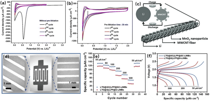 | ||
| Fig. 10 Cyclic voltammograms of pre-lithiated CNTs for (a) 0 min and (b) 30 min. Reproduced with permission from ref. 76, Copyright© 2020, by the authors. (c) Schematic diagram of a wire-shaped micro-LIB composed of lithium wire and MWCNTs. Reproduced with permission from ref. 88, Copyright© 2013, WILEY-VCH GmbH. (d) An interdigital LTO@GC‖LFP@GC micro-LIB and the corresponding enlarged images of microelectrodes patterns. (e) Rate performance and (f) GCD profiles of the LTO@GC‖LFP@GC micro-LIB. Reproduced with permission from ref. 77, Copyright© 2021, Wiley-VCH GmbH. | ||
In addition to carbon-based materials, lithium titanate (LTO) is also a promising anode material. LTO has an excellent chemical stability and long cycle life, due to its stable and dense structure. In an LTO crystal, 3/4 of the total lithium ions are embedded in the void by four oxygen ions in close proximity as positive tetrahedral ligands, while the remaining lithium ions and all titanium ions are embedded in the void by six oxygen ions in close proximity as positive octahedral ligands. Such a structure provides access to Li+ and allows LTO to have a small volume change (<1%) during Li+ intercalation/deintercalation. However, LTO has poor conductivity and severe polarization when discharged at high currents. Wu's group made a printable anode ink by mixing conductive additives of graphene and CNTs with LTO (LTO@GC) for screen printing (Fig. 10d).77 CNTs and graphene build a 3D conductive network that facilitates the rapid conduction of lithium ions and electrons, improving the total conductivity of the electrode material. They prepared a micro-LIB using LiTFSI-P14TFSI-PVDF-HFP as the electrolyte and LFP@GC as the cathode, and compared it with a full cell composed of LTO and LFP with only graphite as the conducting additive (LTO@G and LFP@G) at different current densities. LTO@GC‖LFP@GC showed an areal capacity of 49.4 μA h cm−2 at a current density of 500 μA cm−2, and good rate performance (Fig. 10e). Moreover, due to the 3D conductive framework of CNTs and graphene, electrons and Li+ can be transported rapidly, allowing the LTO@GC‖LFP@GC micro-LIB to have a higher voltage plateau and lower voltage polarization at high current densities (Fig. 10f).
The conversion-type anode materials for micro-LIBs reported so far mainly include tin oxide and tin nitride.83,92 Compared with tin oxide, tin nitride has a higher first-round Coulomb efficiency, and is stable at room temperature in air.82 Park et al. deposited tin nitride films on a Pt/Ti/SiO2/Si matrix by using radio frequency (RF) magnetron sputtering.92 They found that the films obtained by deposition at different temperatures showed different discharge capacities. The discharge capacity gradually increased with the increase in deposition temperature. Such a phenomenon was attributed to the densification of the films and resulted in the production of a large amount of active material.
Researchers demonstrated that 3D structured electrodes can increase the areal capacity of micro-LIBs. The 3D framework serves promisingly as an effective channel for electron transport and Li+ diffusion, and adapts to the large volume change during lithiation/delithiation.81 Tin oxide (SnO2) has a theoretical specific capacity of 781 mA h g−1, which is twice the capacity of conventional graphite. Zhu et al. obtained a 3D Ni/SnOx/C network electrode by growing SnOx on Ni2(OH)2CO3 nanowall arrays, and coating them with glucose molecules, followed by annealing and reduction (Fig. 11a).81 It was found that compared with SnOx/C, 3D Ni/SnOx/C possesses better rate performance and lower resistance (Fig. 11b and c). It is due to the fact that the 3D Ni framework provides good diffusion channels for Li+ and electrons. However, the precise control of the phase composition and 3D nanostructure simultaneously remains a challenge. Belcher's team used M13 bacteriophages as biological scaffolds to control a range of phase composition and structural elements.82 The derived 3D Ni5P4 nanofoams were integrated into micro-LIBs, exhibiting a specific capacity up to 677 mA h g−1 and good cycling performance. They also demonstrated that this synthetic approach could be applied to precisely control the 3D nanostructure and phase composition of metal phosphides, such as cobalt and copper phosphides.
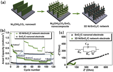 | ||
| Fig. 11 (a) Fabrication process, (b) rate performance and (c) EIS plot of the 3D Ni/SnOx/C electrode. Reproduced with permission from ref. 81, Copyright© 2013, American Chemical Society. | ||
To address the above issues, researchers investigated the volume change mechanism of silicon. They concluded that the formation of Li15Si4 was responsible for the degraded cycling properties of the Si anode. The alloying process of Li+ and Si involves two steps: (i) in the first Li+ intercalation process, crystalline Si and Li+ combine and transform into amorphous lithium silicide; (ii) the amorphous lithium silicide further transforms into crystalline Li15Si4 in the subsequent Li+ stripping process. The large amount of Li+ intercalation, complex phase transition of LixSi and enthalpy loss caused by the phase transition lead to serious volume expansion (nearly 300%) and structural change of the silicon anode. Such a huge volume change may lead to cracks and pulverization of Si particles. Moreover, the SEI layer on the surface of Si particles bursts due to the volume expansion of Si, which makes Si react with electrolyte continuously, resulting in continuous consumption of active lithium and eventually, in capacity loss.84,85 Sternad's group prepared micro-LIBs by using wafer-scale monocrystalline Si with a thickness of 50 μm as the anode (Fig. 12a).85 This thickness of monocrystalline Si could effectively transport Li+ from the surface to the interior of the block. It facilitated reducing the surface lithium concentration and thereby inhibiting the formation of Li15Si4. Thus, the cycling stability of the Si anode was improved. Moreover, owing to surface lithiation, surface stresses created cracks in the 〈110〉 direction of Si. Such a phenomenon allowed secondary lithiation of Li+ within Si, and enabled overall activation of the material and increase of energy density (Fig. 12b).
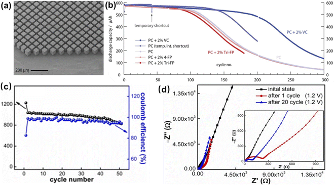 | ||
| Fig. 12 (a) The anode compartment of a microbattery based on monocrystalline Si, and (b) cycling tests of the microbattery made of monocrystalline Si in different electrolytes. Reproduced with permission from ref. 85, Copyright© 2021, by the authors. (c) Cycling performance and (d) EIS plots of a Sn–Si anode. Reproduced with permission from ref. 86, Copyright© 2021, by the authors. | ||
Researchers also proposed carbon and tin-modified silicon to mitigate its volume change.94 Biserni et al. deposited a nanostructured porous amorphous Si film on flexible CNT paper by PLD at room temperature, and obtained a Si–C nanocomposite by CVD of a thin carbon coating on the film as the anode.80 In this nanocomposite, the meso-porosity and lack of crystallinity of the nanostructured Si films can prevent the mechanical stress induced by amorphization of Si in the first cycle. The thin carbon layer is beneficial to promote the formation of a stable SEI layer and prevent Si coming into contact with the electrolyte which reacts and consumes Si during cycling. Moreover, CNTs provide a porous substrate that provides enough space for the volume expansion of Si. A cycling test by assembling micro-LIBs revealed that only 3% of capacity was lost after 1000 cycles at a current density of 1080 μA cm−2. The charge/discharge curves showed two plateaus, which were thought to be due to the formation of the SEI layer and lithiation of amorphous Si.90
In addition to composites with carbon materials, the introduction of electrochemically active substances (such as Sn, Sb and Ge) into non-conductive silicon to enhance its electrical conductivity and mitigate its volume change was also proposed. Among them, Sn–Si composites have received attention due to the high conductivity, good ductility of Sn and the high capacity of Si. Ma et al. synthesized a Sn–Si composite film anode by co-sputtering.86 Its inherent phase separation structure could buffer the volume change during alloying/de-alloying. Sn particles can increase ionic conductivity and improve Li+ transport, while Si as a buffer matrix can inhibit the growth of Sn grains, reduce structural damage and enhance cycling performance (Fig. 12c and d).
4.2 Materials for cathodes
The cathode active materials for micro-LIBs should have a high redox potential, stable structure, good conductivity, and high chemical and thermal stabilities. Among them, lithium iron phosphate [LiFe(PO4)3, LFP] received much attention due to its acceptable capacity (170 mA h g−1), flat discharge potential (about 3.4 V), high safety and cycling stability.95,96LFP has an olivine structure, where Fe and Li are located in the center of oxygen atom octahedra, respectively, forming FeO6 and LiO6 octahedra. The adjacent LiO6 are connected by oxygen atoms to form a continuous linear chain of Li+, which enables Li+ to diffuse. Moreover, the oxygen ions combine with P5+ by strong covalent bonds to form phosphate, where O is difficult to be removed, thus improving the stability of the material.97 When Li+ is removed from LFP, LFP is transformed into FePO4 with only 6.81% volume reduction and 2.59% density increase. When paired with a carbon anode, the overall battery volume changes very little during cycling, ensuring good charge/discharge stability of the cell.96–98 However, the poor electronic conductivity of LFP leads to obvious initial capacity loss and poor rate performance.99
Producing LFP cathode with thin film structure may solve the above problems by taking advantage of the shorter ion transport paths and close contact interface of thin-film cells.95 Sugiawati et al. successfully obtained porous LFP films by RF sputtering with post-annealing at 500 °C. They found that if the annealing temperature was increased to 700 °C, the olivine structure could be transformed into a NASICON-type [Li3Fe2(PO4)3] structure. This structure has good ion mobility and can insert up to 2 mol of Li with a theoretical capacity of 128 mA h g−1. NASICON-type LFP is more stable and has better rate and cycling capability than olivine-type LFP (Fig. 13a and b).
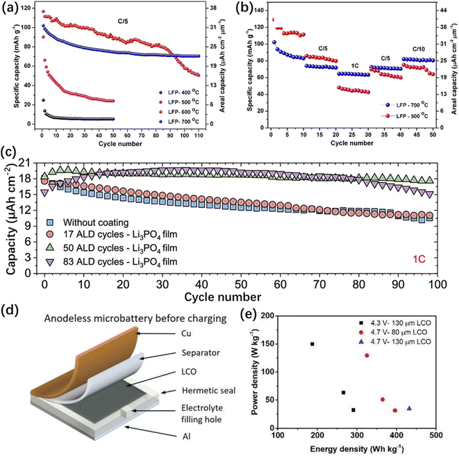 | ||
| Fig. 13 (a) Cycling performance and (b) rate performance of the olivine-type LFP cathode. Reproduced with permission from ref. 95, Copyright© 2019, by the authors. (c) Cycling performance of the LMNO film cathode. Reproduced with permission from ref. 102, Copyright© 2021 American Chemical Society. (d) Schematic illustration of the anode-less microbattery structure before charging. (e) Energy density and power density of LCO cathodes with different thicknesses at different working voltages. Reproduced with permission from ref. 103, Copyright© 2021, Wiley-VCH GmbH. | ||
Although LFP has good chemical and thermal stabilities, its specific capacity is limited. Researchers found that Li-rich layered oxide spinel LiMn1.5Ni0.5O4 (LMNO) has a capacity higher than 250 mA h g−1 and can also provide excess capacity beyond its theoretical capacity based on cationic redox processes. In Li-rich oxides, the charge loss caused by Li+ migration is balanced by the oxidation of O2− to O2, which is manifested by the reaction of free Li+ in the electrolyte with oxygen to form Li2O, producing a net loss of LiO2. On the one hand, the net loss of LiO2 makes the average oxidation state of the transition metal lower at the end of charging, and a higher reversible capacity is obtained in subsequent cycles; on the other hand, the loss of LiO2 causes an irreversible decrease in the amount of Li+ in the material, and the irreversible release of oxygen also reduces the binding energy of transition metal ions to oxygen, causing an irreversible phase transition in the material. This phenomenon leads to a significant decrease of capacity in the first cycle.100
To solve this problem, researchers investigated the chemical structure of LMNO. It was found that LMNO can be crystallized into two crystal structures, namely, an ordered spinel structure and spinel-free structure. Among them, micro-LIBs made with disordered spinel LMNO films have longer cycle life and higher electrical conductivity. It is caused by the higher electron conductivity between the mixed Mn3+ and Mn4+ in the disordered structure than the pure Mn4+ in the ordered structure.101 However, due to the higher redox potential of LMNO (∼4.7 V), it may react with the electrolyte, generate an SEI layer and then reduce the capacity of the cell. It was proposed that coating a nano-layer of metal oxide or phosphate (ZnO, ZrO2, AlPO4 or Li3PO4) on the surface of the LMNO film could reduce the capacity loss. Hallot et al. coated LMNO with Li3PO4 by ALD, and found that the coating could well prevent the electrolyte from reacting with LMNO. It greatly improved the first coulombic efficiency as well as the cycling stability of the cell (Fig. 13c).102
In addition to LFP and LMNO, lithium cobaltate (LCO) was also applied as cathode material for micro-LIBs due to its high operating voltage, high specific capacity, smooth discharge and good cycling performance.103 LCO has two crystal structures: a hexagonal laminate structure and cubic spinel structure. Cubic spinel-type LCO has low loose packing density and poor electrochemical performance, so it is rarely used. In hexagonal layered LCO, Li+ can easily be transported in the two-dimensional channel of the O–Li–O layer. Yue et al. prepared a LCO cathode for micro-LIBs by plating crystal-oriented LCO onto a thin metal foil (Fig. 13d).103 The micro-LIB can be charged to 4.7 V to achieve energy densities of 432 W h kg−1 and 1055 W h L−1 (Fig. 13e). However, the LCO cathode cannot be charged above 4.7 V due to the phase transition when Li+ is delithiated from LCO. The structure of LCO is stable when the amount of Li+ removed is 0–50%, and the corresponding cut-off voltage is 4.7 V. However, if Li+ removal continues, LCO with a hexagonal laminar structure will transform into a monoclinic structure, which affects the cycling stability of the material and aggravates the capacity loss.
The common methods to improve the performance of LCO involve coating and bulk phase doping. It is easy for LCO to react with the electrolyte, leading to the generation of harmful interface phases. Such a phenomenon causes a decrease in the conductivity and Li+ depletion, and thus capacity reduction. Coating a thin interface layer (such as a thin Al2O3 or TiO2 layer) on the surface of LCO could separate the electrode material from the electrolyte, and thus effectively suppress interface side reactions.104,105 Doping metal elements into LCO has the following benefits: (i) increasing the specific capacity and energy density of the cathode material; (ii) improving material stability and cycling performance; (iii) reducing the use of expensive cobalt metal and lowering the cost. Chen et al. demonstrated that doping Al and Nb/W into Co sites and Li sites into LCO, respectively, can suppress the unfavourable phase transition of LCO under high pressure, increase the interlayer spacing of the LCO structure, and achieve rapid Li+ diffusion. It was found that at a voltage of 4.7 V and a current density of 10 C, the battery could still maintain 60.4% of its reversible capacity after 1000 cycles. This research guided the design of micro-LIBs with high working voltages.106
4.3 Materials for electrolytes
Electrolytes have the role of transporting ions and conducting current between the positive and negative electrodes, which are generally classified as liquid electrolytes and solid electrolytes. Liquid electrolytes have the advantages of good ionic conductivity and close interface contact with electrodes. Liquid electrolytes are generally composed of organic solvents, lithium salts and additives. The common organic solvents used for micro-LIBs are ethylene carbonate (EC), diethyl carbonate (DEC), and dimethyl carbonate (DMC); the electrolyte lithium salts include lithium hexafluorophosphate (LiPF6) and lithium perchlorate (LiClO4). The electrolyte with LiClO4 as lithium salt has the following advantages in comparison with other electrolytes: high conductivity, stable composition, low cost and easy purification. However, since LiClO4 is a strong oxidizer, it easily reacts with organic solvents at a high voltage and give rise to safety risks. LiPF6 has the advantages of high conductivity, high solubility and antioxidant capacity. However, its thermal decomposition temperature is low (30 °C), and it is easily decomposed into PF5 and LiF. In the preparation of micro-LIBs, liquid electrolytes share a common disadvantage: leakage and encapsulation difficulties. Therefore, solid electrolytes have great potential in the field of micro-LIBs.To apply solid electrolytes in micro-LIBs, the following conditions need to be met: (a) high ionic conductivity at the device operating temperature; (b) high electrochemical and thermal stability in contact with electrode materials; (c) high mechanical strength to prevent the emergence and growth of lithium dendrites; (d) low-cost mass production and (e) low toxicity.107–112 At present, solid electrolytes are generally classified into three categories: inorganic crystal electrolytes, inorganic glass electrolytes and polymer-based solid electrolytes.
Polymer electrolytes (PEs) have good ionic conductivity, flexibility, adaptability to the volume change of the electrode, and adjustable mechanical strength to prevent lithium dendrite growth.113 PEs are generally obtained by dissolving lithium salts (such as LiPF6, LiTFSI and LiDFOB) in the polymer matrix, such as polyethylene oxide (PEO), poly (methyl methacrylate) (PMMA), and polyvinylidene fluoride (PVDF).107 Compared with other solid electrolytes, PEs are able to reach the tiny space between the electrodes of micro-LIBs, and provide good contacts between electrolyte and electrodes. PEs can be further classified as solid polymer electrolytes, composite polymer electrolytes and gel polymer electrolytes. Solid polymer electrolytes (SPE) do not use organic liquids in the system, and thus have relatively low ionic conductivity at room temperature. Composite polymer electrolytes are a special class of SPEs, whose polymers can be blended, cross-linked, doped, and enhanced by additives and inorganic fillers. Gel polymer electrolytes (GPE) generally consist of a polymer matrix and a liquid component (typically organic electrolytes). The liquid component in GPE increases ionic conductivity and interfacial stability, while the polymer matrix provides sufficient mechanical strength and flexibility. The polymers in GPEs are plasticized and swollen by the liquid electrolyte, so they are also called plasticized PEs.114–120
Chaudoy et al. prepared a GPE for thin film micro-LIBs using a mixture of polyvinylidene fluoride-co-hexafluoropropylene (PVDF-HFP), cross-linked polyethylene oxide (PEO) and an ionic liquid.121 In this electrolyte, PVDF-HFP helps to increase the pore size and porosity of the electrolyte membrane, and then to improve ion transport (Fig. 14a). The cross-linked PEO can form a semi-interpenetrating polymer network (semi-IPN) with PVDF-HFP, which has the ability to retain the liquid phase and boost mechanical strength to prevent dendrite growth (Fig. 14b). It was confirmed that positively charged surface of inorganic materials with oxygen vacancies can strongly interact with the anions of electrolyte salts, releasing more Li+ and increasing ionic conductivity.122,123 Based on this principle, Chen et al. added Ca-doped CeO2 (Ca–CeO2) nanotubes with oxygen vacancy-rich surfaces into PEO-based polymer electrolyte for micro-LIBs.123 Ca–CeO2 nanotubes can provide ion transport channels, and the hollow structure increases the contact area with PEO-based electrolyte. Both factors are favourable to promote the Li+ migration number, so that Li+ can be deposited uniformly during cycling and prevent the growth of lithium dendrites (Fig. 14c).123
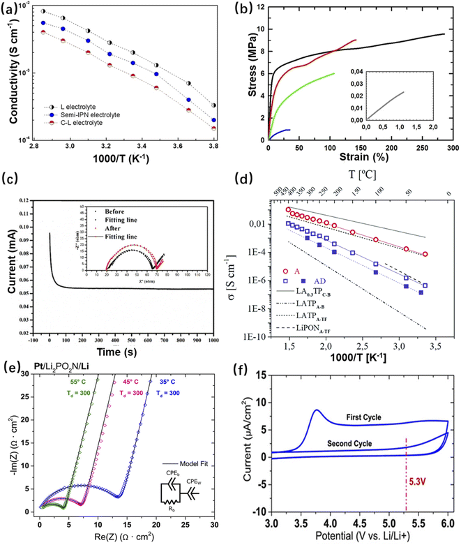 | ||
| Fig. 14 (a) Plot of semi-IPN electrolyte conductivity versus temperature (blue colour), and (b) static tensile tests for the electrolyte matrices without liquid encapsulation based on the following compositions: only PVdF-HFP (black), 75 wt% PVdF-HFP/25 wt% POE (red), 50 wt% PVdF-HFP/50 wt% POE (green), 25 wt% PVdF-HFP/75 wt% POE (blue), and only POE (grey). Reproduced with permission from ref. 121, Copyright© 2021, Wiley-VCH GmbH. (c) Chronoamperometry curve of the PEO/LiTFSI/10Ca–CeO2 film at a potential step of 10 mV at 60 °C. Reproduced with permission from ref. 123, Copyright© 2020, WILEY-VCH Verlag GmbH & Co. (d) Arrhenius plots under different annealing conditions for LATP thin films deposited on a Si3N4 substrate by PLD, and their corresponding activation energies and conductivities (AD for as-deposited and A for post-annealed). Reproduced with permission from ref. 128, Copyright© 2021, The Royal Society of Chemistry. (e) EIS tests and (f) cyclic voltammetry curves of the Pt/Li2PO2N/Li half-cell. Reproduced with permission from ref. 130, Copyright© 2017, American Chemical Society. | ||
Inorganic crystalline electrolytes tend to have high ionic conductivity, thermal stability and electrochemical decomposition potential. However, the presence of grain boundaries in inorganic crystalline electrolytes can lead to impeded Li+ transport. Therefore, to obtain a relatively high total conductivity, a good contact between the electrolyte and electrode is required.118 The most studied inorganic crystalline electrolytes include NASICON,111 LISICON,124 perovskite,125 and garnet-type electrolytes.126,127 As a third-generation oxide solid electrolyte with a NASICON crystal structure, lithium titanium phosphate [LiTi2(PO4)3] has an ionic conductivity of 2 × 10⁻⁶ S cm−1 at room temperature. By further doping the raw material with Al2O3, Li1.3Al0.3Ti1.7(PO4)3 (LATP) was obtained, which allowed Al3+ to partially replace Ti4+. Due to the doping of Al3+, Li+ can occupy additional interstitial positions, which further enhances its ionic conductivity. Tarancon's team fabricated LATP thin films as a solid electrolyte for micro-LIBs by the PLD technique, which achieved an ionic conductivity up to 10−4 S cm−1 after annealing (Fig. 14d).128
Inorganic glass electrolytes have certain structural advantages over crystalline electrolytes. For example, with highly defective structures, inorganic glassy electrolytes have ample empty spaces for Li+ to occupy, which are beneficial for ion migration. They can vary continuously in composition, which implies chemical diversity. Moreover, glassy materials are isotropic with ions diffusing in the same path in all directions, which makes it easier for ions to pass through the particle interface. Among the existing glass electrolytes, LiPON has relatively high ionic conductivity, low electronic conductivity and excellent electrochemical stability. The general formula of LiPON is LixPOyNz (x = 2y + 3z − 5).129 LiPON was also made into thin film electrolytes for micro-LIBs. Pearse et al. used ALD to fabricate Pt/Li2PO2N/Li half-cells for EIS testing, and the results are shown in Fig. 14e. It can be seen that the electrical conductivity is greatly improved in comparison with the conventional LiPON electrolyte. Moreover, the thin film is believed to prevent surface degradation of electrode materials and increase electrochemical stability.130 The electrochemical stability of LiPON electrolyte was tested by cyclic voltammetry (Fig. 14f). It was found that in the first cycle, there was a small anodic peak at 3.8 V, which indicated that a slight reaction occurred. However, in the second cycle, no reaction occurred at 3.8 V, which was believed to be due to the formation of a self-limiting SEI layer on the electrode, so that the electrolyte remained stable in the voltage range of 0–5.3 V.
4.4 Materials for current collectors
The current collector plays a role in supporting the electrode material and connecting the internal and external circuits. For micro-LIBs, conventional Cu or Al inks are not suitable for use as current collectors because surface oxidation disrupts electron injection behaviour. The current collector layers were generally fabricated by multiple deposition technologies, such as vacuum vapor deposition, PVD and PLD. For planar interdigital and 3D structured micro-LIBs, freestanding aluminium, copper and nickel nanorod arrays, high aspect ratio 3D carbon structures, and porous Ni, Au and Pt have been reported.89,131–134Among them, 3D metal current collectors based on nanorod arrays (such as an Al nanorod array, Fig. 15a) obtained by constant current and pulsed current electrodeposition presented a high specific surface area and improved rate performance.131 A porous 3D Ni current collector (Fig. 15b) with high specific surface area could reduce the local current density during lithium deposition and slow down the growth of lithium dendrites.89,132 However, it is difficult to manufacture the above two kinds of 3D current collectors. Researchers are looking for 3D current collectors that can be easily manufactured. Yuan et al. proposed the method of orthogonal ploughing and extrusion to prepare a 3D structure on a copper plate (Fig. 15c).134 This method avoids the introduction of additional layers or components, and provides rich surface morphology. The grooves and cavities on the surface of the current collector are conducive to the improvement of the reversible specific capacity and rate performance of on-chip LIBs (Fig. 15d and e). To realize interdigital micro-LIBs, low cost, highly conductive and printable current collector inks with high operational voltage are urgently required. However, the reported printed current collectors for interdigital micro-LIBs are very limited until now.
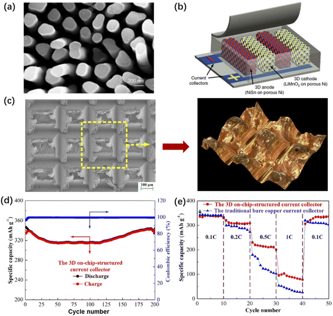 | ||
| Fig. 15 (a) SEM image of a 3D metal current collector based on an aluminium nanorod array. Reproduced with permission from ref. 131, Copyright© 2015, Elsevier B.V. (b) Structural diagram of a porous nickel current collector for micro-LIBs. Reproduced with permission from ref. 132, Copyright© 2021, Science Press and Dalian Institute of Chemical Physics, Chinese Academy of Sciences. (c) SEM image and optical image of a 3D copper current collector. (d) Cycling performance and (e) rate performance of the micro-LIB based on a 3D Cu current collector. Reproduced with permission from ref. 134, Copyright© 2019, American Chemical Society. | ||
5. On-chip integrated microsystems
The ultimate goal of investigating micro-LIBs is to realize their on-chip integration with microelectronic systems, so as to achieve target-oriented functions. Up to now, micro-LIBs integrated with energy harvesters, light-emitting diodes, sensors, etc., have been studied.The combination of micro-LIBs with miniaturized energy harvesting devices (such as solar cells,135 triboelectric nanogenerators,136 electrostatic nanogenerators137 or their hybrids138) enable on-chip self-powered systems. Wang et al. developed a photo-rechargeable micro-LIB using γ-LiV2O5 material as the cathode without using any photo-absorption and charge-separation agents (Fig. 16a). The device could collect solar energy and convert it into electrical energy for storage. The self-powered microsystem can be effective because the band gap width of γ-LiV2O5 is 2.8 eV, which is exactly in the visible light energy range and thus can absorb visible light.135 A triboelectric nanogenerator (TENG) as one of the mechanical energy harvesters, can be used to collect human mechanical energy. Wang’s group developed a self-powered microsystem by integrating a TENG and an electromagnetic generator (EMG) with a Li-ion battery (Fig. 16b). The harvested electric energy after 100 cycles of vibration could charge a lithium battery from 2.62 to 3.06 V after 30 min.136 Yang's group demonstrated a convoluted power device by internally hybridizing a solid-state Li-ion battery (SLB) and a TENG via sharing common electrodes (Fig. 16c). The TiO2 nanotubes and the LMO film were utilized as the anode and cathode of the SLB, respectively. The working of the TENG is based on the coupling between the triboelectric effect and electrostatic induction under periodical contact/separation between TiO2 nanotubes and the FEP film. The device can be mounted on a human shoe, thus demonstrating potential for self-powered wearable electronics. A third type of self-powered microsystem is a combination of the above two types of energy harvesters that collects solar energy as well as mechanical energy. Ma et al. designed a class of such a hybrid self-powered microsystem, in which solar cells and TENGs were integrated with micro-LIBs simultaneously (Fig. 16d).138 Such a combination plays a compensating role in realizing uninterrupted energy harvesting.
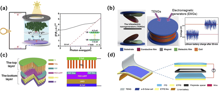 | ||
| Fig. 16 (a) Schematic diagram of a photo-rechargeable micro-LIB. Reproduced with permission from ref. 135, Copyright© 2022, American Chemical Society. (b) An energy device integrated by using TENGs and EMGs to charge a lithium battery. Reproduced with permission from ref. 136, Copyright© 2018, Tsinghua University Press. (c) Schematic diagram of a self-powered system integrated by using an electrostatic nanogenerator and a solid-state micro-LIB. Reproduced with permission from ref. 137, Copyright© 2017, Wiley-VCH Verlag. (d) Schematic diagram of a hybrid self-powered microsystem. Reproduced with permission from ref. 138, Copyright© 2019, Elsevier B.V. | ||
Furthermore, Liu et al. integrated a green light-emitting diode (LED) into a self-powered microsystem constructed with micro-LIBs and a TENG (Fig. 17a). The self-powered microsystem can continuously provide energy for the green LED.137 Micro-LIBs can also be integrated with various sensors to realize wireless sensing, smart detection and other functions. Toor et al. assembled a micro-electro-mechanical system (MEMS)-based wireless sensor device, and demonstrated the effectiveness of a micro-LIB as a power source for the integrated electronic device (Fig. 17b).139 Moreover, Gao et al. designed a smart light-working microcontroller unit (Fig. 17c),140 which was composed of a magnetic sensor array, a microprocessor, a light emitting device and detection circuits, for smart public safety detection. A smart public safety sensing system with low-cost, small-size and low-power properties can help to promote the development of smart city public safety networks, and is also expected to promote multiple smart lighting devices into wireless networks for mass monitoring. With further development in materials, component structures, device fabrications and system integration, in the near future, micro-LIBs with a high degree of customizability would be extensively explored for smart microsystems to achieve more customized function prototypes, such as self-healing, shape-memory, load-bearing, electrochromism, photodetection, etc.
 | ||
| Fig. 17 (a) Photograph of a green light-emitting diode lit by a self-powered microsystem. Reproduced with permission from ref. 137, Copyright© 2017, Wiley-VCH Verlag. (b) Schematic diagram of a wireless sensor and a micro-LIB integrated device. Reproduced with permission from ref. 139, Copyright© 2021, Elsevier B.V. (c) Photograph of a smart light-working microcontroller unit. | ||
6. Challenges and perspectives
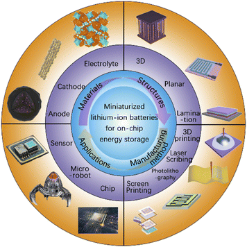
Micro-LIBs are expected to play an irreplaceable role as on-chip power supplies for miniaturized electronic devices and microsystems. More and more scientists have devoted themselves to develop novel materials, advanced cell architectures, and economic manufacturing technologies, and further improve the electrochemical performances, durability and practicability of micro-LIBs (Fig. 18). In this review, the developments of micro-LIBs in recent years are systematically introduced. We simply give an introduction about the concept and features of micro-LIBs, such as ultra-compactness, light weight, easy integration and good electrochemical performances. Meanwhile, the microstructure design of micro-LIBs including a laminated thin film structure, a planar interdigital structure, a 3D interdigital structure and other types of 3D architectures, are emphasized. Following this, we summarize the microelectrode manufacturing methods of micro-LIBs. Within this discussion, the microelectrode manufacturing methods for each microstructure configuration are introduced. Materials considerations for micro-LIBs are specifically discussed. Last but not least, on-chip integrated microsystems with various functions which exhibit particular advantages of micro-LIBs in various application scenarios are mentioned.Despite the ever-increasing development of micro-LIBs, several challenges prevent them from becoming a mature technology until now. Firstly, to improve the electrochemical performances and develop next generation micro-LIBs, advanced electrolytes should be carefully taken into consideration. At present, liquid organic electrolytes are the most common electrolytes used in micro-LIBs due to their high ionic conductivities. However, the problems of electrolyte leakage and cell encapsulation for steady operation urgently need to be solved. Therefore, solid electrolytes with the properties of high safety, low self-discharge and being easy to package should be further studied and employed in micro-LIBs. Among them, solid polymer electrolytes with advantages of superior processing flexibility, great electrode–electrolyte interfacial contact and adjustable mechanical properties have the most practical prospect in commercial applications.
Secondly, to achieve the widespread application of micro-LIBs in functional microsystems, it is urgent to develop advanced microelectrode manufacturing methods, which are easy-to-operate, eco-friendly, and have low-cost and high-efficiency. As yet, various microelectrode manufacturing methods have been reported for micro-LIBs, including but not limited to 3D printing, photolithography, laser scribing, electrodeposition, transfer printing and mask-assisted filtration. However, most of these microelectrode manufacturing methods are only realized in the laboratory and cannot satisfy the requirements of commercialization. 3D printing is considered as the most promising technology for on-chip manufacturing of micro-LIBs. The greatest advantage of 3D printing is that it can directly print the solid polymer electrolyte and allows in situ encapsulation of the microsystem. Moreover, 3D printing has the capability to manufacture various shapes and structures of micro-LIBs, which contributes to a great future for flexible and customized manufacturing.
Thirdly, further shrinking the size of micro-LIBs to obtain high compactness is required. At present, the miniaturization of reported micro-LIBs is not good enough for a variety of reasons, including the large particle sizes of active materials and limitations of manufacturing technologies. When using liquid electrolytes, encapsulating the liquid electrolytes and other parts of micro-LIBs on-chip without electrolyte leakage and being compatible with other microelectronic components is a significant technical difficulty. A possible method reported to package micro-LIBs is by using specific curable polymers (such as polydimethylsiloxane) by light-curing or heat-curing.
Fourthly, developing advanced electrode materials, adjusting the specific parameters of the microelectrodes and configuring a preferable 3D microstructure to improve the specific surface area, mass loading and conductivity of active materials, and then promoting the energy density, power density and cycle life of micro-LIBs should be further studied. For example, emerging hybrid-type anode materials such as alloy-intercalation-type (SnS2/CNTs)141 and conversion-alloy-type (Sb2S3)142 anode materials could also be studied in micro-LIBs to improve the energy densities of cells, owing to their high theoretical capacities and relatively low operating voltages.143–145 In addition, it is important to explore in situ and semi-in situ characterization techniques (such as in situ X-ray diffraction, neutron diffraction, in situ conductive atomic force microscopy, nuclear magnetic resonance, cryo-electron microscopy, etc.), which can monitor real-time changes and provide important structural and electrochemical information for performance analysis of micro-LIBs. High-resolution characterization techniques play an important role in exploring battery evolution and ion transport mechanisms during the charging/discharging process. By analyzing the ion transport and cycling degradation mechanisms of micro-LIBs through modelling/simulation, the design parameters of cells can be systematically analyzed and the cell structure can be optimized, so as to shorten the development cycle and reduce research cost of micro-LIBs.
Finally, we should also focus on the integration of micro-LIBs into microsystems to realize more novel functions, for example, self-healing, shape-memory, electrochromism, photodetection, etc. Nowadays, some devices such as wireless sensors and microcontroller unit systems have made use of micro-LIBs, and we believe that more and more practical tools will be invented with micro-LIBs. Next generation smart electronics such as implanted devices, wearable devices and microrobots will be highly customizable, which reflect improvement not only in shape and flexibility, but also in functions. A variety of microsystems will come up to meet the urgent demands. As a conclusion, microelectronics with advanced materials, ingenious microstructures and integrated systems will play a significant role in human society. We should grasp the opportunity, create next generation micro-LIBs and pave the way for the further development of intelligent electronic products.
Conflicts of interest
There are no conflicts to declare.Acknowledgements
We appreciate the support from the College Students' Innovative Entrepreneurial Training Plan Program of the Huazhong University of Science and Technology (CL2022025).References
- S. Ferrari, M. Loveridge, S. D. Beattie, M. Jahn, R. J. Dashwood and R. Bhagat, Latest advances in the manufacturing of 3D rechargeable lithium microbatteries, J. Power Sources, 2015, 286, 25–46 CrossRef CAS.
- W. Li, T. L. Christiansen, C. Li, Y. Zhou, H. Fei, A. Mamakhel, B. B. Iversen and J. J. Watkins, High-power lithium-ion microbatteries from imprinted 3D electrodes of sub-10 nm LiMn2O4/Li4Ti5O12 nanocrystals and a copolymer gel electrolyte, Nano Energy, 2018, 52, 431–440 CrossRef CAS.
- M. Nathan, D. Golodnitsky, V. Yufit, E. Strauss, T. Ripenbein, I. Shechtman, S. Menkin and E. Peled, Three-dimensional thin-film Li-ion microbatteries for autonomous MEMS, J. Microelectromech. Syst., 2005, 14, 879–885 CAS.
- Z. Lei, J. Zhang, L. L. Zhang, N. A. Kumar and X. S. Zhao, Functionalization of chemically derived graphene for improving its electrocapacitive energy storage properties, Energy Environ. Sci., 2016, 9, 1891–1930 RSC.
- P. Lian, Y. Dong, Z.-S. Wu, S. Zheng, X. Wang, W. Sen, C. Sun, J. Qin, X. Shi and X. Bao, Alkalized Ti3C2 MXene nanoribbons with expanded interlayer spacing for high-capacity sodium and potassium ion batteries, Nano Energy, 2017, 40, 1–8 CrossRef CAS.
- Y. Dong, Z. S. Wu, S. Zheng, X. Wang, J. Qin, S. Wang, X. Shi and X. Bao, Ti3C2 MXene-derived sodium/potassium titanate nanoribbons for high-performance sodium/potassium ion batteries with enhanced capacities, ACS Nano, 2017, 11, 4792–4800 CrossRef CAS.
- J. G. Koomey, H. S. Matthews and E. Eilliams, Smart everything: will intelligent systems reduce resource use?, Annu. Rev. Environ. Resour., 2013, 38, 311–343 CrossRef.
- N. A. Kyeremateng, T. Brousse and D. Pech, Microsupercapacitors as miniaturized energy-storage components for on-chip electronics, Nat. Nanotechnol., 2017, 12, 7–15 CrossRef CAS PubMed.
- S. Zheng, X. Shi, P. Das, Z. Wu and X. Bao, The road towards planar microbatteries and micro-supercapacitors: from 2D to 3D device geometries, Adv. Mater., 2019, 31, 1900583 CrossRef CAS.
- X. Pan, X. Hong, L. Xu, Y. Li, M. Yan and L. Mai, On-chip micro/nano devices for energy conversion and storage, Nano Today, 2019, 28, 100764 CrossRef.
- S. Patnaik, A. Jadon, C. C. H. Tran, A. Estève, D. Guay and D. Pech, High areal capacity porous Sn–Au alloys with long cycle life for Li-ion microbatteries, Sci. Rep., 2020, 10(1), 1–8 CrossRef PubMed.
- C. C. Liang and P. Bro, A high-voltage, solid-state battery system: I. design considerations, J. Electrochem. Soc., 1969, 116, 1322 CrossRef.
- K. Kanehori, K. Matsumoto, K. Miyauchi and T. Kudo, Thin film solid electrolyte and its application to secondary lithium cell, Solid State Ionics, 1983, 9, 1445–1448 CrossRef.
- C. Branci, N. Benjelloun, J. Sarradin and M. Ribes, Vitreous tin oxide-based thin film electrodes for Li-ion micro-batteries, Solid State Ionics, 2000, 135, 169–174 CrossRef CAS.
- H. Nakano, K. Dokko, J.-i. Sugaya, T. Yasukawa, T. matsue and K. Kanamura, All-solid-state micro lithium-ion batteries fabricated by using dry polymer electrolyte with micro-phase separation structure, Electrochem. Commun., 2007, 9, 2013–2017 CrossRef CAS.
- M. M. Shaijumon, E. Perre, B. Daffos, P. Taberna, J. Tarascon and P. Simon, Nanoarchitectured 3D cathodes for Li-Ion microbatteries, Adv. Mater., 2010, 22, 4978–4981 CrossRef CAS PubMed.
- N. Labyedh, F. Mattrlaer, C. Detavernier and P. M. Vereecken, 3D LiMn2O4 thin-film electrodes for high rate all solid-state lithium and Li-ion microbatteries, J. Mater. Chem. A, 2019, 7, 18996–19007 RSC.
- K. Sun, T.-S. Wei, B. Y. Ahn, J. Y. Seo, S. J. Dillon and J. A. Lewis, 3D printing of interdigitated Li-ion microbattery architechtures, Adv. Mater., 2013, 25, 4539–4543 CrossRef CAS PubMed.
- P. Sun, X. Li, J. Shao and P. V. Braum, High-performance packaged 3D lithium-Ion microbatteries fabricated using imprint lithography, Adv. Mater., 2021, 33, 2006229 CrossRef CAS PubMed.
- M. Hallot, V. Nikitin, O. I. Lebedev, R. Retoux, D. Troadec, V. D. Andrade, P. Roussel and C. Lethien, 3D LiMn2O4 thin film deposited by ALD: a road toward high-capacity electrode for 3D Li-Ion microbatteries, Small, 2022, 18, 2107054 CrossRef CAS.
- A. Toor, A. Wen, F. Maksimocivc, A. M. Gaikwad, K. S. J. Pister and A. C. Arias, Stencil-printed Lithium-ion micro batteries for IoT applications, Nano Energy, 2021, 82, 105666 CrossRef CAS.
- B. L. Ellis, P. Knauth and T. Djenizian, Three-dimensional self-supported metal oxides for advanced energy storage, Adv. Mater., 2014, 26, 3368–3397 CrossRef CAS PubMed.
- M. Beidaghi and Y. Gogotsi, Capacitive energy storage in micro-scale devices: recent advances in design and fabrication of micro-supercapacitors, Energy Environ. Sci., 2014, 7, 867–884 RSC.
- L. Liu, Q. Weng, X. Lu, X. Sun, L. Zhang and O. G. Schmidt, Advances on microsized on-chip lithium-ion batteries, Small, 2017, 13, 1701847 CrossRef PubMed.
- A. Sumboja, J. Liu, W. Zhen, Y. Zong, H. Zhang and Z. Liu, Electrochemical energy storage devices for wearable technology: a rationale for materials selection and cell design, Chem. Soc. Rev., 2018, 47, 5919–5945 RSC.
- G. Sun, X. Jin, H. Yang, J. Gao and L. Qu, An aqueous Zn–MnO2 rechargeable microbattery, J. Mater. Chem. A, 2018, 6, 10926–10931 RSC.
- Y. Lu, K. Jiang, D. Chen and G. Shen, Wearable sweat monitoring system with integrated micro-supercapacitors, Nano Energy, 2019, 58, 624–632 CrossRef CAS.
- R. Jia, G. Shen, F. Qu and D. Chen, Flexible on-chip micro-supercapacitors: efficient power units for wearable electronics, Energy Storage Mater., 2020, 27, 169–186 CrossRef.
- Y. Da, J. Liu, L. Zhou, X. Zhu, X. Chen and L. Fu, Engineering 2D architectures toward high-performance micro-supercapacitors, Adv. Mater., 2019, 31, 1802793 CrossRef.
- M. Pumera, Graphene-based nanomaterials for energy storage, Energy Environ. Sci., 2011, 4, 668–674 RSC.
- X. Cao, C. Tan, X. Zhang, W. Zhao and H. Zhang, Solution-Processed Two-Dimensional Metal Dichalcogenide-Based Nanomaterials for Energy Storage and Conversion, Adv. Mater., 2016, 28, 6167–6196 CrossRef CAS.
- I. Ryu, J. W. Choi, Y. Cui and W. D. Nixa, Size-dependent fracture of Si nanowire battery anodes, J. Mech. Phys. Solids, 2011, 59, 1717–1730 CrossRef CAS.
- E. Pomerantseva, F. Bonaccorso, X. Feng, Y. Cui and Y. Gogotsi, Energy storage: The future enabled by nanomaterials, Science, 2019, 366, eaan8285 CrossRef CAS PubMed.
- S. Moitzheim, B. Put and P. M. Vereecken, Advances in 3D thin-film Li-ion batteries, Adv. Mater. Interfaces, 2019, 6, 1900805 CrossRef.
- H. Liu, G. Zhang, X. Zheng, F. Chen and H. Duan, Emerging miniaturized energy storage devices for microsystem applications: from design to integration, Int. J. Extreme Manuf., 2020, 2, 042001 CrossRef CAS.
- X. Shi, P. Das and Z. Wu, Digital microscale electrochemical energy storage devices for a fully connected and intelligent world, ACS Energy Lett., 2022, 7, 267–281 CrossRef CAS.
- K. Jiang and Q. Weng, Miniaturized energy storage devices based on two-dimensional materials, ChemSusChem, 2020, 13, 1420–1446 CrossRef CAS PubMed.
- K. Sun, S. T. Wei, B. Y. Ahn, J. Y. Seo, S. J. Dillon and J. A. Lewis, 3D printing of interdigitated Li-ion microbattery architectures, Adv. Mater., 2013, 25, 4539–4543 CrossRef CAS PubMed.
- S. Sun, Q. Xia, J. Liu, J. Xu, F. Zan, J. Yue, S. V. Savilov, V. V. Lunin and H. Xia, Self-standing oxygen-deficient alpha-MoO3−x nanoflake arrays as 3D cathode for advanced all-solid-state thin film lithium batteries, J. Materiomics, 2019, 5, 229–236 CrossRef.
- S. Zheng, Z. Li, Z. Wu, Y. Dong, F. Zhou, S. Wang, Q. Fu, C. Sun, L. Guo and X. Bao, High packing density unidirectional arrays of vertically aligned graphene with enhanced areal capacitance for high-power micro-supercapacitors, ACS Nano, 2017, 11, 4009–4016 CrossRef CAS PubMed.
- B. He, Q. Zhang, L. Li, J. Sun, P. Man, Z. Zhou, Q. Li, J. Guo, L. Xie, C. Li, X. Wang, J. Zhao, T. Zhang and Y. Yao, High-performance flexible all-solid-state aqueous rechargeable Zn-MnO2 microbatteries integrated with wearable pressure sensors, J. Mater., 2018, 6, 14594–14601 CAS.
- W. Liu, Y. Feng, X. Yan, J. Chen and Q. Xue, Superior micro- supercapacitors based on graphene quantum dots, Adv. Funct. Mater., 2013, 23, 4111–4122 CrossRef CAS.
- C. Liu, E. I. Gillette, X. Chen, A. J. Pearse, A. C. Kozen, M. A. Schroeder, K. E. Gregorczyk, S. B. Lee and G. W. Rubloff, An all-in-one nanopore battery array, Nat. Nanotechnol., 2014, 9, 1031–1039 CrossRef CAS PubMed.
- Z. Wang, J. Ni, L. Li and J. Lu, Theoretical simulation and modeling of three-dimensional batteries, Cell Rep. Phys. Sci., 2020, 1, 100078 CrossRef.
- D. P. Dubal, D. Aradilla, G. Bidan, P. Gentile, T. J. S. Schubert, J. Wimberg, S. Sadki and P. Gomez-Romero, 3D hierarchical assembly of ultrathin MnO2 nanoflakes on silicon nanowires for high performance micro-supercapacitors in Li- doped ionic liquid, Sci. Rep., 2015, 5, 09771 CrossRef CAS PubMed.
- M. M. Shaijumon, E. Perre, B. Daffos, P. L. Taberna, J. M. Tarascon and p. Simon, Nanoarchitectured 3D cathodes for Li-ion microbatteries, Adv. Mater., 2010, 22, 4978–4981 CrossRef CAS.
- X. Wang, Z. Pan, J. Yang, Z. Lyu, Y. Zhong, G. Zhou, Y. Qiu, Y. Zhang, J. Wang and W. Li, Stretchable fiber-shaped lithium metal anode, Energy Storage Mater., 2019, 22, 179–184 CrossRef.
- G. Qian, B. Zhu, X. Liao, H. Zhai, A. Srinivasan, N. J. Fritz, Q. Cheng, M. Ning, B. Qie, Y. Li, S. Yuan, J. Zhu, X. Chen and Y. Yang, Bioinspired, spine-like, flexible, rechargeable lithium-ion batteries with high energy density, Adv. Mater., 2019, 31, e1903093 CrossRef PubMed.
- L. Liu, Q. Weng, X. Lu, X. Sun, L. Zhang and O. G. Schmidt, Advances on microsized on-chip lithium-ion batteries, Small, 2017, 13, 1701847 CrossRef PubMed.
- B. Hu and X. Wang, Advances in micro lithium-ion batteries for on-chip and wearable applications, J. Micromech. Microeng., 2021, 31, 114002 CrossRef CAS.
- X. Liao, C. Shi, T. Wang, B. Qie, Y. Chen, P. Yang, Q. Cheng, H. Zhai, M. Chen, X. Wang, X. Chen and Y. Yang, High-energy-density foldable battery enabled by zigzag-like design, Adv. Energy Mater., 2019, 9, 1802998 CrossRef.
- C. Shi, T. Wang, X. Liao, B. Qie, P. Yang, M. Chen, X. Wang, A. Srinivasan, Q. Cheng, Q. Ye, A. C. Li, X. Chen and Y. Yang, Accordion-Like stretchable li-ion batteries with high energy density, Energy Storage Mater., 2019, 17, 136–142 CrossRef.
- A. Chen, X. Guo, S. Yang, G. Liang, Q. Li, Z. Chen, Z. Huang, Q. Yang, C. Han and C. Zhi, Human joint-inspired structural design for a bendable/foldable/stretchable/twistable battery: achieving multiple deformabilities, Energy Environ. Sci., 2021, 14, 3599–3608 RSC.
- F. Su, L. Dai, X. Guo, L. Xie, G. Sun and C. Chen, Micro-structure evolution and control of lithium-ion battery electrode laminate, J. Energy Storage, 2018, 14, 82–93 CrossRef.
- A. P. Nugroho, N. H. Hawari, B. Prakoso, A. D. Refino, N. YuLianto, F. Iskandar, E. Kartini, E. Peiner, H. S. Wasisto and A. Sumboja, Vertically aligned n-type silicon nanowire array as a free-standing anode for lithium-ion batteries, Nanomaterials, 2021, 11, 3137 CrossRef CAS PubMed.
- M. Curcio, A. De Bonis, S. Brutti, A. Santagata and R. Teghil, Pulsed laser deposition of thin films of TiO2 for Li-ion batteries, Appl. Surf. Sci., 2021, 4, 100090 CrossRef.
- J. Speulmanns, A. M. Kia, K. Kuehnel, S. Boenhardt and W. Weinreich, Surface-dependent performance of ultrathin TiN films as an electrically conducting Li diffusion lBarrier for Li-ion-based devices, ACS Appl. Mater. Interfaces, 2020, 12, 39252–39260 CrossRef CAS PubMed.
- M. Madadi, J. Heiska, J. Multia and M. Karppinen, Atomic and molecular layer deposition of alkaLi metal based thin films, ACS Appl. Mater. Interfaces, 2021, 13, 56793–56811 CrossRef CAS.
- A. Brennhagen, K. B. Kvamme, K. S. S. SverdLilje and O. Nilsen, High power iron phosphate cathodes by atomic layer deposition, Solid State Ionics, 2020, 353, 115377 CrossRef CAS.
- R. Ye, C. L. Tsai, M. Ihrig, S. Sevinc, M. Rosen, E. Dashjav, Y. J. Sohn, E. Figgemeier and M. Finsterbusch, Water-based fabrication of garnet-based solid electrolyte separators for solid-state lithium batteries, Green Chem., 2020, 22, 4952–4961 RSC.
- H. Shen, E. Yi, S. Heywood, D. Y. Parkinson, G. Chen, N. Tamura, S. Sofie, K. Chen and M. M. Doeff, Scalable freeze-tape-casting fabrication and pore structure analysis of 3D LLZO soLid-state electrolytes, ACS Appl. Mater. Interfaces, 2020, 12, 3494–3501 CrossRef CAS.
- Y. Wang, D. Cao, X. Sun, H. Ren, T. Ji, X. Jin, J. Morse and B. Stewart, H. Zhu, Large-scale manufacturing of pattern-integrated paper Li-ion microbatteries through roll-to-roll flexographic printing, Adv. Mater. Technol., 2022, 2200303 CrossRef.
- S. H. Lee, C. Huang, C. Johnston and P. S. Grant, Spray printing and optimization of anodes and cathodes for high performance Li-Ion batteries, Electrochim. Acta, 2018, 292, 546–557 CrossRef CAS.
- Y. Zhang, Y. Zhu, S. Zheng, L. Zhang, X. Shi, J. He, X. Chou and Z. Wu, Ink formulation, scalable applications and challenging perspectives of screen printing for emerging printed microelectronics, J. Energy Chem., 2021, 63, 498–513 CrossRef.
- O. El Baradai, D. Beneventi, F. Alloin, Y. Bultel and D. Chaussy, Use of cellulose nanofibers as an electrode binder for lithium ion-battery screen printing on a paper separator, Nanomaterials, 2019, 8, 982 CrossRef.
- N. ZavanelLi and W. H. Yeo, Advances in screen printing of conductive nanomaterials for stretchable electronics, ACS Omega, 2021, 6, 9344–9351 CrossRef CAS PubMed.
- S. Zheng, H. Wang, P. Das, Y. Zhang, Y. Cao, J. Ma, S. Liu and Z. Wu, Multitasking MXene inks enable high-performance printable microelectrochemical energy storage devices for all-flexible self-powered integrated systems, Adv. Mater., 2021, 33, 2005449 CrossRef CAS.
- H. Z. Liu, G. H. Zhang, X. Zheng and F. J. Chen, Emerging miniaturized energy storage devices for microsystem applications: from design to integration, Int. J. Extreme Manuf., 2020, 2, 042001 CrossRef CAS.
- O. J. Sanumi, P. G. Ndungu and B. O. Oboirien, Challenges of 3D printing in LiB electrodes: Emphasis on material-design properties, and performance of 3D printed Si-based LiB electrodes, J. Power Sources, 2022, 543, 231840 CrossRef CAS.
- K. Fu, Y. Wang, C. Yan, Y. Yao, Y. Chen, J. Dai, S. Lacey, Y. Wang, J. Wan, T. Li, Z. Wang, Y. Xu and L. Hu, Graphene oxide-based electrode inks for 3D-printed lithium-ion batteries, Adv. Mater., 2016, 28, 2587–2594 CrossRef CAS PubMed.
- R. Chen, Y. Chen, L. Xu, Y. Cheng, X. Zhou, Y. Cai and L. Mai, 3D-printed interdigital electrodes for electrochemical energy storage devices, J. Mater. Res., 2021, 36, 4489–4507 CrossRef CAS.
- S. Lawes, Q. Sun, A. Lushington, B. Xiao, Y. Liu and X. Sun, Inkjet-printed silicon as high performance anodes for Li-ion batteries, Nano Energy, 2017, 36, 313–321 CrossRef CAS.
- M. A. Shah, D. G. Lee, B. Y. Lee and S. Hur, Classifications and appLications of inkjet printing technology: A review, IEEE Access, 2021, 9, 140079–140102 Search PubMed.
- H. Ning, J. H. Pikul, R. Zhang, X. Li, S. Xu, J. Wang, J. A. Rogers, W. P. King and P. V. Braun, Holographic patterning of high-performance on-chip 3D lithium-ion microbatteries, Proc. Natl. Acad. Sci. U. S. A., 2015, 112, 6573–6578 CrossRef CAS.
- N. Zhao, L. Fu, L. Yang, T. Zhang, G. Wang, Y. Wu and T. V. Ree, Nanostructured anode materials for Li-ion batteries, Pure Appl. Chem., 2008, 80, 2283–2295 CrossRef CAS.
- V. A. Sugiawati, F. Vacandio, N. Yitzhack, Y. Ein-Eil and T. Djenizian, Direct pre-lithiation of electropolymerized carbon nanotubes for enhanced cycling performance of flexible li-Ion micro-batteries, Polymers, 2020, 12, 406 CrossRef CAS PubMed.
- Y. Zhang, S. Zheng, F. Zhou, X. Shi, C. Dong, P. Das, J. Ma, K. Wang and Z. Wu, Multi-layer printable lithium-ion micro-batteries with remarkable areal energy density and flexibility for wearable smart electronics, Small, 2022, 18, 2104506 CrossRef CAS PubMed.
- H. D. Asfaw, A. Kotronia, C.-W. Tai, L. Nyholm and K. Edstrom, Tailoring the microstructure and electrochemical performance of 3D microbattery electrodes based on carbon foams, Energy Technol., 2019, 7, 1900797 CrossRef CAS.
- M. Hallot, C. Boyaval, D. Troadec, M. Huve, L. B. Karroubi, S. G. Patnaik, T. Brousse, P. Roussel, D. Pech and C. Lethien, Three-dimensional TiO2 film deposited by ALD on porous metallic scaffold for 3D Li-Ion micro-batteries: A road towards ultra-high-capacity electrode, J. Electrochem. Soc., 2022, 169, 040523 CrossRef.
- S. Ouendi, C. Arico, F. Blanchard, J. L. Codron, X. Wallart, P. L. Taberna, P. Roussel, L. Clavier, P. Simon and C. Lethien, Synthesis of T-Nb2O5 thin-films deposited by atomic layer deposition for miniaturized electrochemical energy storage devices, Energy Storage Mater., 2019, 16, 581–588 CrossRef.
- J. Zhu, J. Jiang, Y. Feng, G. Meng, H. Ding and X. Huang, Three-dimensional Ni/SnOx/C hybrid nanostructured arrays for lithium-ion microbattery anodes with enhanced areal capacity, ACS Appl. Mater. Interfaces, 2013, 5, 2634–2640 CrossRef CAS PubMed.
- W. C. Records, S. Wei and A. M. Belcher, Virus-templated nickel phosphide nanofoams as additive-free, thin-film Li-ion microbattery anodes, Small, 2019, 15, 44 CrossRef PubMed.
- W. H. Lee, H. C. Son, H. S. Moon, Y. I. Kim, S. H. Sung, J. Y. Kim, J. G. Lee and J. W. Park, Stoichiometry dependence of electrochemical performance of thin-film SnO microbattery anodes deposited by radio frequency magnetron sputtering, J. Power Sources, 2000, 89, 102–105 CrossRef CAS.
- E. Biserni, A. Scarpellini, A. L. Bassi, P. Bruno, Y. Zhou and M. Xie, High-performance flexible nanoporous Si-carbon nanotube paper anodes for micro-battery applications, Nanotechnology, 2016, 27, 245401 CrossRef PubMed.
- M. Sternad, G. Hirtler, M. Sorger, D. Knez, K. Karlovsky, M. Forster and H. M. R. Wilkening, A lithium-silicon microbattery with anode and housing directly made from semiconductor grade monocrystalline Si, Adv. Mater. Technol., 2022, 7, 2100405 CrossRef CAS.
- Y. Ma, J. Li, Y. Wei, W. Liu, X. Zhang, Z. Fu, X. Zhang, J. Peng and Y. Yan, Synthesis of Sn-Si composite films by co-sputtering technique for high-capacity microbattery anodes, Ionics, 2021, 27, 3301–3314 CrossRef CAS.
- X. Cao, Y. J. Cao, H. Y. Peng, Y. J. Cao, H. F. Zhu, N. Wang, X. L. Dong, C. X. Wang, Y. Liu, J. S. Wu and Y. Y. Xia, A new germanium-based anode material with high stability for lithium-ion batteries, ACS Sustainable Chem. Eng., 2021, 9, 11883–11890 CrossRef CAS.
- J. Ren, L. Li, C. Chen, X. Chen, Z. Cai, L. Qiu, Y. Wang, X. Zhu and H. Peng, Twisting carbon nanotube fibers for both wire-shaped micro-supercapacitor and micro-battery, Adv. Mater., 2013, 25, 1155–1159 CrossRef CAS PubMed.
- S. Y. Chew, S. H. Ng, J. Z. Wang, P. Novak, F. Krumuich, S. L. Chou, J. Chen and H. K. Liu, Flexible free-standing carbon nanotube films for model lithium-ion batteries, Carbon, 2009, 47, 2976–2983 CrossRef CAS.
- K. Leung, Y. Qi, K. R. Zavadil, Y. S. Jung, A. C. Dillon, A. S. Cavanagh, S.-H. Lee and S. M. George, Using atomic layer deposition to hinder solvent decomposition in lithium-ion batteries: first-principles modeling and experimental studies, J. Am. Chem. Soc., 2011, 133, 14741–14754 CrossRef CAS PubMed.
- P. Poizot, S. Laruelle, S. Grugeon, L. Dupont and J.-M. Tarascon, Nano-sized transition-metal oxides as negative-electrode materials for lithium-ion batteries, Nature, 2000, 407, 496–499 CrossRef CAS.
- K. S. Park, Y. J. Park, M. K. Kim, J. T. Son, H. G. Kim and S. J. Kim, Characteristics of tin nitride thin-film negative electrode for thin-film microbattery, J. Power Sources, 2001, 103, 67–71 CrossRef CAS.
- H. Li, K. Wei, Z. Yang, Q. Zhuang and Y. Cui, V2O5-Au nanocomposite film cathode with enhanced electrochemical performance for lithium-ion micro batteries, Chem. Phys., 2021, 544, 111111 CrossRef CAS.
- A. Y. Galashev, A. V. Suzdaltsev and K. A. Ivanichkina, Design of the high performance microbattery with silicene anode, Mater. Sci. Eng., B, 2020, 261, 114718 CrossRef CAS.
- V. A. Sugiawati, F. Vacandio, C. P. Pellegrino, A. Galeyeva, A. P. Kurbatov and T. Djenizian, Sputtered porous Li-Fe-P-O film cathodes prepared by radio frequency sputtering for Li-ion microbatteries, Sci. Rep., 2019, 9, 11172 CrossRef CAS PubMed.
- F. B. Meng, X. Y. Xiong, L. Tan, B. Yuan and R. Z. Hu, Strategies for improving electrochemical reaction kinetics of cathode materials for subzero-temperature Li-ion batteries: A review, Energy Storage Mater., 2022, 44, 390–407 CrossRef.
- S. W. Oh, S.-T. Myung, S.-M. Oh, K. H. Oh, K. Amine, R. Scrosati and Y.-K. Sun, Double Carbon Coating of LiFePO 4 as High Rate Electrode for Rechargeable Lithium Batteries, Adv. Mater., 2010, 22, 4842–4845 CrossRef CAS PubMed.
- F. X. Wu, J. Maier and Y. Yu, Guidelines and trends for next-generation rechargeable lithium and lithium-ion batteries, Chem. Soc. Rev., 2020, 49, 1569–1614 RSC.
- X. Michaud, K. Shi and I. Zhitomirsky, Electrophoretic deposition of LiFePO4 for Li-ion batteries, Mater. Lett., 2019, 241, 10–13 CrossRef CAS.
- X. Li, Y. Qiao, S. H. Guo, Z. M. Xu, H. Zhu, X. Y. Zhang, Y. Yuan, P. He, M. Ishida and H. S. Zhou, Direct visualization of the reversible O2−/O− redox process in Li-rich cathode materials, Adv. Mater., 2018, 30, 1705197 CrossRef.
- A. Bhatia, S. Cretu, M. Hallot, N. Folastre, M. Berthe, D. Troadec, P. Roussel, J.-P. P. Ramos, R. B. Hadjean, C. Lethien and A. Demortiere, In situ liquid electrochemical TEM investigation of LiMn1.5Ni0.5O4 thin film cathode for micro-battery applications, Small Methods, 2022, 6, 2100891 CrossRef CAS.
- M. Hallot, B. C. Munoz, C. Leviel, O. I. Lebedev, R. Retoux, J. Avila, P. Roussel, M. C. Asensio and C. Lethien, Atomic Layer Deposition of a nanometer-thick Li3PO4 protective layer on LiNi0.5Mn1.5O4 films: dream or reality for long-term cycling?, ACS Appl. Mater. Interfaces, 2021, 13, 15761–15773 CrossRef CAS PubMed.
- X. Yue, A. C. Johnson, S. Kim, R. R. Kohlmeyer, A. Patra, J. Grzyb, A. Padmanabha, M. Wang, Z. Jiang, P. Sun, C. T. Kiggins, M. N. Ates, S. V. Singh, E. M. Beale, M. Daroux, A. J. Blake, J. B. Cook, P. V. Braun and J. H. Pikul, A nearly packaging-free design paradigm for light, powerful, and energy-dense primary microbatteries, Adv. Mater., 2021, 33, 2101760 CrossRef CAS PubMed.
- Y. Ren and E. D. Wachsman, All Solid-State Li/LLZO/LCO Battery Enabled by Alumina Interfacial Coating, J. Electrochem. Soc., 2022, 169, 040529 CrossRef.
- S. S. Jayasree, S. Nair and D. Santhanagopalan, Ultrathin TiO2 Coating on LiCoO2 for Improved Electrochemical Performance as Li–ion Battery Cathode, Chemistry Select, 2018, 3, 2763–2776 CAS.
- S. Chen, C. Wang, Y. Zhou, J. Liu, C. Shi, G. Wei, B. Yin, H. Deng, S. Pan, M. Guo, W. Zheng, H. Wang, Y. Jiang, L. Huang, H. Liao, J. Li and S. Sun, Co/Li-dual-site doping towards LiCoO2 as a high-voltage, fast-charging, and long-cycling cathode material, J. Mater. Chem. A, 2022, 10, 5295–5304 RSC.
- A. Jetybayeva, B. Uzakbaiuly, A. Mukanova, S. Myung and Z. Bakenov, Recent advancements in solid electrolytes integrated into all-solid-state 2D and 3D lithium-ion microbatteries, J. Mater. Chem. A, 2021, 9, 15140 RSC.
- F. Zheng, M. Kotobuki, S. Song, M. O. Lai and L. Lu, Review on solid electrolytes for all-solid-state lithium-ion batteries, J. Power Sources, 2018, 389, 198–213 CrossRef CAS.
- F. Han, A. S. Westover, J. Yue, X. Fan, F. Wang, M. Chi, D. N. Leonard, N. J. Dudney, H. Wang and C. Wang, High electronic conductivity as the origin of lithium dendrite formation within solid electrolytes, Nat. Energy, 2019, 4, 187–196 CrossRef CAS.
- H. Xia, H. L. Wang, W. Xiao, M. O. Lai and L. Lu, Thin film electrolytes for all-solid-state micro-batteries, Int. J. Surf. Sci. Eng., 2009, 3, 23–43 CrossRef CAS.
- Y. Zheng, Y. Yao, J. Ou, M. Li, D. Luo, H. Dou, Z. Li, K. Amine, A. Yu and Z. Chen, A review of composite solid-state electrolytes for lithium batteries: fundamentals, key materials and advanced structures, Chem. Soc. Rev., 2020, 49, 8790–8839 RSC.
- V. Thangadurai and W. Weppner, Recent progress in solid oxide and lithium ion conducting electrolytes research, Ionics, 2006, 12, 81–92 CrossRef CAS.
- Y. Chen, K. Wen, T. Chen, X. Zhang, M. Armand and S. Chen, Recent progress in all-solid-state lithium batteries: The emerging strategies for advanced electrolytes and their interfaces, Energy Storage Mater., 2020, 31, 401–433 CrossRef.
- W. H. Ren, C. F. Ding, X. W. Fu and Y. Huang, Advanced gel polymer electrolytes for safe and durable lithium metal batteries: Challenges, strategies, and perspectives, Energy Storage Mater., 2021, 34, 515–535 CrossRef.
- K. S. Ngai, S. Ramesh, K. Ramesh and J. C. Juan, A review of polymer electrolytes: fundamental, approaches and applications, Ionics, 2016, 22, 1259–1279 CrossRef CAS.
- N. Plylahan, M. Letiche, M. K. S. Barr and T. Djenizian, All-solid-state lithium-ion batteries based on self-supported titania nanotubes, Electrochem. Commun., 2014, 43, 121–124 CrossRef CAS.
- R. Bernhard, A. Latini, S. Panero, B. Scrosati and J. Hassoun, Poly (ethylenglycol) dimethylethere-lithium bis (trifluoromethanesulfonyl) imide, PEG500DMEe-LiTFSI, as high viscosity electrolyte for lithium-ion batteries, J. Power Sources, 2013, 226, 329–333 CrossRef CAS.
- Z. Zhang, Y. Huang, H. Hao, C. Li, J. Huang and P. Liu, 3D glass fiber cloth reinforced polymer electrolyte for solid-state lithium metal batteries, J. Membr. Sci., 2020, 621, 118940 CrossRef.
- H. Zhang, J. Zhang, J. Ma, G. Xu, T. Dong and G. Cui, Polymer electrolytes for high energy density ternary cathode material-based lithium batteries, Electrochem. Energy Rev., 2019, 2, 128–148 CrossRef CAS.
- W. Zhao, J. Yi, P. He and H. Zhou, Solid-state electrolytes for lithium-ion batteries: fundamentals, challenges and perspectives, Electrochem. Energy Rev., 2019, 2, 574–605 CrossRef CAS.
- V. Chaudoy, F. Pierre, A. Ghosh, M. Deschamps, F. T. Van and F. Ghamouss, Rechargeable thin-film lithium microbattery using a quasi-solid-state polymer electrolyte, Batteries Supercaps, 2021, 4, 1351–1362 CrossRef CAS.
- D. Zhou, R. L. Liu, Y.-B. He, F. Y. Li, M. Liu, B. H. Li, Q.-H. Yang, Q. Cai and F. Y. Kang, SiO2 hollow nanosphere-based composite solid electrolyte for lithium metal batteries to suppress lithium dendrite growth and enhance cycle life, Adv. Energy Mater., 2016, 6, 1502214 CrossRef.
- H. Chen, D. Adekoya, L. Hencz, J. Ma, S. Chen, C. Yan, H. J. Zhao, G. L. Cui and S. Q. Zhang, Stable seamless interfaces and rapid ionic conductivity of Ca–CeO2/LiTFSI/PEO composite electrolyte for high-rate and high-voltage all-solid-state battery, Adv. Energy Mater., 2020, 10, 2000049 CrossRef CAS.
- L. Liang, X. Sun, J. Zhang, J. Sun, L. Hou, Y. Liu and C. Yuan, Sur-/interfacial regulation in all-solid-state rechargeable Li-ion batteries based on inorganic solid-state electrolytes: advances and perspectives, Mater. Horiz., 2019, 6, 871–910 RSC.
- F. Zheng, M. Kotobuki, S. Song, M. O. Lai and L. Lu, Review on solid electrolytes for all-solid-state lithium-ion batteries, J. Power Sources, 2018, 389, 198–213 CrossRef CAS.
- X. G. Han, Y. H. Gong, K. Fu, X. F. He, G. T. Hitz, J. Q. Dai, A. Pearse, B. Y. Liu, H. Wang, G. Rubloff, Y. F. Mo, V. Thangadurai, E. D. Wachsman and L. B. Hu, Negating interfacial impedance in garnet-based solid-state Li metal batteries, Nat. Mater., 2017, 572–579 CrossRef CAS PubMed.
- C. W. Wang, K. Fu, S. P. Kammampata, D. W. McOwen, A. J. Samson, L. Zhang, G. T. Hitz, A. M. Nolan, E. D. Wachsman, Y. F. Mo, V. Thangadurai and L. B. Hu, Garnet-type solid-state electrolytes: materials, interfaces, and batteries, Chem. Rev., 2020, 120, 4257–4300 CrossRef CAS PubMed.
- V. Siller, A. Morata, M. N. Eroles, R. Arenal, J. C. G. Rosillo, J. M. L. D. Amo and A. Tarancon, High performance LATP thin film electrolytes for all-solid-state microbattery applications, J. Mater. Chem. A, 2021, 9, 17760–17769 RSC.
- L. Han, C. Hsieh, B. C. Mallick, J. L. Li and Y. A. Gandomi, Recent progress and future prospects of atomic layer deposition to prepare/modify solid-state electrolytes and interfaces between electrodes for next-generation lithium batteries, Nanoscale Adv., 2021, 3, 2728 RSC.
- A. J. Pearse, T. E. Schmitt, E. J. Fuller, F. El-Gabaly, C. Lin, K. Gerasopoulos, A. C. Kozen, A. A. Talin, G. Rubloff and K. E. Gregorczyk, Nanoscale solid state batteries enabled by thermal atomic layer deposition of a lithium polyphosphazene solid state electrolyte, Chem. Mater., 2017, 29, 3740–3753 CrossRef CAS.
- S. Ferrari, M. Loveridge, S. D. Beattie, M. Jahn, R. J. Dashwood and R. Bhagat, Latest advances in the manufacturing of 3D rechargeable lithium microbatteries, J. Power Sources, 2015, 286, 25–46 CrossRef CAS.
- S. Bi, H. Cao, R. Wang, F. Wan and Z. Niu, In-plane micro-sized energy storage devices: From device fabrication to integration and intelligent designs, J. Energy Chem., 2021, 63, 25–29 CrossRef.
- W. Zhang, H. Liu, X. Zhang, X. Li, G. Zhang and P. Cao, 3D printed micro-electrochemical energy storage devices: from design to integration, Adv. Funct. Mater., 2021, 31, 2104909 CrossRef CAS.
- W. Yuan, B. Pan, Z. Qiu, Z. Peng, Y. Ye, Y. Huang, H. Huang and Y. Tang, Using orthogonal ploughing/extrusion to fabricate three dimensional on-chip-structured current collector for lithium-ion batteries, ACS Sustainable Chem. Eng., 2019, 7, 12910–12919 CrossRef CAS.
- J. Wang, Y. Wang, C. Zhu and B. Liu, Photoinduced rechargeable lithium-ion battery, ACS Appl. Mater. Interfaces, 2022, 14, 4071–4078 CrossRef CAS.
- L. Liu, W. Tang, C. Deng, B. Chen, K. Han, W. Zhong and Z. Wang, Self-powered versatile shoes based on hybrid nanogenerators, Nano Res., 2018, 11(8), 3972–3978 CrossRef CAS.
- X. Liu, K. Zhao, Z. Wang and Y. Yang, Unity convoluted design of solid Li-ion battery and triboelectric nanogenerator for self-powered wearable electronics, Adv. Energy Mater., 2017, 7, 1701629 CrossRef.
- W. Ma, X. Li, H. Lu, M. Zhang, X. Yang, T. Zhang, L. Wu, G. Cao and W. Song, Flexible self-charged power panel for harvesting and storing solar and mechanical energy, Nano Energy, 2019, 65, 104082 CrossRef CAS.
- A. Toor, A. Wen, F. Maksimovic, A. M. Gaikwad, K. S. J. Pister and A. C. Arias, Stencil-printed Lithium-ion micro batteries for IoT applications, Nano Energy, 2021, 82, 105666 CrossRef CAS.
- J. Gao, J. Wang, L. Zhang, Q. Yu, Y. Huang and Y. Shen, Magnetic signature analysis for smart security system based on TMR magnetic sensor array, IEEE Sens. J., 2019, 19, 3149–3155 Search PubMed.
- Y. Cheng, H. Xie, L. Zhou, B. Shi, L. Guo and J. Huang, In situ liquid-phase transformation of SnS2/CNTs composite from SnO2/CNTs for high performance lithium-ion battery anode, Appl. Surf. Sci., 2021, 566, 150645 CrossRef CAS.
- K. V. Kravchyk, M. V. Kovalenko and M. I. Bodnarchuk, Colloidal Antimony Sulfde Nanoparticles as a High-Performance Anode Material for Li-ion and Na-ion Batteries, Sci. Rep., 2020, 10, 2554 CrossRef CAS PubMed.
- S. Liu, L. Kang, J. Zhang, E. Jung, S. Lee and S. C. Jun, Structural engineering and surface modification of MOF-derived cobalt-based hybrid nanosheets for flexible solid-state supercapacitors, Energy Storage Mater., 2020, 32, 167–177 CrossRef.
- S. Liu, L. Kang, J. Henzie, J. Zhang, J. Ha, M. A. Amin, M. S. A. Hossain, S. C. Jun and Y. Yamauchi, Recent Advances and Perspectives of BatteryType Anode Materials for Potassium Ion Storage, ACS Nano, 2021, 15, 18931–18973 CrossRef CAS PubMed.
- S. Liu, L. Kang, J. Zhang, S. C. Jun and Y. Yamauchi, Carbonaceous Anode Materials for Non-aqueous Sodium- and Potassium-Ion Hybrid Capacitors, ACS Energy Lett., 2021, 6, 4127–4154 CrossRef CAS.
Footnote |
| † The authors contributed equally to this manuscript. |
| This journal is © The Royal Society of Chemistry 2022 |

