 Open Access Article
Creative Commons Attribution 3.0 Unported Licence
Effect of build orientation and heat treatment on the microstructure, mechanical and corrosion performance of super duplex stainless steels fabricated via laser powder bed fusion†
Karl Peter Davidson *a,
Ruiliang Liub,
Chenyang Zhuc,
Mehmet Cagiciri
 d,
Li Ping Tan
 a,
Alpravinosh Alagesanc and
Sarat Singamnenie
aSchool of Materials Science and Engineering, Nanyang Technological University, Singapore, 639798, Singapore
bCurtin Corrosion Centre, Western Australia School of Mines, Faculty of Science and Engineering, Curtin University, Perth, WA 6102, Australia
cSchool of Mechanical and Aerospace Engineering, Nanyang Technological University, Singapore, 639798, Singapore
dSingapore Centre for 3D Printing, Nanyang Technological University, Singapore, 639798, Singapore
eAdditive Manufacturing Research Centre, Auckland University of Technology, Auckland, New Zealand
First published on 11th September 2024
Abstract
In this study, the effect of build orientation (0°, 45° and 90° from a build platform) on microstructural response as well as mechanical and corrosion properties was investigated by comparing laser powder bed fusion-produced samples in the as-built and solution-annealed states. By increasing build orientation, Widmanstätten γ-austenite formation was lowered because of faster cooling and shorter melt tracts, whilst retaining similar δ-ferrite/γ-austenite phase fractions. This is correlated with improved corrosion performance in the 90° orientation from chemically homogeneous grain boundary γ-austenite. The prevailing δ-ferrite as-built samples exhibit a strong 〈001〉 δ-ferrite crystallographic texture in the normal direction across all orientations together with greater hardness and mechanical strength in comparison to solution-annealed samples by virtue of less slip systems in the BCC δ-ferrite structure and fine cellular solidification structure. The 45° build orientation exhibits a greater Widmanstätten γ-austenite content and periodic recrystallisation between scan checkers, contributing to improved mechanical strength and ductility. Solution annealing softened structures, from an increase in the γ-austenite content, via intergranular nucleation or through prior grain boundaries and Widmanstätten needles. The underlying δ-ferrite grain structure and crystallographic texture relationship is retained, although weakened from the recrystallisation process. Tensile strength is reduced compared to the as-built structures and worsened in the 90° orientation due to few Widmanstätten needles, although elongation is significantly increased, and pitting corrosion performance is improved by the removal of stresses and the equilibrium microstructure.
Introduction
Combining both austenitic and ferritic grades, duplex stainless steels exhibit high mechanical strength, corrosion resistance and chloride stress corrosion cracking resistance. These advantageous properties promote their application in oil and gas umbilical manufacturing, pulp and paper mills, desalination plants and bridge construction.1–4 However, issues pertaining to their sensitivity during solidification to prevent deleterious phase formation, poor machinability induced by high work hardening and limited product availability have restricted their wider adoption in industry.5–10 In an attempt to mitigate these challenges, near net-shaped processing routes such as powder metallurgy have been widely researched as avenues to alleviate these processing challenges, although inducing porosities from powder compaction and sintering is detrimental to the mechanical performance of the alloys.11,12 Alternatively, additive manufacturing processes applying a localised heat source to the material do not require a sintering stage and produce dense components. Duplex stainless steels have been successfully fabricated via additive manufacturing processes such as directed energy deposition,13–18 wire arc additive manufacturing,19–24 electron beam melting,25,26 and laser powder bed fusion (PBF-L).27–34 The latter is of particular interest due to the commerciality, versatility, and high design freedom of the system.35,36The PBF-L process involves consolidating metallic powder layer by layer via a localised heat source. This heat source and a high-temperature gradient/solidification speed (G/R) ratio yield a refined microstructure with epitaxial to columnar grain growth propagating in the direction of the build,37 with rapid cooling rates promoting fine cellular and dendritic growth within the grains.38,39 This columnar grain growth with refined sub cellular growth and high dislocation concentration contribute to the increased mechanical strength of laser-melted samples as compared to the prepared product for a range of alloy systems.40–45 Furthermore, PBF-L processed alloys show improved corrosion performance as compared to their wrought counterparts in a range of solutions contributing from the high solidification velocity, preventing deleterious inclusion formation, refining the grain size and producing a high grain boundary density.46–52
Unlike the wrought material, the anisotropic nature of the additive process can lead to the accentuation of properties at different build orientations. The greater number and reduced cross-sectional area of layers in samples orientated near-to-perpendicular with the build platform can result in an accumulative porosity content, hampering mechanical and corrosion performance.53–56 At a microstructural level, the build orientation influences the cooling rate, with faster cooling across smaller cross-sectional areas. The vertical build orientation was reported by Xie et al. to greatly influence the phase ratio and formation of a Ti–6Al–4V alloy, forming harder α’’-martensitic needles and an overall less ductile microstructure.57 Furthermore, as columnar grains are orientated along the vertical build direction, parallel with the tensile load, there is limited resistance to dislocation motion imparting lower yield strengths.58 However, recent studies have shown that leveraging the anisotropy of the process to manipulate the crystallographic texture of grains can result in significant mechanical and corrosion property improvements.59–61 These textures can be manipulated via tuning the laser parameters including scanning strategy, laser energy and melt pool mode, and processing gas or, via build orientation effects.59,62–67 The reporting of preferred crystallographic texture control has been seen in many alloys including tantalum, titanium, tungsten, Ni superalloys, steels and stainless steels.68–75 Considering stainless steels, research has been predominantly focused on the influence of the three main crystallographic direction 〈001〉, 〈011〉 and 〈111〉 in the FCC crystal structured γ-austenite-grade 316L. The 〈011〉 and 〈111〉 texture direction was reported by Wang et al. to result in better ductility than the 〈001〉 direction, resulting from twinning-induced plasticity (TWIP) effects, while the 〈111〉 texture showed a higher yield strength due to a lower Schmid factor of the grains in the tensile direction.59 Considering corrosion resistance, Trisnanto et al. reports it to be highest in the 〈111〉 direction followed by the 〈001〉 direction due to the higher atomic density in these directions and the lower activation energy of corrosion.61
Unlike the γ-austenitic 316L-grade stainless steel, PBF-L-processed duplex stainless steels are predominantly δ-ferritic with a BCC crystal structure, due to both the ferrite-rich precursor powder and the rapid solidification process, restricting the γ-austenite growth.27,28,76,77 Post-process heat treatments have proven successful in restoring the microstructure equilibrium; however, under the as-built condition, there is less understanding of the anisotropic properties of PBF-L-processed duplex stainless steels.30–33,78,79 The influence of build orientation on corrosion properties was studied by Nigon et al., reporting an insignificant difference in corrosion resistance among the PBF-L-processed duplex stainless steel samples orientated, parallel and perpendicular to the building direction, and deciding the chemical composition was the dominant factor determining corrosion resistance.34 For the same orientations, Yadav reported a >60 HV increase in hardness in the samples perpendicular to the build direction, hypothesising the increase related to crystallographic texture, although in both of these studies, the crystallographic texture was not thoroughly evaluated.80 More recently, Zhang et al. have correlated the crystallographic texture after solution annealing heat treatments with the mechanical and corrosion response of samples produced perpendicular and parallel to the build direction. Employing a 67° scanning strategy, they noted ferrite to have a predominantly 〈001〉 texture and austenite to have a 〈101〉 texture in the perpendicular build direction which, in addition to the refinement and equiaxed morphology, contributed to improved yield and ultimate tensile strength. Further, the corrosion resistance was improved due to the finer grain size and higher dislocation density of grains perpendicular to the build direction.81
Evident from the literature is the strong anisotropic effect in PBF-L processing, influencing microstructure phase content and crystallographic texture, and imparting differences in mechanical and corrosion properties. This study aims to expand the knowledge on the mechanical responses of PBF-L-processed super duplex stainless steels, ascertaining process-structure relationships considering different building orientations in both the as-built and heat-treated conditions.
Experimental procedures
PBF-L setup
A Renishaw AM250 PBF-L machine, with a Nd:YAG fibre laser heat source with a maximum output of 400 W, was used to manufacture samples atop a mild steel substrate heated to 170 °C. The samples were processed in an argon environment with an oxygen content <0.5%. Super duplex stainless steel powder of grade UNS S32750/SAF 2507 and spherical morphology was processed with the following composition: 24.6Cr, 6.9Ni, 3.88Mo, 0.9Mn, 0.5Si, 0.31N, 0.04Co, 0.02Al and 0.02C (wt%). Cubic samples produced with laser powers from 300 to 400 W in 25 W increments and three laser scan speeds of 350, 400 and 450 mm s−1 were studied by Archimedes density measurements to determine the favourable processing condition for part density. From this study, a laser powder of 325 W, with a scan speed of 350 mm s−1 hatch spacing of 120 μm and a powder layer thickness of 50 μm was selected, with a resulting laser energy density of 154.8 J mm−3. A checkerboard scan strategy was employed, consisting of four 5 × 5 mm checkers each containing either vertical or horizontal scan lines, alternating adjacent to each other and followed by a single border scan, spaced at 100 μm from the consolidated tracts following steps 1–10, as depicted in Fig. 1(a). Scan lines in each checker starts from the centre and terminates at the border. Scan lines for each checker reverse after each pass with a spacing of 120 μm. The (n + 1) layer scan lines are rotated 90° to the (n + 1)th layer, as shown in Fig. 1(a).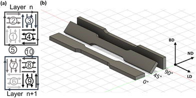 | ||
| Fig. 1 (a) Checkerboard scan strategy and (b) tensile sample build orientation. Arrows denote build direction (BD), loading direction (LD) and normal direction (ND). | ||
Tensile test samples are placed atop the build platform along their long edge in three orientations (0°, 45° and 90°), as presented in Fig. 1(b). One set of each parameter and orientation was produced atop the substrate, with four identical builds produced for validation purposes and two subjected to post-process solution annealing.
Post-process heat treatment conditions
A post-process solution annealing heat treatment was applied to restore the microstructural equilibrium of the laser melted duplex stainless steel. An Abar Ipsen HR-50 vacuum furnace was employed on samples attached to the substrate to minimise warping due to the internal stress of the samples. Conditions were selected to exceed the critical cooling rate of 0.8–0.9 °C s−1 to prevent the formation of the deleterious precipitates.82 The solution annealing temperature of 1150 °C was selected as it resulted in the greatest γ-austenite volume fraction from a range of temperatures on UNS S32750-grade super duplex stainless steel weldments.83 Thus, the samples were heat treated at 1150 °C for 30 min, prior to a high-pressure nitrogen quench with an average cooling rate of 1.72 °C s−1 and, a 5 °C s−1 cooling rate over the first 500 °C.Powder analysis
Powder size and distribution were measured using Malvern Morphologi 4 static automated imaging equipment with >36![[thin space (1/6-em)]](https://www.rsc.org/images/entities/char_2009.gif) 000 particles measured. The volumetric particle size distribution is presented in (Fig. 2(a)), with a scanning electron microscopic (SEM) image in the inset acquired using a JEOL 7800F Prime field emission scanning electron microscope, showing the presence of some satellites after the atomisation process. The crystallographic phases of the atomised powder were determined by X-ray diffraction (XRD) using a Bruker D8 Advance diffractometer with a CuKa radiation source (λ = 0.154 nm), which we operated at 40 kV at an emission current of 40 mA. The XRD scanning speed was set to 0.05° per min across the 2θ range between 20° and 90° and the XRD patterns were indexed using the Match! 3 software. The base powder is predominantly δ-ferritic after atomisation (Fig. 2(b)), with some small γ-austenite peaks on account of the high cooling rate during atomisation restricting the γ-austenite formation.28
000 particles measured. The volumetric particle size distribution is presented in (Fig. 2(a)), with a scanning electron microscopic (SEM) image in the inset acquired using a JEOL 7800F Prime field emission scanning electron microscope, showing the presence of some satellites after the atomisation process. The crystallographic phases of the atomised powder were determined by X-ray diffraction (XRD) using a Bruker D8 Advance diffractometer with a CuKa radiation source (λ = 0.154 nm), which we operated at 40 kV at an emission current of 40 mA. The XRD scanning speed was set to 0.05° per min across the 2θ range between 20° and 90° and the XRD patterns were indexed using the Match! 3 software. The base powder is predominantly δ-ferritic after atomisation (Fig. 2(b)), with some small γ-austenite peaks on account of the high cooling rate during atomisation restricting the γ-austenite formation.28
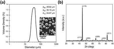 | ||
| Fig. 2 (a) Volumetric powder particle size distribution; inset: SEM image of powders. (b) XRD pattern of the powder. | ||
Mechanical and corrosion testing setup
Tensile tests were conducted using a Tinius Olsen H50KS, following the ASTM standard E8M for rectangular samples at a crosshead speed of 0.2 mm min−1, without the use of an extensometer. A sub-size sample defined with a gage length, width and thickness of 25, 6 and 3 mm respectively was used as the base model. Tensile testing conditions and sample sizes are similarly reported in other PBF-L works for comparable alloys.84–86 Fracture surface characterisation was established from 6 mm tall sections cut off one half of each broken sample. A Hitachi SU-70 SEM was used for higher magnification imagery of the fracture surfaces up to 20![[thin space (1/6-em)]](https://www.rsc.org/images/entities/char_2009.gif) 000× magnification.
000× magnification.
Instrumented indentation technique was used to investigate the variation of micromechanical hardness in samples. An Anton Paar MCT3 system equipped with a Berkovich indenter tip was used at room temperature with 100 indentations taken on each sample in a 10 × 10 matrix at a spacing of 40 μm between indents. A maximum load (Pmax) of 100 mN was applied for each indent with a hold time of 10 s at Pmax. The Oliver–Pharr method was employed to determine the maximum load, contact depth and projected area based off the loading-displacement curves obtained. The following equations were used to calculate HVIT as follows:
 | (1) |
 | (2) |
| A = 24.5hc2 | (3) |
 | (4) |
Cyclic potentiodynamic polarisation (CPP) tests were conducted in a 3.5 wt% NaCl solution to evaluate the corrosion response of the alloys before and after solution annealing in a chloride-containing aqueous environment. A BioLogic potentiostat controlled by the EC lab software was employed. A flat cell with a three-electrode configuration was used. An exposed surface of 1 cm2 of the alloy was used as the working electrode, while a silver–silver chloride reference electrode and a platinum mesh counter electrode were also included in the setup. The samples were mounted in an epoxy resin and the opposite side connected electrically with copper wires. The exposed surface of the sample was prepared by grounding with silicon carbide paper diminishing grit to 2000, followed by ultrasonic cleaning with ethanol. Prior to testing, the samples were conditioned in a 3.5 wt% NaCl electrolyte for 1 h to obtain a relatively stable open circuit potential. Polarisation scans were conducted linearly from 0.25 V below the open circuit potential to 1 VAg/AgCl at a scanning rate of 1 mV s−1 with a limiting current density of 1 mA cm−2. The tests were conducted under the naturally aerated condition at room temperature (25 °C), with each test repeated three times for reproducibility.
Microstructural characterization
After the testing samples were sectioned using a diamond saw from the grip area of each dog-bone sample. These samples were hot mounted in a conductive resin and ground with SiC papers of diminishing grit from 180 to 2400 and, polished on felt pads using diamond pastes from 6 to 1 μm. A final oxide polishing solution (0.04 μm) stage was incorporated for electron back scatter diffraction (EBSD) followed by immersion in ethanol in an ultrasonic bath. The EBSD images were taken using a JEOL 7800F Prime field emission SEM with an Oxford Instruments Symmetry S2 detector. Measurements were taken at accelerating voltage of a 20 kV and a probe current of 35 nA at a step size of 0.2 μm. The AztecCrystal software was used for EBSD image analysis with the MTEX Matlab toolbox software used to determine the relationships between phases and Schmid factor analysis. Microstructural imaging was taken by electro-etching the sample with a 60% HNO3 – 40% H2O solution at an applied voltage of 10 V for 6 seconds, followed by rinsing with ethanol. Imaging was carried out using an Olympus BX51M optical microscope at 200× magnification.We confirmed the presence of crystallographic phases in the bulk by means of XRD using the same Bruker D8 Advance diffractometer and process presented in the Powder analysis section above. The indexing of XRD patterns was carried out using Match! 3 software, and the Rietveld refinement was calculated using the Topas V5 software.
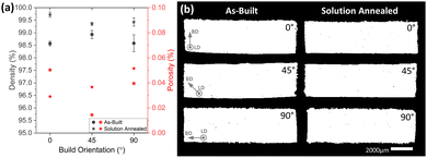
Archimedes density analysis was performed using the samples cut for metallographic evaluation, with measurements taken using a Mettler Toledo XS204 mass balance in air and in ethanol repeating each measurement three times, with results represented in Fig. 3(a). Using a reference density of 7.7 g cm−3, densities for all samples exceeded 98.5%, with improvements in density recorded after solution annealing due to the greater austenite fraction.87 Micrographs taken at the tensile cross-section are binarized and presented in Fig. 3(b), with the corresponding porosity fraction measured using ImageJ, image processing software, which is reported in Fig. 3(a). Negligible porosity is evident in the cross-section with a volume fraction <0.06% for all samples and orientations.
Results and discussion
Microstructure
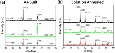
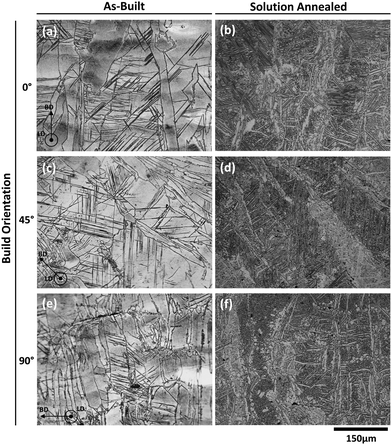
Crystallographic phases present in the as-built and solution-annealed samples were determined via XRD patterns, presented in Fig. 4. The dual phases of δ-ferrite and γ-austenite were observed in both samples, however, with different relative intensities. The as-built samples (Fig. 4(a)) show high intensities for the δ-ferrite phase in comparison to the γ-austenite phase, expected due to the δ-ferritic nature of the powder and fast cooling during PBF-L, restricting the γ-austenite growth.28,76 Unlike other PBF-L works processing the same alloy composition and powder supplier, γ-austenite peaks are observed at a 2θ of 50.2° for all build orientations and, at a 2θ of 73.9° for the 0 and 45° build orientations.28,32,88 These peaks are also observed in the powder XRD (Fig. 2(b)), indicative of retention after the PBF-L process. After solution annealing, the γ-austenite peak intensity greatly increases, evident in Fig. 4(b), with comparable peak profiles across all build orientations. The relative phase fractions of all samples were evaluated by the Rietveld refinement, which are summarised in Table 1, and comparatively evaluated against the EBSD phase maps in this section.The photomicrographs of the as-built and the solution-annealed samples used for the tensile tests are presented in Fig. 5 in order to establish the structure and property relationships, with the arrows inserted denoting the build direction (BD) and micrographs taken out of plane of the tensile direction (TD). The as-built microstructures consisting of long columnar δ-ferrite grains with sporadic γ-austenite precipitation along the grain boundaries (only evident under SEM) and the intersecting black Widmanstätten γ-austenite needles are observed in Fig. 5. These needles are observed in similar works and reported to grow from allotriomorphic γ-austenite, originally forming along grain boundaries,76.89 This growth is reported to follow a diffusional mechanism with the dominant Kurdjumov–Sachs phase relationship, with growth occurring between 700 and 1100 °C subjected to rapid cooling.90,91
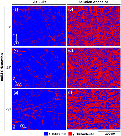
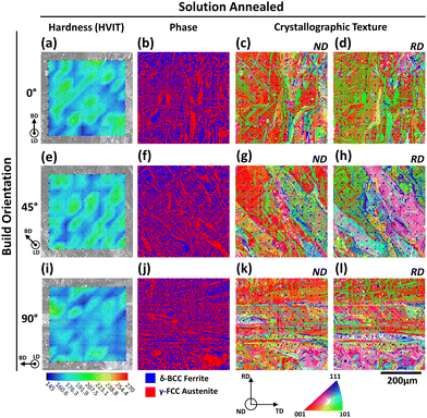
The underlying δ-ferritic grain morphology is retained in the solution-annealed samples similarly noted by Nigon et al. though, compositionally, γ-austenite precipitation is increased with finer Widmanstätten γ-austenite needles and inter-granular precipitates evident in white.92 The retention of this underlying δ-ferritic grain morphology after solution annealing is reported by Balluffi et al. to be due to the preferential nucleation and growth of γ-austenite at δ-ferrite grain boundaries.93 Widmanstätten γ-austenite formation is attributed to the holding temperatures between 700 and 1100 °C, corresponding to the solution annealing cycle employed in this study.90 Phase maps and corresponding phase content fractions in Fig. 6 and Table 1 show comparable austenite fractions for each orientation with only a slight increase in the 45° orientated sample on account of its greater austenite content in the underlying as-built microstructure.
Phase fraction
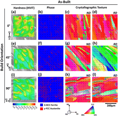
The primarily δ-ferritic microstructure in laser-melted samples produced in the as-build state is clearly evident in the phase maps presented in Fig. 6(a), (c) and (e). Austenite growth can be seen in limited regions along grain boundaries, intragranular and as Widmanstätten needles in all build orientations. The 45° build orientation shows a slightly greater γ-austenite content than that of the other orientations, as noted in Table 1. However, comparative works on PBF-L processing of the same alloy exhibit lower γ-austenite contents (<1%) with growth exclusively allotriomorphic along grain boundaries.32,88,94–97 The Rietveld Refinement of XRD patterns (Fig. 4(a)) validate the greater γ-austenite content in the as-built samples, with the γ-austenite content as great as 9.47% in the 90° orientated sample (Table 1). The greater γ-austenite content observed in this work is due to the pulsed laser and keyhole melt mode in the equipment used herein, which results in a deep melt pool with greater cooling rates, up to 107 K s−1, compared to conductive mode melting, promoting Widmanstätten austenite growth and increasing relative austenite content in the sample.98–100After solution annealing, the γ-austenite content increases significantly, up to 59.46%, with nucleation intergranular, along grain boundaries and as Widmanstätten needles, as shown in Fig. 6(b), (d) and (f). The phase ratios were validated by Rietveld Refinement of XRD patterns (Table 1), with analogous results to EBSD phase maps. As mentioned in the previous section, the underlying δ-ferritic grain morphology after solution annealing is retained after solution annealing, with the preferential nucleation of grain boundary γ-austenite along prior δ-ferrite grain boundaries. Yet overall γ-austenite is homogeneously dispersed in all samples, with a greater preference for Widmanstätten formation in the 0 and 45° orientation, given the slower cooling rate observed in these samples by virtue of their longer melt tract lengths in the build plane, 5 and 4.2 mm respectively and the greater average scanned area for each layer.101 The 90° sample has a short 2.5 mm-long tract in the build plane and a smaller scanning area for each layer, resulting in greater cooling rates and less Widmanstätten γ-austenite formation from prior δ-ferrite grain boundaries.90,102 Further evidence of this is exhibited in the Grain boundary interface orientation relationship section (Fig. 12).
Crystallographic texture
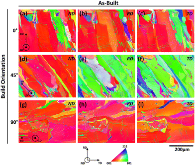
The crystallographic texture has been widely reported to significantly influence the mechanical and corrosion responses of the alloy. The cross-sectional crystallographic texture maps of tensile samples in the as-built state for each orientation under the as-built and solution-annealed conditions, taken along the normal direction (ND), rolling direction (RD) and transverse direction (TD) are presented in Fig. 7. A strong 〈001〉 crystallographic texture of δ-ferrite-BCC is present in the normal direction for all build orientations as reflected in the high multiples of uniform density (MUD) values of 8.42, 7.12, and 6.76 for the 0°, 45° and 90° samples respectively in Fig. 10(a), (d) and (g). The 〈001〉 texture preference is characteristic to cubic ferrous alloys, as it is the fast growth direction following the direction of heat flow.103 The vertical heat flow within the melt pool along its centreline facilitates this 〈001〉 orientation, with alignment of the melt pools contributing to epitaxial growth along the BD.63,70 Although a checkerboard scan strategy was employed in this work, whereby the scan direction rotates by 90° after each layer, Carter et al. reported the presence of long elongated grains with a strong 〈001〉 texture along the build direction.104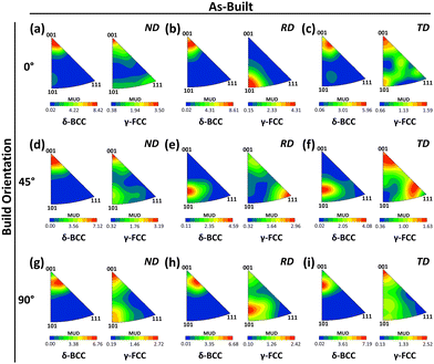 | ||
| Fig. 8 Inverse pole figures of the as-built sample texture maps presented in Fig. 7 in the; (a)–(c) 0°, (d)–(f) 45° and (g)–(i) 90° build orientations. Inverse pole figures are out-of-plane, in the tensile direction (TD). | ||
Evident in the rolling (RD) and the transverse direction (TD) (Fig. 7(b, c), (e, f) and (h, i)) is the change in preferential crystallographic texture with build orientation. For the 0 and 90° orientated samples, the δ-ferrite-BCC grains exhibit a strong 〈001〉 texture; however, the 45° orientated sample reveals a 〈203〉 texture in the {011} plane family as RD and TD maps are taken 45° to the loading direction similarly reported for comparable cubic alloys with the same build direction.105,106
Given the lower grain count and wider statistical variance, γ-austenite-FCC exhibits a lower texture strength under the as-built condition (Fig. 10) with maximum MUD values <4.31, probably due to the lower γ-austenite and wider statistical variance. However, it is interesting to note the relationship between δ-ferrite-BCC and γ-austenite-FCC. Both phases exhibit the same 〈001〉 texture in the ND, a result of the fast growth direction of the phase. However, in the RD, the texture is 45° out of plane with the corresponding δ-ferrite-BCC phase.
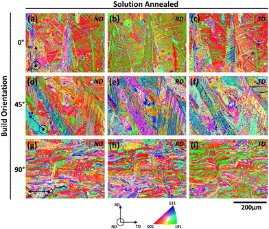
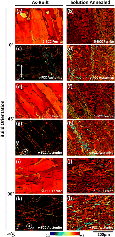
As reported in the prior section, the δ-ferrite grain morphology in the as-built samples is retained after the solution annealing process, evident in the crystallographic texture maps of Fig. 9, showing the underlying grain build directions and in the inverse pole figures of Fig. 10, showing similar crystallographic textures.92,93 The result of this is the same δ-ferrite and γ-austenite texture direction after annealing, however, with a different texture strength. On average, the texture strength decreases after solution annealing for all build orientations and texture directions, as observed in other PBF-L works.31,33 Xiang et al. reports this due to both the recrystallisation and the formation of grains without a preferred orientation and high-solution annealing temperatures driving γ-austenite nucleation and randomness of preferential crystallographic orientation.33 The crystallographic orientation relationship between the δ-ferrite and γ-austenite is important to the texture strength and is studied in detail in the following section.
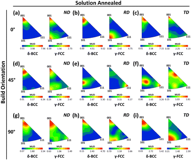 | ||
| Fig. 10 Inverse pole figures of solution-annealed sample texture maps presented in Fig. 9 in the; (a)–(c) 0°, (d)–(f) 45° and (g)–(i) 90° build orientations. Inverse pole figures are out-of-plane, in the tensile direction (TD). | ||
Grain interface orientation relationship
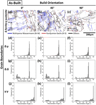
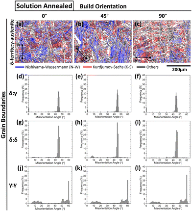
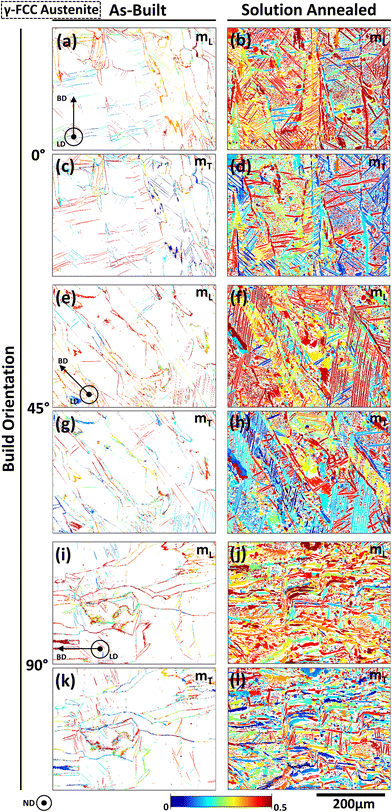
On the whole, δ-ferrite:γ-austenite interfaces under both the as-built and solution-annealed conditions exhibit a misorientation peak of 45–45.6° (Fig. 11(a)–(f) and 12(a)–(f)) fitting the orientation relationships of Kurdjumov–Sachs (K–S), Nishiyama–Wassermann (N–W), Pitsch (P), Greninger–Troiano (G–T) and Bain (B), as presented in Table 2.33,107 Given a tolerance in the orientation relationship of 2° from ideal, the N–W orientation relationship is more prominent in the as-built and solution-annealed samples (Table 3) especially in the 0° and 45°-orientated samples with average length fractions >21% with the remaining orientation relationships categorised as others.107,108 However, when comparing the build orientations, it can be observed that the 0° sample contains comparable length fractions of δ-ferrite:γ-austenite interfaces with the N–W and K–S relationship. This difference in length fractions can be explained by the relative increase in Widmanstätten γ-austenite in the 0° and 45° build direction samples (Fig. 11(a), (b) and 12(a) and (b)), which follow the N–W orientation relationship as compared to the K–S orientation relationship of grain boundary austenite. Although the difference between the N–W and K–S orientation relationship is ≤3.13°, the preferred N–W orientation relationship of Widmanstätten γ-austenite:δ-ferrite is not widely reported, with classic works highlighting the preferential K–S orientation relationship possibly due to difference in unit cell spacings.91,109,110 Considering the interfaces between similar phases before and after solution annealing, δ-ferrite:δ-ferrite interfaces exhibit a misorientation peak at 45–46° (Fig. 11(g)–(i) and 12(g)–(i)) with a misorientation peak at 60° for γ-austenite:γ-austenite interfaces (Fig. 11(j)–(l) and 12(j)–(l)) representing Σ3 (〈111〉) grain boundaries, notably reported in the hot rolled duplex stainless steel alloy with formation in the 〈111〉 direction, as this constitutes the configuration with the minimum energy.107,111,112| Orientation relationship | Parallelism | Minimum angle/axis |
|---|---|---|
| Kurdjumov–Sachs (K–S) | {111}γ//{110}δ | 42.85° 〈0.968 0.178 0.178〉 |
| 〈110〉γ//〈111〉δ | ||
| Nishiyama–Wassermann (N–S) | {111}γ//{110}δ | 45.98° 〈0.976 0.083 0.201〉 |
| 〈112〉γ//〈110〉δ | ||
| Pitsch (P) | {100}γ//{011}δ | 45.98° 〈0.083 0.201 0.976〉 |
| 〈011〉γ//〈111〉δ | ||
| Greninger–Troiano (G–T) | {111}γ//{110}δ | 44.23° 〈0.973 0.189 0.133〉 |
| 〈123〉γ//〈133〉δ | ||
| Bain (B) | {100}γ//{100}δ | 45° 〈1 0 0〉 |
| 〈100〉γ//〈110〉 δ |
| Orientation relationship | As-built | Solution-annealed | ||||
|---|---|---|---|---|---|---|
| 0° | 45° | 90° | 0° | 45° | 90° | |
| Kurdjumov–Sachs (K–S) | 12.4 ± 1.2 | 9.6 ± 2.1 | 13.4 ± 0.9 | 27.6 ± 1.2 | 24.3 ± 0.6 | 31.7 ± 3.5 |
| Nishiyama–Wassermann (N–S) | 21.2 ± 12.4 | 24.6 ± 12.9 | 10.9 ± 2.2 | 28.2 ± 1.1 | 28.9 ± 4.2 | 11.0 ± 4.6 |
Instrumented indentation mapping
Instrumented indentation mapping of samples (Fig. 13 and 14) is used to connect microstructures and local property response. In general, the as-built microstructure is harder than the solution-annealed microstructure, exhibiting a peak hardness of 268.3 HVIT in comparison to 230.2 HVIT after solution annealing. The higher hardness in the as-built samples is reported due to the fine cellular structure, columnar grain growth and residual stress.114,115 The decrease in hardness is widely reported to be the result of recrystallisation after solution annealing with the greater volume of the softer γ-austenite phase.33,76,80,116,117 Thus, troughs in hardness maps for both the as-built and solution-annealed samples occur with the hardness indent within a γ-austenite grain. In contrast, peak hardness measurements in the as-built samples (Fig. 13) are observed at δ-ferrite:δ-ferrite grain boundaries and at Widmanstätten γ-austenite sites, the latter reporting greater hardness values due to greater nitrogen content solid solutions strengthening the phase.118–120In the case of solution-annealed samples (Fig. 14), hardness peaks occur within δ-ferrite grains with a shorter range between the peak and trough values, by virtue of the recrystallisation and stress relieving of the microstructure.33 It may also be noted that there is no distinct correlation between the hardness and the crystallographic texture for the as-built and solution-annealed samples as comparable textures in the normal direction are observed for each build orientation.
Tensile properties
Engineering stress–strain curves in Fig. 15 show the difference in mechanical response of the super duplex alloy under the as-built and solution-annealed conditions. Comparing the two graphs and result summary in Table 4, it is clear that the δ-ferrite-dominated as-built sample has a higher ultimate tensile strength (UTS) (792.2–904.4 MPa) than the solution-annealed samples (677.5–804.5 MPa). The trade-off in ductility is clear with strain at facture values of 30.6–50.1% in the solution-annealed samples reducing to 15.4–29.8% in the as-built samples. Similar observations were made in other duplex stainless steel works processed by PBF-L.30,31,88 The greater UTS in the as-built samples is expected with the BCC δ-ferritic structure given less slip systems compared to γ-austenite, additionally the fine cellular solidification structure, high dislocation concentration, and the grain pinning further attribute to the improved performance.121 Essentially mechanical strength is comparable to the work by He et al. for the same alloy, with an improvement in elongation at fracture under both the as-built and solution-annealed conditions.97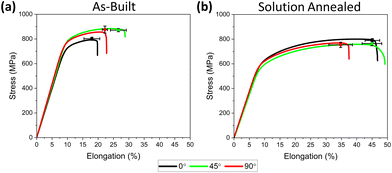 | ||
| Fig. 15 Tensile results for (a) as-built and (b) solution-annealed samples at each build orientation. | ||
| Sample | As-built | Solution-annealed | ||||
|---|---|---|---|---|---|---|
| 0° | 45° | 90° | 0° | 45° | 90° | |
| Yield strength (MPa) | 691.7 ± 27.4 | 725.1 ± 29.4 | 723.5 ± 20.7 | 545.0 ± 22.1 | 510.6 ± 8.2 | 523.3 ± 11.4 |
| Ultimate tensile strength (MPa) | 801.5 ± 12.5 | 871.2 ± 17.9 | 875.9 ± 28.5 | 789.4 ± 15.2 | 764.1 ± 24.6 | 753.8 ± 21.6 |
| Elongation at fracture (%) | 18.0 ± 2.6 | 26.6 ± 3.2 | 22.2 ± 0.8 | 45.1 ± 2.4 | 44.9 ± 5.2 | 34.4 ± 3.8 |
The as-built samples orientated at 45° and 90° (Fig. 15(a)) exhibit favourable properties with the high UTS (871.2 and 875.9 MPa) values and the greatest strain to fracture (26.6 and 22.2%). Given the comparable phase ratios across all build orientations (Fig. 6), this increase in strength is probably the result of lower residual stress and the number of built layers for each orientation. The chessboard scan strategy is reported to have higher residual stresses than a 90° rotating scan vector, and these stresses are tensile on the upper surface and can be close to the yield stress of the material.122–124 The residual stresses are at their highest with the 0°-orientated sample as it has the longest laser irradiation time per layer and greater exposed surface area. Elongation at fracture is greatest in the samples orientated 45° to the build platform, and similar observations were reported in cubic alloys processed by PBF-L. As tensile testing is orientated at an angle to the melt pool tract–tract and layer–layer boundaries, the failure projection path is reported to improve ductility in the 45° sample.105,125 As opposed to PBF-L reported in the literature whereby the 90° orientated samples are built vertically along the build direction, resulting in preferential fracture pathways as there is limited resistance to dislocation motion of the grains and alignment of melt pool boundaries perpendicular to the testing direction, which act as locations of weakness due to poor interfacial bonding of the consolidated layers, the 90° samples considered herein are rotated along their length, contributing to improved strength and ductility.58,125
The ratio of δ-ferrite to γ-austenite is a greater influence on tensile properties in solution-annealed samples, with 72.4 MPa spread in UTS values across the build orientations. However, the 90° sample presents poorer elongation properties, which are probably the result of austenite formation type, given that the 90° sample contains less of the stronger Widmanstätten austenite.119 This is a result of the faster cooling rate during laser melting and less Widmanstätten austenite in the as-built structure.
The influence of the crystallographic texture on mechanical properties can be evaluated by Schmid's law as follows:
| τRSS = σm | (5) |
| τCRSS = σymmax | (6) |
The Schmid factors for each sample in the direction of loading (ND) were calculated from the EBSD data, and are presented in Fig. 16 and Table 6. A Schmid factor between 0.40 and 0.49 in δ-ferrite is evident in the as-built samples, indicative of an ease in grain slip of this phase.127 The 0° build orientation exhibits the lowest Schmid factor across each of the slip planes (Fig. 16(a)). This can be explained by the stronger 〈001〉 crystallographic texture (Fig. 8(a)) in this orientation. For the primary BCC slip system, {110} 〈111〉, the maximum Schmid factor (mmax) for the BCC (δ-ferrite) unit cell is 0.408 (Table 5) in the 〈001〉 direction, identical to that of the 0° build orientation and as such exhibits a single crystalline-like texture. The larger Schmid Factor in the 45° and 90° build orientations can be attributed to the considerable volume of aberrant grains in the samples.59 The difference in Yield strength between build orientations is 0.2–4.6%, similar to the difference between equivalent Schmid factors (0.9–5.3%) across all slip systems. This suggests that the difference in yield strength is influenced by crystallographic texture. However, the 0° build orientation sample with its lower Schmid factor exhibits the lowest yield strength of all build orientations, probably induced by the high residual tensile stress of the chessboard scan strategy, close to the yield stress of the material.122–124 Additionally, both the BCC δ-ferrite and FCC structured γ-austenite exhibit high Schmid factors (Table 6) in comparison to maximum values reported (Table 5), indicative of a less ordered crystallographic texture. Similar observations were made in FCC γ-austenitic alloys processed by PBF-L, containing equivalent Schmid factors with analogous texture strengths.126,128,129 These factors suggest a low likelihood of crystallographic texture strengthening by both the BCC δ-ferrite and FCC γ-austenite phases.
After solution annealing, the BCC δ-ferrite Schmid factor increased along the {110} 〈111〉 slip system for all build orientations indicative of recrystallisation weakening the 〈001〉 preferred orientation (Fig. 16(b), (f) and (j)).33 Recrystallisation also lead to narrowing of the difference in Schmid factors between build orientations (0.9–1.9%) for the BCC and FCC slip systems. The equivalent Yield strength difference is between 2.4 and 6.3%, suggesting a lower probability of crystallographic texture strengthening.
Differences in ductility can be attributed to the formation of deformation twinning, delaying necking and improving ductility.41,128 The formation of twins is greatly influenced by the crystallographic texture and can provide insights into the tensile response of different build orientations.59,128
In duplex stainless steels, it is reported that FCC structured γ-austenite strengthens duplex stainless steels from dislocation formation and twin hardening.130 Meanwhile, the BCC δ-ferrite deforms easier by the slip of dislocations due to the considerably higher stacking fault energy.131,132 As such, ductility is directly related to the γ-austenite volume content and its crystallographic texture. The stress level required to initiate twinning in an alloy is known as the critical stress for deformation twinning (σTW) and can be calculated for the γ-austenite phase from Byun's formula as follows:133
 | (7) |
 | (8) |
 | (9) |
| Sample | As-built | Solution-annealed | ||||
|---|---|---|---|---|---|---|
| 0° | 45° | 90° | 0° | 45° | 90° | |
| True stress at yield (MPa) | 878.2 ± 28.8 | 918.9 ± 27.2 | 932.2 ± 32.2 | 726.2 ± 14.0 | 684.8 ± 16.8 | 703.6 ± 16.5 |
| Critical stress for deformation twinning (MPa) | 450.8 ± 3.3 | 421.8 ± 3.3 | 422.1 ± 3.7 | 433.4 ± 1.9 | 437.2 ± 2.3 | 444.3 ± 2.1 |
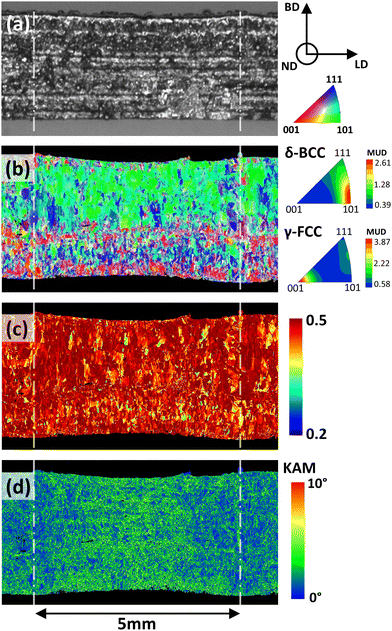
Evident after tensile testing as-built samples in the 45° build orientation is periodic necking (Fig. 18), with a 5 mm peak-to-peak distance, consistent with the checker length in the checkerboard scan strategy. The cause of this “wavy” necking is probably due to the greater remelting present at the boundary of each checker, seen in prior work to greater recrystallisation and enlarged grains.76 A cross-sectional crystallographic texture map in the normal direction is presented in Fig. 18(b) with a visible difference in grain size from the bottom to the top, and the small grains at the bottom result from the melting of the unsupported powder layer, enlarging with increasing solid layers. Altogether, a weak 〈101〉 crystallographic texture is observed for the δ-ferrite grains (MUD < 2.61) and complementary 〈001〉 γ-austenite grain orientation (MUD < 3.87), resulting from EBSD imaging at 45° to the build orientation. Similar crystallographic textures were observed in highly deformed wrought duplex stainless steels, with strain-induced 〈101〉 texture development.143 The contribution of this texture on mechanical properties can be evaluated from Schmid factor analysis. The Schmid factor map in Fig. 18(c) provides insights into the contribution of crystallographic texture on mechanical properties. Schmid factors of 0.44, 0.47 and 0.48 are calculated for the {110} 〈111〉, {112} 〈111〉 and {123} 〈111〉 (δ-ferrite) slip systems, indicative of an ease in slip. It may be noted that Schmid factor (0.47) in the 〈011〉 direction of the {112} 〈111〉 slip system is identical to the maximum Schmid factor (mmax) presented in Table 5, suggesting single crystalline-like texture. This texture is probably induced by the tensile deformation, where twinning of the γ-austenite leads to hardening of the {112} 〈111〉 slip system in δ-ferrite.144 However, a less ordered crystallographic texture of the γ-austenite can be deduced from the high Schmid factor of 0.44. The Kernel average misorientation (KAM) map presented in Fig. 18(d) represents the distribution of dislocations in the necked region, with a decrease in dislocations from the centre of the necked region to the remelted-recrystallised contour region of the checker. Recrystallization by laser remelting is reported in other PBF-L works to result in increased elongation and strength, by increasing the bonding between melt pools and through hetero-deformation-induced strengthening between the recrystallised and non-recrystallised structures.145,146 This periodic necking is not as predominant in the 0°-orientated sample probably due to the thinner gage section in the build direction, though it was lightly evident in the 90°-orientated samples, corroborating the mechanical property response reported above.
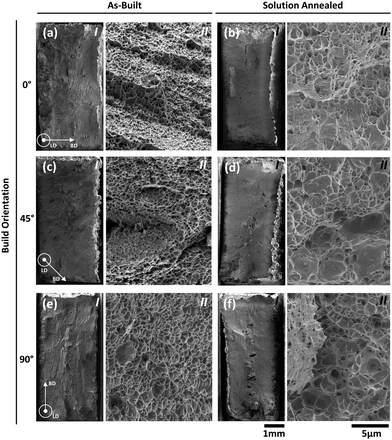
The fractured surfaces of both the as-built and solution-annealed samples are presented in Fig. 19. The as-built samples show lesser necking and ductility than those of the solution-annealed samples and show evidence of cleavage fractures consistent with the brittle fracture modes induced by the dominant BCC δ-ferrite microstructure. The areas of ductility are evident in the as-built samples at 0° and 90° along the upper face, as shown in Fig. 19(a) and (e) as regions of necking and at the centre of the 0° sample as a cone-shaped fracture. Necking is less visible in the 45° sample, however, as fracture occurred at the inter-checker boundary. Comparably, solution-annealed samples show a ductile trans-granular fracture with sufficient necking along the gage width, as evident in Fig. 19(b), (d) and (f). The solution annealing treatment results in a change in the microstructure and possible recrystallisation of the austenite phase growing within the ferrite matrix. This is expected to enhance the ductile nature of the specimens, which is clearly evident looking at the necking and other features of the photographs presented in Fig. 19(b), (d), and (f). It may also be observed that cracks are initiated and evidently dispersed in the central regions of the fractured surfaces, but there was insufficient energy to allow them to grow and propagate the fracture across the surface.
Higher magnification images of the fracture surfaces highlight the micro-sized dimple fracture features, reported by Sufiiarov et al. to constitute ductile transgranular fractures and suggested as comparable in size to solidification cells, suggesting cell size of the order of 0.3–1.2 μm comparable to other PBF-L-processed duplex alloys.77,96,147,148 Enlarging of these dimples is evident after solution annealing with sizes between 0.8 and 4.5 μm, notable in laser-melted alloys after heat treatment processing formed as a result of the recrystallisation process and equilibrium microstructure formation.149 Dimple morphologies also vary between build orientations, with the as-built sample at 45° showing evidence of smaller and more equiaxed dimples than the larger and more elongated dimples in 0° and the 90° samples. As Janssen et al. reports, uniaxial loading results in equiaxed dimple morphology, whereby tensile tearing produces more elongated dimples.150 It may be noted that the fracture directions are different in different samples, as already noted. Further, the direction of the growth of the cellular structures is also different from one build orientation to the other. It is understood that the variations in the dimple sizes from one build orientation to the other, as noted in Fig. 19, are the results of the combined effects of these two aspects: the direction of growth of the cells and the direction of fracture and the consequent direction at which the fractured cells are observed.
Corrosion response
The corrosion responses of the samples produced under the as-built and solution-annealed conditions were studied by cyclic potentiodynamic polarisation (CPP), as presented in Fig. 20. Comparing the microstructures of samples under the as-built and solution-annealed conditions, the results show an overarching improvement in corrosion resistance after solution annealing, with a pitting potential (EPit) of solution-annealed samples of, on average, 29 mV higher than that in the as-built state, signifying increased pitting resistance. The passive region of the cyclic potentiodynamic polarization (CPP) curves for solution-annealed samples illustrates fewer fluctuations and spike-like features. This suggests a reduced formation of metastable pitting in the alloy. Furthermore, the lower passive current density indicates a slower dissolution rate of annealed samples than that of the as-built samples. This can be predominantly attributed to the increased γ-austenite content in the solution-annealed samples. The increased austenite content, as both Widmanstätten needles and inter-granular precipitates, decreases the corrosion rate of the alloy as the greater Ni and N contents in the austenitic phase increase passivation ability and reduce the oxidation rate.78,151 The removal of residual stress is also reported to improve the corrosion resistance of PBF-L-processed alloys.89,152,153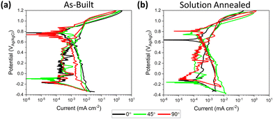 | ||
| Fig. 20 Cyclic potentiodynamic polarisation curves for (a) as-built and (b) solution-annealed samples at each build orientation in 3.5 wt% NaCl. | ||
A similar CPP response is observed for all the as-built samples, as shown in Fig. 20(a). Only a slight variation in CPP response is observed for the three orientations, with the 45° and 90° orientations showing relatively high pitting potentials (EPit), 11 mV and 18 mV respectively, compared to that built with a 0° build orientation. The lower volume of Widmanstätten γ-austenite in the 90° sample (Table 3) results in improved corrosion properties, given the structure depletion in corrosion-resistant elements and the formation of secondary γ-austenite.154–156 Thus, concluding that the ratio of γ-austenite to δ-ferrite is more influential to corrosion response than the crystallographic texture, given comparable phase ratios across the build orientations. Similar observations were made by Nigon et al. for the standard duplex stainless steel processed by PBF-L.34 In general, the pitting potential values of the as-built samples are comparable to the work by Akilan et al. for the same alloy with similar part densities.94
In contrast, the solution-annealed samples reveal a different trend, as illustrated in Fig. 20(b). Specifically, the sample orientated at 0° exhibits a slightly compromised passive corrosion behaviour, evident in its one order of magnitude higher passive current density and less steep slope of the CPP curve compared to other heat-treated alloys. This is probably the product of the 〈011〉 γ-austenite texture (Fig. 10(a)) retained from the as-built microstructure, which is reported by Trisnanto et al. to result in lower corrosion resistance due to its lower atom packing density and greater surface energy than the other orientations,61,157 leading to higher corrosion susceptibility among the solution-annealed samples. The 45° and 90° built direction samples demonstrate the highest pitting potential, 27 mV higher than that of the 0° sample. This can be attributed to the strong texture of δ-ferrite in this sample, given the comparable phase ratios for all orientations.
The comparable Ecorr and Icorr values between the solution-annealed and as-built samples suggest a similar corrosion behaviour during the active dissolution stage prior to the passivation, which is likely influenced by chemical phase variations within the alloys.34,158 However, in the context of corrosion of DSS, evaluating the pitting potential is paramount, as it indicates the material's resistance to localised corrosion. Yet despite their δ-ferrite-dominated microstructure, the as-built samples exhibited promising pitting corrosion resistance because of their solute-rich ferritic structure containing Cr, Ni and Mo alloying elements beneficial to corrosion resistance.159
In addition to the phase content and crystallographic texture, other microstructural features may influence the corrosion resistance of PBF-L-processed alloys, and one such feature is porosity. It is widely reported that increasing the porosity leads to increased pitting characteristics including pit initiation and pit re-passivation behaviour.46,160–164 It is reported that porosity is particularly detrimental above 1%, likely increasing the susceptibility to environmentally assisted cracking.46,160–164 While difficult to completely assess each microstructural feature's influence on corrosion in isolation, porosity is minimal ranging from 0.01 to 0.05%. Furthermore, annealed samples with a slightly higher porosity (45° and 90° build orientation) exhibit lower pitting susceptibility, indicated by lower pitting potential (EPit) values. Thus, porosity plays a less dominant role in the corrosion resistance of PBF-L-processed duplex stainless steel.
Conclusions
In this work, the mechanical and corrosion responses of PBF-L-processed super duplex stainless steels built in three build orientations have been examined and related to their underlying microstructures under both the as-built and heat-treatment conditions. From these findings, the structure–property relationships can be ascertained and the following conclusions are drawn.The as-built microstructures are predominantly δ-ferritic (>90.53%), on account of the δ-ferritic powder material and rapid cooling of the PBF-L process, limiting the γ-austenite growth. Analogously, the γ-austenite ratios (∼7.97%) are discernible for each build orientation. However, a greater volume of Widmanstätten γ-austenite needles is visible in 0 and 45° orientations, given the slower cooling rates from longer melt tract lengths. The shorter scanning area of the 90° orientation exhibits a greater tendency for grain boundary γ-austenite growth. A strong 〈001〉 crystallographic texture is observed in the normal direction of δ-ferrite for all orientations, representing the fast growth direction following the direction of heat flow. Along the rolling direction, the 45° orientation exhibits a rotation in texture equal to the build orientation, exhibiting a {011} plane texture for δ-ferrite.
Solution annealing yields a considerable increase in the γ-austenite ratio (>53.28%) with nucleation along prior grain boundaries and as Widmanstätten needles, in addition to intergranular growth. Thus, the underlying δ-ferritic grain morphology is retained after the annealing process, retaining the as-built crystallographic texture however, at a lower strength resulting from recrystallisation and new grain growth without preferential orientation.
Interfaces between δ-ferrite and γ-austenite grains exhibit a misorientation peak at 45–45.6° and follow the Kurdjumov–Sachs and Nishiyama–Wassermann orientation relationship for grain boundary and Widmanstätten γ-austenite respectively. An equivalent misorientation peak (45–46°) was observed for δ-ferrite:δ-ferrite interfaces in addition to a misorientation peak of 60° for γ-austenite:γ-austenite interfaces, indicative of Σ3 grain boundaries.
The as-built δ-ferritic microstructure is harder due to the fine cellular structure, columnar grain growth and high residual stress, with hardness peaks occurring at δ-ferrite:δ-ferrite grain boundaries and solid solution-strengthened Widmanstätten γ-austenite. Local hardness peaks are observed in the δ-ferrite phase of solution-annealed samples; however, the average hardness decreases after recrystallisation.
The as-built samples exhibit a higher ultimate tensile strength up to 904.4 MPa owing to the BCC δ-ferrite structure with less slip systems and fine cellular solidification structures, though with a trade-off in elongation (<29.8%). Solution annealing restored elongation up to 50.1% by stress relieving and increased ductile FCC γ-austenite content but reduced the tensile strength to <804.5 MPa. Promising tensile strength and elongation are observed in the as-built 45° orientation by virtue of lower residual stress and periodic recrystallisation between scanning checkers. Microstructure equilibrium after solution annealing generated comparable tensile strengths for each build orientation, but with the 90° orientation, exhibiting decreased elongation owing to a lower Widmanstätten γ-austenite content.
The mixed-mode fracture is apparent in the as-built samples with brittle and ductile trans-granular fracture features, with ductile fracture dominant after solution annealing. Micro-dimple-fractured surfaces are observed in both the as-built and the solution-annealed states, enlarging from 0.3 to 1.2 μm in the as-built state to 0.8–4.5 μm after heat treatment from stress relieving and increased γ-austenite content.
Solution annealing fractionally improved pitting corrosion resistance, a result of the increased γ-austenite content as both Widmanstätten needles and inter-granular precipitates and, through the removal of residual stress. The 90° build orientation exhibited slightly higher pitting corrosion resistance in the as-built condition, probably due to the greater chemically homogeneous grain boundary γ-austenite content.
Data availability
The data supporting this article have been included as part of the ESI.†Author contributions
Karl Peter Davidson: conceptualisation, data curation, investigation, formal analysis, writing original draft, review and editing. Ruiliang Liu: data curation, writing review and editing. Chenyang Zhu: data curation, formal analysis. Mehmet Cagiciri: data curation, formal analysis. Li Ping Tan: data curation, formal analysis. Alpravinosh Alagesan: data curation. Sarat Singamneni: supervision, funding acquisition.Conflicts of interest
There are no conflicts to declare.Acknowledgements
Darryll Lee Yee Kai: sample preparation and corrosion analysis. Jiaojiao Wang: X-Ray diffraction data collection. Feng Ji: EBSD analysis direction. Shubo Gao: EBSD analysis direction. Tan Phuc Le: manuscript layout and direction. The authors acknowledge the Facilities for Analysis, Characterization, Testing and Simulations (FACTS) at NTU for access to electron microscopy equipment.References
- S. M. Zahurul Islam and B. Young, Use of stainless steel as structural members in bridge construction and fiber reinforced polymer strengthening, in Joint Conference on Advances in Bridge Engineering-III, ed. D. Bangladesh, A. Okui and B. Ueda, IABSE-JSCE, 2015, pp. 164–173 Search PubMed.
- E. Halling, Stainless steels within desalination for reliable water supply, Int. J. Nucl. Desalin., 2010, 4(2), 142–148 CrossRef CAS.
- K. C. Bendall, Duplex stainless steel in the pulp and paper industry, Anti-Corros Methods and Mater, 1997, 44(3), 170–174, DOI:10.1108/0003559971016712410.1108/0003559971016711510.1108/eb016326.
- G. Chai, U. Kikisäkk, J. Tokaruk and J. Eidhagen, Hyper duplex stainless steel for deep subsea applications, Stainl Steel World, 2009, 27–33 Search PubMed.
- M. Martins and L. C. Casteletti, Heat treatment temperature influence on ASTM A890 GR 6A super duplex stainless steel microstructure, Mater. Charact., 2005, 55(3), 225–233, DOI:10.1016/j.matchar.2005.05.008.
- S. Topolska and J. Labanowski, Impact-toughness investigations of duplex stainless steels, Mater. Tehnol., 2015, 49(4), 481–486, DOI:10.17222/mit.2014.133.
- K. P. Davidson, G. Littlefair and S. Singamneni, On the machinability of selective laser melted duplex stainless steels, Mater. Manuf. Processes, 2021, 37(2), 1446–1462, DOI:10.1080/10426914.2021.2001513.
- K. P. Davidson and S. Singamneni, The mechanics of machining selective laser melted super duplex stainless steels, J. Mater. Res. Technol., 2022, 17, 601–611, DOI:10.1016/j.jmrt.2022.01.025.
- Z. Schulz, P. Whitcraft and D. Wachowiak, Availability and Economics of Using Duplex Stainless Steels, in Corrosion, 2014, All Days, NACE-2014-4345.
- R. Francis and G. Byrne, Duplex Stainless Steels—Alloys for the 21st Century, Metals, 2021, 11(5), 836, DOI:10.3390/met11050836.
- F. Martín, C. García and Y. Blanco, Effect of chemical composition and sintering conditions on the mechanical properties of sintered duplex stainless steels, Mater. Sci. Eng. A, 2011, 528(29–30), 8500–8511, DOI:10.1016/j.msea.2011.08.013.
- L. A. Dobrzański, Z. Brytan, M. Actis Grande and M. Rosso, Properties of duplex stainless steels made by powder metallurgy, Arch. Mater. Sci. Eng., 2007, 28(4), 217–223 Search PubMed.
- P. Salvetr, A. Školáková, D. Melzer, M. Brázda, J. Duchoň, J. Drahokoupil, P. Svora, Š. Msallamová and P. Novák, Characterization of super duplex stainless steel SAF2507 deposited by directed energy deposition, Mater. Sci. Eng. A, 2022, 857, 144084, DOI:10.1016/j.msea.2022.144084.
- M. Koukolíková, P. Podaný, S. Rzepa, M. Brázda and A. Kocijan, Additive manufacturing multi-material components of SAF 2507 duplex steel and 15-5 PH martensitic stainless steel, J. Manuf. Process., 2023, 102, 330–339, DOI:10.1016/j.jmapro.2023.07.057.
- J. Ning, J.-H. Wen, L.-J. Zhang and S.-J. Na, Assessment of the universality of duplex stainless steel powder in laser additive repair based on Schaeffler diagram, Addit. Manuf., 2022, 55, 102864, DOI:10.1016/j.addma.2022.102864.
- J.-H. Wen, L.-J. Zhang, J. Ning, F. Xue, X.-W. Lei, J.-X. Zhang and S.-J. Na, Laser additively manufactured intensive dual-phase steels and their microstructures, properties and corrosion resistance, Mater. Des., 2020, 192, 108710, DOI:10.1016/j.matdes.2020.108710.
- D. Jiang, X. Gao, Y. Zhu, C. Hutchinson and A. Huang, In situ duplex structure formation and high tensile strength of super duplex stainless steel produced by directed laser deposition, Mater. Sci. Eng., A, 2022, 833, 142557, DOI:10.1016/j.msea.2021.142557.
- A. D. Iams, J. S. Keist and T. A. Palmer, Formation of Austenite in Additively Manufactured and Post-Processed Duplex Stainless Steel Alloys, Metall. Mater. Trans. A, 2019, 51(2), 982–999, DOI:10.1007/s11661-019-05562-w.
- Y. Zhang, S. Wu and F. Cheng, A specially-designed super duplex stainless steel with balanced ferrite:austenite ratio fabricated via flux-cored wire arc additive manufacturing: Microstructure evolution, mechanical properties and corrosion resistance, Mater. Sci. Eng., A, 2022, 854, 143809, DOI:10.1016/j.msea.2022.143809.
- S. Pantelakis, M. Eriksson, M. Lervåg, C. Sørensen, A. Robertstad, B. M. Brønstad, B. Nyhus, R. Aune, X. Ren, O. M. Akselsen and S. Koubias, Additive manufacture of superduplex stainless steel using WAAM, MATEC Web of Conf., 2018, 188 DOI:10.1051/matecconf/201818803014.
- V. A. Hosseini, M. Högström, K. Hurtig, M. A. Valiente Bermejo, L.-E. Stridh and L. Karlsson, Wire-arc additive manufacturing of a duplex stainless steel: thermal cycle analysis and microstructure characterization, Weld. World, 2019, 63(4), 975–987, DOI:10.1007/s40194-019-00735-y.
- A. Baghdadchi, V. A. Hosseini, M. A. Valiente Bermejo, B. Axelsson, E. Harati, M. Högström and L. Karlsson, Wire laser metal deposition of 22% Cr duplex stainless steel: as-deposited and heat-treated microstructure and mechanical properties, J. Mater. Sci., 2022, 57(21), 9556–9575, DOI:10.1007/s10853-022-06878-6.
- M. A. Valiente Bermejo, K. Thalavai Pandian, B. Axelsson, E. Harati, A. Kisielewicz and L. Karlsson, Microstructure of laser metal deposited duplex stainless steel: Influence of shielding gas and heat treatment, Weld. World, 2020, 65(3), 525–541, DOI:10.1007/s40194-020-01036-5.
- E. Cederberg, V. A. Hosseini, C. Kumara and L. Karlsson, Physical simulation of additively manufactured super duplex stainless steels – microstructure and properties, Addit. Manuf., 2020, 34, 101269, DOI:10.1016/j.addma.2020.101269.
- S. Roos, F. Barbera Flichi, L. Ortiz-Membrado, C. A. Botero Vega, E. Jiménez-Piqué and L.-E. Rännar, Assessing the viability of high-frequency spot melting for super duplex stainless steel 2507 via electron beam powder bed fusion, J. Mater. Res. Technol., 2023, 27, 5720–5728, DOI:10.1016/j.jmrt.2023.11.028.
- S. Roos, C. Botero and L.-E. Rännar, Electron beam powder bed fusion processing of 2507 super duplex stainless steel. as-built phase composition and microstructural properties, J. Mater. Res. Technol., 2023, 24, 6473–6483, DOI:10.1016/j.jmrt.2023.04.230.
- K. Davidson and S. Singamneni, Selective Laser Melting of Duplex Stainless Steel Powders: An Investigation, Mater. Manuf. Processes, 2015, 31(12), 1543–1555, DOI:10.1080/10426914.2015.1090605.
- K. Saeidi, L. Kevetkova, F. Lofaj and Z. Shen, Novel ferritic stainless steel formed by laser melting from duplex stainless steel powder with advanced mechanical properties and high ductility, Mater. Sci. Eng., A, 2016, 665, 59–65, DOI:10.1016/j.msea.2016.04.027.
- K. P. Davidson and S. Singamneni, Magnetic Characterization of Selective Laser-Melted Saf 2507 Duplex Stainless Steel, JOM, 2016, 69(3), 569–574, DOI:10.1007/s11837-016-2193-6.
- F. Hengsbach, P. Koppa, K. Duschik, M. J. Holzweissig, M. Burns, J. Nellesen, W. Tillmann, T. Tröster, K.-P. Hoyer and M. Schaper, Duplex stainless steel fabricated by selective laser melting – Microstructural and mechanical properties, Mater. Des., 2017, 133, 136–142, DOI:10.1016/j.matdes.2017.07.046.
- S. Papula, M. Song, A. Pateras, X. B. Chen, M. Brandt, M. Easton, Y. Yagodzinskyy, I. Virkkunen and H. Hanninen, Selective Laser Melting of Duplex Stainless Steel 2205: Effect of Post-Processing Heat Treatment on Microstructure, Mechanical Properties, and Corrosion Resistance, Materials, 2019, 12(15), 2468, DOI:10.3390/ma12152468.
- L. Becker, J. Boes, J. Lentz, C. Cui, M. Steinbacher, Y. Li, R. Fechte-Heinen, W. Theisen and S. Weber, Influence of annealing time on the microstructure and properties of additively manufactured X2CrNiMoN25–7–4 duplex stainless steel: Experiment and simulation, Mater., 2023, 28, 101720, DOI:10.1016/j.mtla.2023.101720.
- H. Xiang, W. Zhao and Y. Lu, Effect of solution temperature on microstructure and mechanical properties of selective laser melted Fe–22Cr–5Ni-0.26N duplex stainless steel, J. Mater. Res. Technol., 2022, 19, 1379–1389, DOI:10.1016/j.jmrt.2022.05.124.
- G. N. Nigon, O. B. Isgor and S. Pasebani, Effect of Build Orientation and Annealing on Corrosion Resistance of Additively Manufactured Duplex Stainless Steel in 3.5% NaCl, J. Electrochem. Soc., 2020, 167(14), 141508, DOI:10.1149/1945-7111/abc5dd.
- D. D. Gu, W. Meiners, K. Wissenbach and R. Poprawe, Laser additive manufacturing of metallic components: materials, processes and mechanisms, Int. Mater. Rev., 2013, 57(3), 133–164, DOI:10.1179/1743280411y.0000000014.
- L. E. Murr, S. M. Gaytan, D. A. Ramirez, E. Martinez, J. Hernandez, K. N. Amato, P. W. Shindo, F. R. Medina and R. B. Wicker, Metal Fabrication by Additive Manufacturing Using Laser and Electron Beam Melting Technologies, J. Mater. Sci. Technol., 2012, 28(1), 1–14, DOI:10.1016/s1005-0302(12)60016-4.
- Q. Jia and D. Gu, Selective laser melting additive manufacturing of TiC/Inconel 718 bulk-form nanocomposites: Densification, microstructure, and performance, J. Mater. Res., 2014, 29(17), 1960–1969, DOI:10.1557/jmr.2014.130.
- T. Boegelein, S. N. Dryepondt, A. Pandey, K. Dawson and G. J. Tatlock, Mechanical response and deformation mechanisms of ferritic oxide dispersion strengthened steel structures produced by selective laser melting, Acta Mater., 2015, 87, 201–215, DOI:10.1016/j.actamat.2014.12.047.
- J. P. Kruth, E. Yasa and J. Deckers, Experimental investigation of laser surface re-melting for the improvement of selective laser melting process, in 19th Solid Freeform Fabrication Symposium, Austin, TX, 2008, pp. 321–332.
- K. Saeidi, X. Gao, F. Lofaj, L. Kvetková and Z. J. Shen, Transformation of austenite to duplex austenite-ferrite assembly in annealed stainless steel 316L consolidated by laser melting, J. Alloys Compd., 2015, 633, 463–469, DOI:10.1016/j.jallcom.2015.01.249.
- L. Liu, Q. Ding, Y. Zhong, J. Zou, J. Wu, Y.-L. Chiu, J. Li, Z. Zhang, Q. Yu and Z. Shen, Dislocation network in additive manufactured steel breaks strength–ductility trade-off, Mater.Today, 2018, 21(4), 354–361, DOI:10.1016/j.mattod.2017.11.004.
- W. Xu, M. Brandt, S. Sun, J. Elambasseril, Q. Liu, K. Latham, K. Xia and M. Qian, Additive manufacturing of strong and ductile Ti-6Al-4V by selective laser melting via in situ martensite decomposition, Acta Mater., 2015, 85, 74–84, DOI:10.1016/j.actamat.2014.11.028.
- K. G. Prashanth, S. Scudino and J. Eckert, Defining the tensile properties of Al-12Si parts produced by selective laser melting, Acta Mater., 2017, 126, 25–35, DOI:10.1016/j.actamat.2016.12.044.
- A. Takaichi, Suyalatu, T. Nakamoto, N. Joko, N. Nomura, Y. Tsutsumi, S. Migata, H. Doi, S. Kurosu, A. Chiba, N. Wakabayashi, Y. Igarashi and T. Hanawa, Microstructures & mechanical propertiies of Co-29Cr-6Mo alloy fabricated by selective laser melting for dental applications, J. Mech. Behav. Biomed. Mater., 2013, 21, 67–76 CrossRef CAS PubMed.
- L. Rickenbacher, T. Etter, S. Hövel and K. Wegener, High temperature material properties of IN738LC processed by selective laser melting (SLM) technology, Rapid Prototyping J., 2013, 19(4), 282–290, DOI:10.1108/13552541311323281.
- Q. Chao, V. Cruz, S. Thomas, N. Birbilis, P. Collins, A. Taylor, P. D. Hodgson and D. Fabijanic, On the enhanced corrosion resistance of a selective laser melted austenitic stainless steel, Scr. Mater., 2017, 141, 94–98, DOI:10.1016/j.scriptamat.2017.07.037.
- Y. Zhao, H. Xiong, X. Li, W. Qi, J. Wang, Y. Hua, T. Zhang and F. Wang, Improved corrosion performance of selective laser melted stainless steel 316L in the deep-sea environment, Corros. Commun., 2021, 2, 55–62, DOI:10.1016/j.corcom.2021.09.002.
- X.-q Ni, D.-c Kong, Y. Wen, L. Zhang, W.-h Wu, B.-b He, L. Lu and D.-X. Zhu, Anisotropy in mechanical properties and corrosion resistance of 316L stainless steel fabricated by selective laser melting, Int. J. Miner., Metall. Mater., 2019, 26(3), 319–328, DOI:10.1007/s12613-019-1740-x.
- C. Man, C. Dong, T. Liu, D. Kong, D. Wang and X. Li, The enhancement of microstructure on the passive and pitting behaviors of selective laser melting 316L SS in simulated body fluid, Appl. Surf. Sci., 2019, 467–468, 193–205, DOI:10.1016/j.apsusc.2018.10.150.
- C. J. Todaro, M. Rashidi, R. L. Liu, S. Gao, T. P. Le, J. E. Fronda, J. Setyadji, Y. T. Tang and M. Seita, Laser powder bed fusion of high-strength and corrosion-resistant Inconel alloy 725, Mater. Charact., 2022, 194, 112454, DOI:10.1016/j.matchar.2022.112454.
- F. Kochta, A. Gebert, U. Kühn, S. Oswald, T. Gemming, C. Leyens and J. K. Hufenbach, Improved corrosion behavior of a novel Fe85Cr4Mo8V2C1 tool steel processed by laser powder bed fusion, J. Alloys Compd., 2021, 867, 158887, DOI:10.1016/j.jallcom.2021.158887.
- P. Liu, J.-Y. Hu, H.-X. Li, S.-Y. Sun and Y.-B. Zhang, Effect of heat treatment on microstructure, hardness and corrosion resistance of 7075 Al alloys fabricated by SLM, J. Manuf. Process., 2020, 60, 578–585, DOI:10.1016/j.jmapro.2020.10.071.
- C. Phutela, N. T. Aboulkhair, C. J. Tuck and I. Ashcroft, The Effects of Feature Sizes in Selectively Laser Melted Ti-6Al-4V Parts on the Validity of Optimised Process Parameters, Materials, 2019, 13(1), 117, DOI:10.3390/ma13010117.
- W. Turnier Trottier, A. Kreitcberg and V. Brailovski, Structure and Mechanical Properties of Laser Powder Bed-Fused and Wrought PH13-8Mo-Type Precipitation Hardening Stainless Steels: Comparative Study, J. Manuf. Mater. Process., 2021, 5(3), 67, DOI:10.3390/jmmp5030067.
- D. Palmeri, G. Buffa, G. Pollara and L. Fratini, Sample building orientation effect on porosity and mechanical properties in Selective Laser Melting of Ti6Al4V titanium alloy, Mater. Sci. Eng., A, 2022, 830, 142306, DOI:10.1016/j.msea.2021.142306.
- G. Wang, Q. Liu, H. Rao, H. Liu and C. Qiu, Influence of porosity and microstructure on mechanical and corrosion properties of a selectively laser melted stainless steel, J. Alloys Compd., 2020, 831, 154815, DOI:10.1016/j.jallcom.2020.154815.
- Z. Xie, Y. Dai, X. Ou, S. Ni and M. Song, Effects of selective laser melting build orientations on the microstructure and tensile performance of Ti–6Al–4V alloy, Mater. Sci. Eng., A, 2020, 776, 139001, DOI:10.1016/j.msea.2020.139001.
- R. S. Thanumoorthy, J. K. Chaurasia, V. Anil Kumar, P. I. Pradeep, A. S. S. Balan, B. Rajasekaran, A. Sahu and S. Bontha, Effect of Build Orientation on Anisotropy in Tensile Behavior of Laser Powder Bed Fusion Fabricated SS316L, J. Mater. Eng. Perform., 2023, 33, 7930–7943, DOI:10.1007/s11665-023-08490-4.
- X. Wang, J. A. Muñiz-Lerma, M. Attarian Shandiz, O. Sanchez-Mata and M. Brochu, Crystallographic-orientation-dependent tensile behaviours of stainless steel 316L fabricated by laser powder bed fusion, Mater. Sci. Eng., A, 2019, 766, 138395, DOI:10.1016/j.msea.2019.138395.
- Y. Tsutsumi, T. Ishimoto, T. Oishi, T. Manaka, P. Chen, M. Ashida, K. Doi, H. Katayama, T. Hanawa and T. Nakano, Crystallographic texture- and grain boundary density-independent improvement of corrosion resistance in austenitic 316L stainless steel fabricated via laser powder bed fusion, Addit. Manuf., 2021, 45, 102066, DOI:10.1016/j.addma.2021.102066.
- S. R. Trisnanto, X. Wang, M. Brochu and S. Omanovic, Effects of crystallographic orientation on the corrosion behavior of stainless steel 316L manufactured by laser powder bed fusion, Corros. Sci., 2022, 196, 110009, DOI:10.1016/j.corsci.2021.110009.
- J. J. Marattukalam, D. Karlsson, V. Pacheco, P. Beran, U. Wiklund, U. Jansson, B. Hjörvarsson and M. Sahlberg, The effect of laser scanning strategies on texture, mechanical properties, and site-specific grain orientation in selective laser melted 316L SS, Mater. Des., 2020, 193, 108852, DOI:10.1016/j.matdes.2020.108852.
- K. A. Sofinowski, S. Raman, X. Wang, B. Gaskey and M. Seita, Layer-wise engineering of grain orientation (LEGO) in laser powder bed fusion of stainless steel 316L, Addit. Manuf., 2021, 38, 101809, DOI:10.1016/j.addma.2020.101809.
- K. Sofinowski, M. Wittwer and M. Seita, Encoding data into metal alloys using laser powder bed fusion, Addit. Manuf., 2022, 52, 102683, DOI:10.1016/j.addma.2022.102683.
- S.-H. Sun, T. Ishimoto, K. Hagihara, Y. Tsutsumi, T. Hanawa and T. Nakano, Excellent mechanical and corrosion properties of austenitic stainless steel with a unique crystallographic lamellar microstructure via selective laser melting, Scr. Mater., 2019, 159, 89–93, DOI:10.1016/j.scriptamat.2018.09.017.
- Y. Wang, B. Wang, L. Luo, B. Li, B. Su, D. Chen, T. Liu, L. Wang, Y. Su, J. Guo and H. Fu, Build atmosphere aided texture control in additively manufactured FeCrAl steel by laser powder bed fusion, Scr. Mater., 2024, 239, 115806, DOI:10.1016/j.scriptamat.2023.115806.
- K. Safaei, N. T. Andani, B. Poorganji, M. T. Andani and M. Elahinia, Controlling texture of NiTi alloy processed by laser powder bed fusion: Smart build orientation and scanning strategy, Addit. Manuf. Lett., 2023, 5, 100126, DOI:10.1016/j.addlet.2023.100126.
- L. Thijs, M. L. Montero Sistiaga, R. Wauthle, Q. Xie, J.-P. Kruth and J. Van Humbeeck, Strong morphological and crystallographic texture and resulting yield strength anisotropy in selective laser melted tantalum, Acta Mater., 2013, 61(12), 4657–4668, DOI:10.1016/j.actamat.2013.04.036.
- T. Todo, T. Ishimoto, O. Gokcekaya, J. Oh and T. Nakano, Single crystalline-like crystallographic texture formation of pure tungsten through laser powder bed fusion, Scr. Mater., 2022, 206, 114252, DOI:10.1016/j.scriptamat.2021.114252.
- T. Niendorf, S. Leuders, A. Riemer, H. A. Richard, T. Tröster and D. Schwarze, Highly Anisotropic Steel Processed by Selective Laser Melting, Metall. Mater. Trans. B, 2013, 44(4), 794–796, DOI:10.1007/s11663-013-9875-z.
- M. S. Moyle, N. Haghdadi, X. Z. Liao, S. P. Ringer and S. Primig, On the microstructure and texture evolution in 17-4 PH stainless steel during laser powder bed fusion: Towards textural design, J. Mater. Sci. Technol., 2022, 117, 183–195, DOI:10.1016/j.jmst.2021.12.015.
- S. Tekumalla, J. E. Chew, S. W. Tan, M. Krishnan and M. Seita, Towards 3-D texture control in a β titanium alloy via laser powder bed fusion and its implications on mechanical properties, Addit. Manuf., 2022, 59, 103111, DOI:10.1016/j.addma.2022.103111.
- F. Geiger, K. Kunze and T. Etter, Tailoring the texture of IN738LC processed by selective laser melting (SLM) by specific scanning strategies, Mater. Sci. Eng., A, 2016, 661, 240–246, DOI:10.1016/j.msea.2016.03.036.
- A. Keshavarzkermani, R. Esmaeilizadeh, U. Ali, P. D. Enrique, Y. Mahmoodkhani, N. Y. Zhou, A. Bonakdar and E. Toyserkani, Controlling mechanical properties of additively manufactured hastelloy X by altering solidification pattern during laser powder-bed fusion, Mater. Sci. Eng., A, 2019, 762, 138081, DOI:10.1016/j.msea.2019.138081.
- S.-H. Sun, K. Hagihara and T. Nakano, Effect of scanning strategy on texture formation in Ni-25 at%Mo alloys fabricated by selective laser melting, Mater. Des., 2018, 140, 307–316, DOI:10.1016/j.matdes.2017.11.060.
- K. P. Davidson and S. B. Singamneni, Metallographic evaluation of duplex stainless steel powders processed by Selective Laser Melting, Rapid Prototyping J., 2017, 23(6), 1146–1163 CrossRef.
- W. Zhao, H. Xiang, R. Yu and G. Mou, Effects of laser scanning speed on the microstructure and mechanical properties of 2205 duplex stainless steel fabricated by selective laser melting, J. Manuf. Process., 2023, 94, 1–9, DOI:10.1016/j.jmapro.2023.03.068.
- M. Laleh, N. Haghdadi, A. E. Hughes, S. Primig and M. Y. J. Tan, Enhancing the repassivation ability and localised corrosion resistance of an additively manufactured duplex stainless steel by post-processing heat treatment, Corros. Sci., 2022, 198, 110106, DOI:10.1016/j.corsci.2022.110106.
- N. Haghdadi, C. Ledermueller, H. Chen, Z. Chen, Q. Liu, X. Li, G. Rohrer, X. Liao, S. Ringer and S. Primig, Evolution of microstructure and mechanical properties in 2205 duplex stainless steels during additive manufacturing and heat treatment, Mater. Sci. Eng., A, 2022, 835, 142695, DOI:10.1016/j.msea.2022.142695.
- P. K. Yadav, Microstructure and Mechanical Properties of SLM Printed Super Duplex Stainless Steel (EN 1.4410), Master of Engineering, Faculty of Science and Technology, University of Stavanger, Norway, 2021.
- J. Zhang, H. Zhu, X. Xi, X. Li and Z. Xiao, Anisotropic response in mechanical and corrosion performances of UNS S31803 duplex stainless steel fabricated by laser powder bed fusion, J. Mater. Res. Technol., 2023, 26, 4860–4870, DOI:10.1016/j.jmrt.2023.08.199.
- I. Calliari, E. Ramous and M. Pellizzari, Thermal and mechanical treatments effects on phase transformation in duplex stainless steels, Stainless Steel World, University of Trento, Povo-Mesiano, Trento, Italy, 2010 Search PubMed.
- M. Bockelmann, J. Heather and M. Knyazeva, Solution annealing of thick walled large-diameter super duplex stainless steel pipes by induction heat treatment, Stainless Steel World, 2012, 24(9), 1–7 Search PubMed.
- ASTM, Standard Test Methods for Tension Testing of Metallic Materials, in E8/E8M – 09, ed. American Society for Testing and Materials International, PA, USA, 2009, p. 27.
- L. Facchini, E. Magalini, P. Robotti, A. Molinari, S. Höges and K. Wissenbach, Ductility of a Ti-6Al-4V alloy produced by selective laser melting of prealloyed powders, Rapid Prototyping J., 2010, 16(6), 450–459, DOI:10.1108/13552541011083371.
- W. E. Luecke and J. A. Slotwinski, Mechanical Properties of Austenitic Stainless Steel Made by Additive Manufacturing, J. Res. Natl. Inst. Stand. Technol., 2014, 119, 398–418, DOI:10.6028/jres.119.015.
- A. Arumugham Akilan, S. D. Nath, R. K. Enneti, G. Gupta and S. V. Atre, Mechanical and corrosion properties of gas and water atomized laser-powder bed fusion fabricated 25Cr7Ni stainless steel, Manuf. Lett., 2022, 31, 60–63, DOI:10.1016/j.mfglet.2021.07.006.
- C. Xie, B. Li, G. Liu, J. Liu, H. Ying, D. Li, S. Wang and L. Wang, Study on the effect of solution treatment on mechanical and corrosion properties of SAF 2507DSS produced by LPBF, J. Mater. Res. Technol., 2023, 26, 2070–2081, DOI:10.1016/j.jmrt.2023.08.057.
- P. Murkute, S. Pasebani and O. Burkan Isgor, Effects of heat treatment and applied stresses on the corrosion performance of additively manufactured super duplex stainless steel clads, Materialia, 2020, 14, 100878, DOI:10.1016/j.mtla.2020.100878.
- Y. Ohmori, K. Nakai, H. Ohtsubo and Y. Isshiki, Mechanisim of Widmanstätten austenite formation in a δ/γ duplex phase stainless steel, ISIJ Int., 1995, 35(8), 969–975 CrossRef CAS.
- K. Ameyama, G. C. Weatherly and K. T. Aust, A study of grain boundary nucleated widmanstatten precipitates in a two-phase stainless steel, Acta Metall. Mater., 1992, 40(8), 1835–1846 CrossRef CAS.
- G. N. Nigon, O. Burkan Isgor and S. Pasebani, The effect of annealing on the selective laser melting of 2205 duplex stainless steel: Microstructure, grain orientation, and manufacturing challenges, Opt. Laser Technol., 2021, 134, 106643, DOI:10.1016/j.optlastec.2020.106643.
- Kinetics of Materials, ed. R. W. Balluffi, S. M. Allen, W. Craig Carter and R. A. Kemper, John Wiley & Sons, Inc., Hoboken, NJ, 2005, p. 655 Search PubMed.
- A. Arumugham Akilan, C. W. Gal, S. D. Nath, A. Gokce, D. Chalasani, G. Gupta, J. Stanely, S. J. Park, V. K. Balla and S. V. Atre, Properties of Water Atomized 25Cr7Ni Stainless Steel Processed by Laser-Powder Bed Fusion, JOM, 2023, 75(5), 1710–1720, DOI:10.1007/s11837-023-05771-0.
- M. Tobah, M. T. Andani, B. P. Sahu and A. Misra, Microstructural and Hall–Petch Analysis of Additively Manufactured Ferritic Alloy Using 2507 Duplex Stainless Steel Powder, Crystals, 2024, 14(1), 81, DOI:10.3390/cryst14010081.
- L. Gargalis, L. Karavias, J. S. Graff, S. Diplas, E. P. Koumoulos and E. K. Karaxi, A Comparative Investigation of Duplex and Super Duplex Stainless Steels Processed through Laser Powder Bed Fusion, Metals, 2023, 13(11), 1897, DOI:10.3390/met13111897.
- J. He, J. Lv, Z. Song, C. Wang, H. Feng, X. Wu, Y. Zhu and W. Zheng, Maintaining Excellent Mechanical Properties via Additive Manufacturing of Low-N 25Cr-Type Duplex Stainless Steel, Materials, 2023, 16(22), 7125, DOI:10.3390/ma16227125.
- P. Murkute, S. Pasebani and O. Burkan Isgor, Metallurgical and Electrochemical Properties of Super Duplex Stainless Steel Clads on Low Carbon Steel Substrate produced with Laser Powder Bed Fusion, Sci. Rep., 2020, 10(1), 10162, DOI:10.1038/s41598-020-67249-2.
- K. Georgilas, R. H. U. Khan and M. E. Kartal, The influence of pulsed laser powder bed fusion process parameters on Inconel 718 material properties, Mater. Sci. Eng., A, 2020, 769, 138527, DOI:10.1016/j.msea.2019.138527.
- T. Guraya, S. Singamneni and Z. W. Chen, Microstructure formed during selective laser melting of IN738LC in keyhole mode, J. Alloys Compd., 2019, 792, 151–160, DOI:10.1016/j.jallcom.2019.03.419.
- G. Martin, Hot workability of duplex stainless steels, Doctor of Philosophy, Matériaux, Mécanique, Génie civil, Electrochimie, Université de Grenoble, Grenoble, France, 2011.
- X. Yunxing, K. Amatsu, F. Miyasaka and H. Mori, Morphological Characteristics of Widmanstätten Austenite Formed in Laser Beam Welds of Lean Duplex Stainless Steels, Q. J. Jpn. Weld. Soc., 2022, 40(4), 1WL–4WL, DOI:10.2207/qjjws.40.1WL.
- W. A. Tiller, Preferred growth direction of metals, JOM, 1957, 9, 847–855, DOI:10.1007/BF03397928.
- L. N. Carter, C. Martin, P. J. Withers and M. M. Attallah, The influence of the laser scan strategy on grain structure and cracking behaviour in SLM powder-bed fabricated nickel superalloy, J. Alloys Compd., 2014, 615, 338–347, DOI:10.1016/j.jallcom.2014.06.172.
- M. Nematollahi, S. E. Saghaian, K. Safaei, P. Bayati, P. Bassani, C. Biffi, A. Tuissi, H. Karaca and M. Elahinia, Building orientation-structure-property in laser powder bed fusion of NiTi shape memory alloy, J. Alloys Compd., 2021, 873, 159791, DOI:10.1016/j.jallcom.2021.159791.
- S. Wang, X. Yang, J. Chen, H. Pan, X. Zhang, C. Zhang, C. Li, P. Liu, X. Zhang, L. Gao and Z. Wang, Effects of Building Directions on Microstructure, Impurity Elements and Mechanical Properties of NiTi Alloys Fabricated by Laser Powder Bed Fusion, Micromachines, 2023, 14(9), 1711, DOI:10.3390/mi14091711.
- N. Haghdadi, P. Cizek, P. D. Hodgson, Y. He, B. Sun, J. J. Jonas, G. S. Rohrer and H. Beladi, New insights into the interface characteristics of a duplex stainless steel subjected to accelerated ferrite-to-austenite transformation, J. Mater. Sci., 2020, 55(12), 5322–5339, DOI:10.1007/s10853-020-04358-3.
- N. Haghdadi, P. Cizek, P. D. Hodgson, V. Tari, G. S. Rohrer and H. Beladi, Effect of ferrite-to-austenite phase transformation path on the interface crystallographic character distributions in a duplex stainless steel, Acta Mater., 2018, 145, 196–209, DOI:10.1016/j.actamat.2017.11.057.
- C. H. Shek, C. Dong, J. K. L. Lai and K. W. Wong, Early-stage widmanstatten growth of the γ phase in a duplex steel, Metall. Mater. Trans. A, 2000, vol. 31, 15–19, DOI:10.1007/s11661-000-0047-9.
- H.-Y. Song, H.-T. Liu, G.-D. Wang and J. J. Jonas, Formation of Widmanstätten Austenite in Strip Cast Grain-Oriented Silicon Steel, Metall. Mater. Trans. A, 2017, 48(4), 1959–1968, DOI:10.1007/s11661-017-3975-3.
- N. Haghdadi, P. Cizek, P. D. Hodgson, V. Tari, G. S. Rohrer and H. Beladi, Five-parameter crystallographic characteristics of the interfaces formed during ferrite to austenite transformation in a duplex stainless steel, Philos. Mag., 2018, 98(14), 1284–1306, DOI:10.1080/14786435.2018.1434321.
- X. Yang, W. Wang and X. Gu, The near singular boundaries in BCC iron, Philos. Mag., 2021, 102(5), 440–466, DOI:10.1080/14786435.2021.2004327.
- V. Tari, A. D. Rollett and H. Beladi, Back calculation of parent austenite orientation using a clustering approach, J. Appl. Crystallogr., 2013, 46(1), 210–215, DOI:10.1107/s002188981204914x.
- M. Ma, Z. Wang, M. Gao and X. Zeng, Layer thickness dependence of performance in high-power selective laser melting of 1Cr18Ni9Ti stainless steel, J. Mater. Process. Technol., 2015, 215, 142–150, DOI:10.1016/j.jmatprotec.2014.07.034.
- B. Song, S. Dong, Q. Liu, H. Liao and C. Coddet, Vacuum heat treatment of iron parts produced by selective laser melting: Microstructure, residual stress and tensile behavior, Mater. Des., 2014, 54, 727–733, DOI:10.1016/j.matdes.2013.08.085.
- M. Martins and L. C. Casteletti, Effect of Heat Treatment on the Mechanical Properties of ASTM A 890 Gr6A Super Duplex Stainless Steel, J. ASTM Int., 2005, 2(1), JAI13037 Search PubMed.
- L. Q. Guo, M. C. Lin, L. J. Qiao and A. A. Volinsky, Ferrite and austenite phase identification in duplex stainless steel using SPM techniques, Appl. Surf. Sci., 2013, 287, 499–501, DOI:10.1016/j.apsusc.2013.09.041.
- J. Nowacki and A. Łukojć, Structure and properties of the heat-affected zone of duplex steels welded joints, J. Mater. Process. Technol., 2005, 164–165, 1074–1081, DOI:10.1016/j.jmatprotec.2005.02.243.
- X.-H. Wu, Z.-G. Song, J.-G. He, H. Feng, B.-S. Wang and M.-H. Wu, Effect of newly formed Widmanstätten austenite during high temperature cooling on mechanical properties in UNS S32750 duplex stainless steel, Mater. Sci. Eng., A, 2022, 851, 143654, DOI:10.1016/j.msea.2022.143654.
- L. Luengas, E. Morales, L. de Souza and A. Bott, Austenite Transformation in Duplex Stainless Steels under Fast Cooling Rates, presented at the Contributed Papers from MS&T19, 2019.
- K. Saeidi, Stainless steels fabricated by laser melting, Doctor of Philosophy, Department of Materials and Environmental Chemistry, Stockholm University, Stockholm, Sweden, 2016.
- B. Vrancken, V. Cain, R. Knutsen and J. Van Humbeeck, Residual stress via the contour method in compact tension specimens produced via selective laser melting, Scr. Mater., 2014, 87, 29–32, DOI:10.1016/j.scriptamat.2014.05.016.
- S.-G. Chen, H.-J. Gao, Y.-D. Zhang, Q. Wu, Z.-H. Gao and X. Zhou, Review on residual stresses in metal additive manufacturing: formation mechanisms, parameter dependencies, prediction and control approaches, J. Mater. Res. Technol., 2022, 17, 2950–2974, DOI:10.1016/j.jmrt.2022.02.054.
- H. Ali, H. Ghadbeigi and K. Mumtaz, Effect of scanning strategies on residual stress and mechanical properties of Selective Laser Melted Ti6Al4V, Mater. Sci. Eng., A, 2018, 712, 175–187, DOI:10.1016/j.msea.2017.11.103.
- Y. Bai, Y. J. Lee, C. Li and H. Wang, Densification Behavior and Influence of Building Direction on High Anisotropy in Selective Laser Melting of High-Strength 18Ni-Co-Mo-Ti Maraging Steel, Metall. Mater. Trans. A, 2020, 51(11), 5861–5879, DOI:10.1007/s11661-020-05978-9.
- C. Du, X. Ren, Q. Pan and Y. Li, Preferential orientation and mechanical properties anisotropy of wire and arc additive manufactured duplex stainless steel, Mater. Charact., 2022, 194, 112277, DOI:10.1016/j.matchar.2022.112277.
- C. Köse and C. Topal, Texture, microstructure and mechanical properties of laser beam welded AISI 2507 super duplex stainless steel, Mater. Chem. Phys., 2022, 289, 126490, DOI:10.1016/j.matchemphys.2022.126490.
- Z. Hu, S. Gao, L. Zhang, X. Shen, H. L. Seet, S. M. L. Nai and J. Wei, Micro laser powder bed fusion of stainless steel 316L: Cellular structure, grain characteristics, and mechanical properties, Mater. Sci. Eng., A, 2022, 848, 143345, DOI:10.1016/j.msea.2022.143345.
- O. Gokcekaya, T. Ishimoto, S. Hibino, J. Yasutomi, T. Narushima and T. Nakano, Unique crystallographic texture formation in Inconel 718 by laser powder bed fusion and its effect on mechanical anisotropy, Acta Mater., 2021, 212, 116876, DOI:10.1016/j.actamat.2021.116876.
- J. A. Muñoz, M. Chand, J. W. Signorelli, J. Calvo and J. M. Cabrera, Strengthening of duplex stainless steel processed by equal channel angular pressing (ECAP), Int. J. Adv. Manuf. Technol., 2022, 123(7–8), 2261–2278, DOI:10.1007/s00170-022-10311-2.
- X. Zhang, P. Wang, D. Li and Y. Li, Multi-scale study on the heterogeneous deformation behavior in duplex stainless steel, J. Mater. Sci. Technol., 2021, 72, 180–188, DOI:10.1016/j.jmst.2020.09.023.
- M. R. Santos, D. G. Rodrigues, M. L. D. Santos and D. B. Santos, Martensite reversion and strain hardening of a 2304 lean duplex stainless steel subjected to cold rolling and isochronous annealing at low temperatures, J. Mater. Res. Technol., 2022, 16, 168–186, DOI:10.1016/j.jmrt.2021.11.122.
- T. S. Byun, On the stress dependence of partial dislocation separation and deformation microstructure in austenitic stainless steels, Acta Mater., 2003, 51(11), 3063–3071, DOI:10.1016/s1359-6454(03)00117-4.
- I. Gutierrez-Urrutia, S. Zaefferer and D. Raabe, The effect of grain size and grain orientation on deformation twinning in a Fe–22 wt% Mn–0.6 wt% C TWIP steel, Mater. Sci. Eng., A, 2010, 527(15), 3552–3560, DOI:10.1016/j.msea.2010.02.041.
- S. Sato, E.-P. Kwon, M. Imafuku, K. Wagatsuma and S. Suzuki, Microstructural characterization of high-manganese austenitic steels with different stacking fault energies, Mater. Charact., 2011, 62(8), 781–788, DOI:10.1016/j.matchar.2011.05.011.
- S. M. Copley and B. H. Kear, The dependence of the width of a dissociated dislocation on dislocation velocity, Acta Metall., 1968, 16(2), 227–231, DOI:10.1016/0001-6160(68)90118-1.
- I. Karaman, H. Sehitoglu, K. Gall, Y. I. Chumlyakov and H. J. Maier, Deformation of single crystal Hadfield steel by twinning and slip, Acta Mater., 2000, 48(6), 1345–1359, DOI:10.1016/S1359-6454(99)00383-3.
- S. S. Cai, X. W. Li and N. R. Tao, Orientation dependence of deformation twinning in Cu single crystals, J. Mater. Sci. Technol., 2018, 34(8), 1364–1370, DOI:10.1016/j.jmst.2017.10.004.
- G. Meric de Bellefon, J. C. van Duysen and K. Sridharan, Composition-dependence of stacking fault energy in austenitic stainless steels through linear regression with random intercepts, J. Nucl. Mater., 2017, 492, 227–230, DOI:10.1016/j.jnucmat.2017.05.037.
- W. Reick, M. Pohl and A. F. Padilha, Determination of stacking fault energy of austenite in a duplex stainless steel, Steel Res., 1996, 67(6), 253–256, DOI:10.1002/srin.199605486.
- D. J. M. de Aguiar, A. F. Padilha, R. L. Plaut, M. R. da Silva and N. B. de Lima, Comparative study on the forming and reversion of strain-induced martensite in two duplex stainless steels: Developing a model for VSM analysis of powders or fine chips, J. Magn. Magn. Mater., 2019, 485, 8–15, DOI:10.1016/j.jmmm.2019.04.054.
- X. Y. He, H. Wang, X. Z. Liao, S. P. Ringer, N. Haghdadi and S. Primig, Nano-twining and deformation-induced martensitic transformation in a duplex stainless steel 2205 fabricated by laser powder bed fusion, Addit. Manuf., 2024, 84, 104110, DOI:10.1016/j.addma.2024.104110.
- A. Belyakov, Y. Kimura and K. Tsuzaki, Microstructure evolution in dual-phase stainless steel during severe deformation, Acta Mater., 2006, 54(9), 2521–2532, DOI:10.1016/j.actamat.2006.01.035.
- D. Chalapathi, P. V. Sivaprasad and A. K. Kanjarla, Role of deformation twinning and second phase on the texture evolution in a duplex stainless steel during cold rolling: Experimental and modelling study, Mater. Sci. Eng., A, 2020, 780, 139155, DOI:10.1016/j.msea.2020.139155.
- J. H. Park, G. B. Bang, K.-A. Lee, Y. Son, W. R. Kim and H. G. Kim, Effect on microstructural and mechanical properties of Inconel 718 superalloy fabricated by selective laser melting with rescanning by low energy density, J. Mater. Res. Technol., 2021, 10, 785–796, DOI:10.1016/j.jmrt.2020.12.053.
- S. Gao, Z. Li, S. Van Petegem, J. Ge, S. Goel, J. V. Vas, V. Luzin, Z. Hu, H. L. Seet, D. F. Sanchez, H. Van Swygenhoven, H. Gao and M. Seita, Additive manufacturing of alloys with programmable microstructure and properties, Nat. Commun., 2023, 14(1), 6752, DOI:10.1038/s41467-023-42326-y.
- V. S. Sufiiarov, A. A. Popovich, E. V. Borisov, I. A. Polozov, D. V. Masaylo and A. V. Orlov, The Effect of Layer Thickness at Selective Laser Melting, Procedia Eng., 2017, 174, 126–134, DOI:10.1016/j.proeng.2017.01.179.
- K. Saeidi, S. Alvi, F. Lofaj, V. I. Petkov and F. Akhtar, Advanced Mechanical Strength in Post Heat Treated SLM 2507 at Room and High Temperature Promoted by Hard/Ductile Sigma Precipitates, Metals, 2019, 9(2), 199, DOI:10.3390/met9020199.
- D. Manfredi, F. Calignano, M. Krishnan, R. Canali, E. Paola, S. Biamino, D. Ugues, M. Pavese and P. Fino, Additive Manufacturing of Al Alloys and Aluminium Matrix Composites (AMCs), in Light Metal Alloys Applications, ed. W. A. Monteiro, InTech, Rijeka, Croatia, 2014, vol. 15, ch. 1, pp. 3–34 Search PubMed.
- M. Janssen, J. Zuidema and R. Wanhill, Fracture Mechanics, Spon Press, Oxfordshire, UK, 2 edn, 2004 Search PubMed.
- C. Örnek, K. Davut, M. Kocabaş, A. Bayatlı and M. Ürgen, Understanding Corrosion Morphology of Duplex Stainless Steel Wire in Chloride Electrolyte, Corros. Mater. Degrad., 2021, 2(3), 397–411, DOI:10.3390/cmd2030021.
- C. Zhou, J. Wang, S. Hu, H. Tao, B. Fang, L. Li, J. Zheng and L. Zhang, Enhanced Corrosion Resistance of Additively Manufactured 316L Stainless Steel After Heat Treatment, J. Electrochem. Soc., 2020, 167(14), 141504, DOI:10.1149/1945-7111/abc10e.
- J. Hlinka, M. Kraus, J. Hajnys, M. Pagac, J. Petru, Z. Brytan and T. Tanski, Complex Corrosion Properties of AISI 316L Steel Prepared by 3D Printing Technology for Possible Implant Applications, Materials, 2020, 13(7), 1527, DOI:10.3390/ma13071527.
- N. Haghdadi, M. Laleh, A. Kosari, M. H. Moayed, P. Cizek, P. D. Hodgson and H. Beladi, The effect of phase transformation route on the intergranular corrosion susceptibility of 2205 duplex stainless steel, Mater. Lett., 2019, 238, 26–30, DOI:10.1016/j.matlet.2018.11.143.
- C. T. Kwok, K. H. Lo, W. K. Chan, F. T. Cheng and H. C. Man, Effect of laser surface melting on intergranular corrosion behaviour of aged austenitic and duplex stainless steels, Corros. Sci., 2011, 53(4), 1581–1591, DOI:10.1016/j.corsci.2011.01.048.
- T. Takei, M. Yabe and F.-G. Wei, Effect of cooling condition on the intergranular corrosion resistance of UNS S32506 duplex stainless steel, Corros. Sci., 2017, 122, 80–89, DOI:10.1016/j.corsci.2017.03.018.
- D. Dwivedi, K. Lepková and T. Becker, Carbon steel corrosion: a review of key surface properties and characterization methods, RSC Adv., 2017, 7(8), 4580–4610, 10.1039/c6ra25094g.
- D. Du, A. Dong, D. Shu, G. Zhu, B. Sun, X. Li and E. Lavernia, Influence of build orientation on microstructure, mechanical and corrosion behavior of Inconel 718 processed by selective laser melting, Mater. Sci. Eng., A, 2019, 760, 469–480, DOI:10.1016/j.msea.2019.05.013.
- D. Jiang, N. Birbilis, C. R. Hutchinson and M. Brameld, On the microstruture and electrochemical properties of additively manufactured duplex stainless steels produced by laser-powder bed fusion, Corrosion, 2020, 76(9), 871–883, DOI:10.5006/3571.
- Q. Chao, S. Thomas, N. Birbilis, P. Cizek, P. D. Hodgson and D. Fabijanic, The effect of post-processing heat treatment on the microstructure, residual stress and mechanical properties of selective laser melted 316L stainless steel, Mater. Sci. Eng., A, 2021, 821, 141641, DOI:10.1016/j.msea.2021.141611.
- G. Sander, A. P. Babu, X. Gao, D. Jiang and N. Birbilis, On the effect of build orientation and residual stress on the corrosion of 316L stainless steel prepared by selective laser melting, Corros. Sci., 2021, 179, 109149, DOI:10.1016/j.corsci.2020.109149.
- G. Sander, J. Tan, P. Balan, O. Gharbi, D. R. Feenstra, L. Singer, S. Thomas, R. G. Kelly, J. R. Scully and N. Birbilis, Corrosion of Additively Manufactured Alloys: A Review, Corrosion, 2018, 74(12), 1318–1350, DOI:10.5006/2926.
- K. Wang, Q. Chao, M. Annasamy, P. D. Hodgson, S. Thomas, N. Birbilis and D. Fabijanic, On the pitting behaviour of laser powder bed fusion prepared 316L stainless steel upon post-processing heat treatments, Corros. Sci., 2022, 197, 110060, DOI:10.1016/j.corsci.2021.110060.
- X. Lou, M. Song, P. W. Emigh, M. A. Othon and P. L. Andresen, On the stress corrosion crack growth behaviour in high temperature water of 316L stainless steel made by laser powder bed fusion additive manufacturing, Corros. Sci., 2017, 128, 140–153, DOI:10.1016/j.corsci.2017.09.017.
Footnote |
| † Electronic supplementary information (ESI) available. See DOI: https://doi.org/10.1039/d4ma00448e |
| This journal is © The Royal Society of Chemistry 2024 |

