 Open Access Article
Creative Commons Attribution 3.0 Unported Licence
A bilayer TiO2/Al2O3 as the mesoporous scaffold for enhanced air stability of ambient-processed perovskite solar cells†
Dong
Wang
a,
Qian
Chen
 *a,
Hongbo
Mo
b,
Janet
Jacobs
c,
Andrew
Thomas
ac and
Zhu
Liu
*a
aDepartment of Materials, the University of Manchester, Oxford Road, Manchester M13 9PL, UK. E-mail: qian.chen-2@manchester.ac.uk; zhu.liu@manchester.ac.uk
bDepartment of Mechanical, Aerospace and Civil Engineering, the University of Manchester, Oxford Road, Manchester M13 9PL, UK
cPhoton Science Institute, the University of Manchester, Oxford Road, Manchester M13 9PL, UK
First published on 19th August 2020
Abstract
Research on the air stability of perovskite solar cells (PSCs) has attracted great attention in the field of photovoltaics. Although devices based on lead halide perovskites show outstanding efficiency, their commercialization is hampered by the instability of the perovskite under exposure to moisture in ambient air. The use of mesoporous scaffolds has been considered as a promising method to protect the perovskite from moisture ingress. Here, we demonstrate a TiO2/Al2O3 bilayer as the mesoporous scaffold to enhance the air stability of PSCs. PSCs based on the TiO2/Al2O3 mesoporous scaffold were assembled in ambient air at a relative humidity (RH) of over 65%, delivering a champion power conversion efficiency (PCE) of 16.84%. More importantly, PSCs based on TiO2/Al2O3 retained 82% of their initial PCE after storage in ambient air for 2000 h without any encapsulation. In comparison, PSCs based on a single layer of mesoporous TiO2 retained only 57% of their initial PCE. In addition, the TiO2/Al2O3 mesoporous scaffold shows no reduction in light transmission in the visible region in comparison to a single layer of TiO2, indicating its potential to be used for semi-transparent and tandem PSC applications.
Introduction
Hybrid organic–inorganic lead halide perovskite materials have achieved incredible progress in their application in low-cost and highly efficient photovoltaic devices in the past few years. Long-term stability, however, is still one of the main challenges that impede the commercialization of perovskite solar cells (PSCs), due to the instability of the perovskite in ambient air,1–3 particularly under exposure to moisture in the air.4 The ingress of water molecules induces the formation of unstable hydrates within MAPbI3 lattices, which further degrade into PbI2 and other products.5 PbI2 is an intrinsic or a weak p-type semiconductor with a wide bandgap of 2.37 eV at room temperature.6 The position of its valence band edge relative to MAPbI3 prevents the backflow of electrons from the electron transport material (e.g. TiO2) towards the perovskite. Several studies have utilized this passivation effect to eliminate defect states at the TiO2/perovskite interface and further to reduce the recombination rate.7,8 However, the PbI2-induced enhancement of device performance can only be achieved by precise morphological control of PbI2 crystals.9 The formation of a large amount of PbI2 at the interface between the perovskite and the charge transport layer hinders efficient charge extraction.9 The high conduction band edge and the low valence band edge of PbI2 relative to the perovskite make it a barrier not only for the backflow but also for the forward flow of charge carriers.10 Furthermore, PbI2 is a water-soluble, toxic material (solubility of 0.063 g cm−3 at 20 °C),11 which brings its own environmental concerns.In order to minimize moisture-induced degradation of perovskite-based solar cells, a variety of approaches have been taken, such as compositional tailoring,12,13 interfacial engineering,14,15 encapsulation16,17 and so on. One attractive approach is the use of mesoscopic engineering.18–21 Mesoscopic structures have been extensively employed in PSCs, where they mainly function as a large-surface-area supporting scaffold and/or charge transport medium. Several studies have reported enhanced air stability offered by the mesoscopic structures in comparison to planar heterojunctions,22–24 despite the fact that planar devices are benefitting from simple architecture and a low-temperature process.25 TiO2 is one of the most widely used materials for mesoscopic electron transport, with suitable band alignment relative to the perovskite26 and a high electron mobility rate,27 which facilitates the extraction of photogenerated electrons. Owing to the released polarization in perovskite lattices by improved charge injection from the perovskite to mesoporous TiO2, PSCs structured on the mesoporous TiO2 scaffold exhibit reduced hysteresis relative to planar heterojunctions.28,29 Furthermore, mesoscopic TiO2-based PSCs exhibit enhanced moisture resistance, which can also be ascribed to the rapid charge extraction process.30 Inspired by the excellent photovoltaic performance and improved air stability of devices based on mesoscopic TiO2, many efforts have been made to fabricate stable and efficient PSCs by design and control of mesoscopic architecture. Some groups have demonstrated a simple method to adjust the mesoscopic TiO2 structure to enhance air stability by increasing its thickness, unfortunately, with the sacrifice of power conversion efficiency (PCE).22,23 This is mainly ascribed to increased series resistance and recombination rate, as a result of long electron diffusion length in TiO2 and potential exposure of TiO2 nanoparticles to the hole transporter when a thickened TiO2 scaffold is employed.31,32 In addition, the defect states below the conduction band edge of TiO2 possibly trap the injected photoelectrons and thus cause recombination at the perovskite/TiO2 interface when the solar cell is operated under UV light exposure.33 Generally, loss of photovoltaic performance caused by increased thickness of the mesoporous TiO2 scaffold occurs in the charge transfer/collection process in TiO2. Al2O3, as an insulator, was pioneered by Snaith34 to fabricate mesoscopic Al2O3-based PSCs, where Al2O3 only functions as the support, resulting in higher open-circuit voltage (Voc) than that of the TiO2 counterparts. In addition, a tenfold increase in the rate of charge collection is observed in Al2O3-based devices compared to that observed in the TiO2 counterparts, indicating faster electron diffusion through the perovskite phase, than through the n-type TiO2.34 Further developments based on this strategy employed insulating metal oxides, such as Al2O3 or ZrO2, as a spacer between the electron transport and hole transport materials to form a triple-19,20 or a quadruple-21 layer mesoscopic architecture, with a ∼10 μm thick mesoscopic carbon electrode for better air stability. However, the opaque carbon layer does not allow incident light to go through it, leading to a low light transmittance of the overall device. In addition, PSCs based on the triple-layer TiO2/ZrO2/carbon architecture commonly suffer from severe charge recombination than the conventional mesoscopic PSCs based on a TiO2 scaffold (thickness < 200 nm), due to the longer charge carrier transport distance.35 Recently, Wang et al. have demonstrated the addition of a super thin Al2O3 layer (thickness < 2.4 nm) between the mesoporous TiO2 and ZrO2 layers to reduce the charge recombination for the PSCs based on the TiO2/ZrO2/carbon architecture. As a result, the thickness of the ZrO2 layer for the PSCs with the Al2O3 layer can be reduced from 3 μm to 1.2 μm and the modified devices also showed reduced charge recombination.35
In this work, we demonstrate a bilayer mesoporous scaffold with enhanced air stability for PSCs by depositing a mesoporous Al2O3 layer on top of the mesoporous TiO2 layer, upon which MAPbIxCl3−x based mesoscopic PSCs were assembled. The additional mesoporous Al2O3 layer is expected to increase the thickness of the infiltrating perovskite, thus enhancing the air stability of the devices without sacrificing the PCE. As a result, fully ambient-processed PSCs based on the TiO2/Al2O3 mesoporous scaffold were found to deliver the highest PCE of 16.84%, which is slightly higher than the PCE of PCSs based on a single layer of TiO2 (16.43%). After storing in highly humidified air (>65% relative humidity, RH) for over 2000 h without any encapsulation, the PSCs based on TiO2/Al2O3 retained 82% of their initial PCE, in comparison to PSCs based on TiO2 alone which exhibited only 57% of their initial PCE. In addition, the TiO2/Al2O3 mesoporous scaffold shows no reduction in light transmission in the visible region, indicating its potential to be used for semi-transparent and tandem PSC applications.
Experimental section
Device fabrication
Pre-patterned indium tin oxide (ITO) glass substrates (Ossila, 20 × 15 mm, 20 Ω sq−1) were ultrasonically cleaned using 3 vol% Hellmanex III solution, ethanol, and deionized water for 10 min each, and then treated with UV–ozone for 15 min. The compact and mesoporous TiO2 layers were produced in the same way as we have previously reported.36 For the TiO2/Al2O3 bilayer mesoporous scaffold-based devices, a home-made Al2O3 paste composed of 1.5 g dispersion of 20 wt% Al2O3 in isopropanol (Sigma-Aldrich, <50 nm) and an organic binder (4 g terpineol and 0.5 g ethyl cellulose mixed in isopropanol) was spin-coated on top of the mesoporous TiO2 layer at 6000 rpm for 30 s to form a mesoporous Al2O3 layer, followed by drying at 125 °C for 10 min. The substrate was then annealed at 500 °C for 30 min in a muffle furnace. For the single mesoporous TiO2 or Al2O3 scaffold-based devices, the mesoporous TiO2 or Al2O3 layer was directly produced on top of the compact TiO2 layer. The thickness of the mesoporous Al2O3 layer was controlled by adjusting the mass ratio of Al2O3 to organic binder in the paste used for spin coating. The thickness of the mesoporous TiO2 layer was controlled by adjusting the dilution rate of the commercial TiO2 paste used for spin coating. The perovskite film was generated via the widely used anti-solvent method: 460 mg of PbI2 (Sigma-Aldrich, 99.9985%) and 28 mg of PbCl2 (Sigma-Aldrich, 99.999%) were dissolved in 200 μl of DMSO (Sigma-Aldrich, ≥99.7%) and 850 μl of DMF (Sigma-Aldrich, ≥99.8%) at 70 °C. After cooling down to room temperature, 190 mg of MAI (Ossila, 98%) was added into the lead solution to form the perovskite precursor. 90 μl of the prepared perovskite precursor was then spin-coated onto the preheated substrate (preheated at 70 °C for 10 min) at 4000 rpm for 30 s, during which 200 μl of ethyl acetate (Sigma-Aldrich, 99.8%) was dripped onto the substrate from the 6th second to the 9th second after the start of spinning.37 The substrate was then annealed at 115 °C for 10 min. Subsequently, 80 μl of spiro-MeOTAD solution, which consisted of 43 mg of spiro-MeOTAD (Sigma-Aldrich, 99%), 10 μl of Li–TSFI solution (520 mg Li–TSFI in 1 ml acetonitrile (Sigma-Aldrich, 99.8%)) and 15 μl of 4-tert-butyl pyridine in 0.5 ml of chlorobenzene, was spin-coated on the perovskite film at 4000 rpm for 30 s. Finally, Au electrodes were deposited via thermal evaporation. The relative humidity was measured using a digital humidity meter (Fisher Scientific). All processes were conducted under ambient air with a RH of over 65% without sealing (ESI,† Fig. S1).Materials and device characterization
The morphologies of mesoporous scaffolds and the perovskite films coated on them were observed through a field-emission scanning electron microscope (Ultra-55, Carl Zeiss). The phase transformations in perovskite films were characterized using X-ray diffraction (PANanalytical) with Cu Kα radiation in the 2θ range from 10° to 30° with the glancing incidence fixed at 2°. The light absorption spectra of perovskite films were acquired using a UV-vis spectrophotometer (Shimadzu UV-2401PC). The current density–voltage (J–V) characteristics for the fresh and the aged solar cell devices were measured using an Oriel solar simulator equipped with a Keithley 2420 source meter under 100 mW cm−2 (AM 1.5G) power calibrated using an NREL certified reference cell. A square metal mask with an area of 0.024 cm−2 was used to determine the effective area under illumination. The transient photo-current and transient-voltage measurements were performed using a Thorlabs solid-state laser diode of wavelength 405 nm (DL5146-101S) as the light source. The transient response was recorded using a Keysight DSOS604A digital storage oscilloscope, which, in the case of photocurrent measurements, was connected across a small short circuit sampling resistor of 100 Ω. For open-circuit photovoltage measurements, the oscilloscope was connected directly across the terminals of the device. Averages were recorded typically over many tens of transients for each measurement.Results and discussion
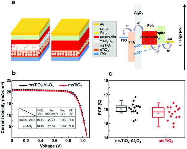
The thickness of the fabricated single mesoporous TiO2 and bilayer mesoporous TiO2/Al2O3 films is ∼150 nm and ∼300 nm, respectively (ESI,† Fig. S2). These films were used as supporting scaffolds to prepare perovskite solar cells in ambient air at >65% RH (thermal evaporation of the gold electrodes was carried out in vacuum). Fig. 1a shows the schematics of the device configurations based on different mesoporous scaffolds. The perovskite absorber is infiltrated within the mesoporous scaffold and forms a confined mesoscopic morphology covered by a compact capping layer. As illustrated by the band diagram in Fig. 1a, the Al2O3 film acts as both a supporting scaffold and a spacer between the electron and hole transporting layers (ETL, HTL). The Al2O3 spacer may block the penetration of spiro-MeOTAD or gold, thereby avoiding direct contact with TiO2, which will be further discussed below. Here, however, the main purpose of introducing the additional mesoporous Al2O3 layer is to enhance the air stability of the device by increasing the thickness of the perovskite that permeates the mesoporous scaffold. As can be seen from the band alignment diagram between perovskite and the degradation product PbI2, PbI2 has a wider bandgap than the perovskite. This implies impeded charge transfer possibly occurring as a result of PbI2 formation.9,10 We turn now to discuss the relationship between photovoltaic performance and air stability in the mesoscopic single layer- and bilayer-based PSCs.Firstly, we measured the PCE of the PSCs based on bilayer mesoporous scaffolds with a varying Al2O3 layer thickness of 50–100 nm, 150 nm, 300 nm, 500 nm and 700 nm (see ESI,† Fig. S3 and Table S1). It was found that the PCE decreases dramatically with the thickness of the Al2O3 layer >150 nm. This result is possibly due to a longer charge carrier transport distance for the PSCs based on the thicker Al2O3 layer. Due to the difficulty in preparing a uniform ultra-thin mesoscopic layer, we only obtained a mesoporous Al2O3 layer with uneven thickness ranging from 50 nm to 100 nm. The PSCs based on TiO2/Al2O3 with the Al2O3 thickness fluctuating between 50 nm and 100 nm show lower PCE than those based on the uniform bilayer mesoporous scaffold with an Al2O3 thickness of 150 nm. This is possibly due to the negative effect of the wave-like surface morphology of the mesoporous scaffold on the growth of perovskite crystals. The highest PCE for the fully ambient-processed PSC is based on the bilayer TiO2/Al2O3 mesoporous scaffold with 150 nm-thick Al2O3, with a champion PCE of 16.84% and a mean value of 16.01%. This result is slightly higher than the PCE for single TiO2 devices (champion = 16.43%, mean = 15.70%) (Fig. 1b and c).
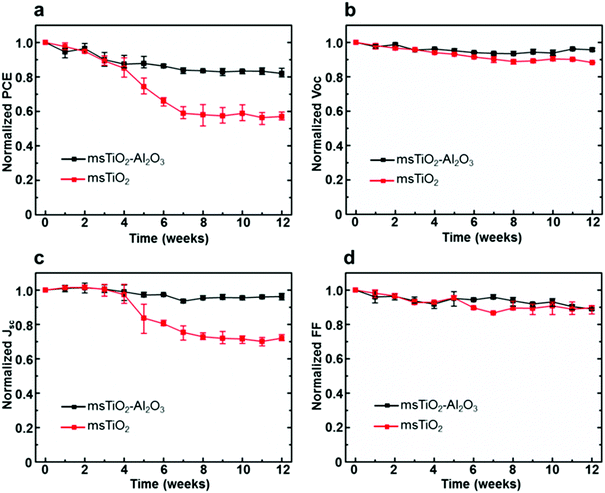
The stability of PSCs was examined by storing the devices under ambient air with a RH > 65% for 12 weeks (∼2000 h) during which the photovoltaic parameters (PCE, open-circuit voltage Voc, short-circuit current density Jsc, fill factor FF) were measured weekly. Normalized PCE, Voc, Jsc, and FF of the PSCs, based on different mesoporous scaffolds, are shown in Fig. 2a–d as a function of time. In order to obtain reliable results, each point was plotted as an average over 8 cells in the same counterparts. Fig. 2b and d show that the Voc and FF of both single and bilayer mesoporous scaffold-based PSCs decrease slightly and roughly linearly. However, a distinguishable difference for the Jsc between the two types of devices is more marked in Fig. 2c: the single mesoporous scaffold-based PSC shows a sudden drop after 4 weeks and shows a reduction of ∼30% in the Jsc after 12 weeks’ storage. The bilayer mesoporous scaffold-based PSC, on the other hand, retains ∼95% of its initial Jsc. A stable Jsc over time suggests more uniform perovskite loading in the bilayer mesoporous scaffold, which is further confirmed in our study. As a result, the PCE of the bilayer TiO2/Al2O3 mesoporous scaffold-based solar cell after 12 weeks of storage in ambient air retains 82% of its initial value, while in single TiO2 mesoporous scaffold-based device the PCE falls to 57% of the original (ESI,† Fig. S4). In addition, we also studied the stability of the single Al2O3 mesoporous scaffold-based PSCs, as shown in Fig. S5 (ESI†), where moisture instability even more significant than that for the single layer TiO2 is observed. More detailed information regarding the PCE decay of different types of PSCs can be found in Table S2 (ESI†).
The measurement of the decay of photovoltaic parameters in PSCs reveals that the additional mesoporous Al2O3 layer allows Jsc values in devices to be maintained over time, and therefore, significantly improves the long-time air stability of solar cells. It is also noteworthy that we have improved the air stability of the PSCs without any sacrifice of their initial PCE using a bilayer mesoporous scaffold, rather than a thickened single mesoporous scaffold. As a comparison, we fabricated PSCs based on the single mesoporous scaffold with various thicknesses, ranging from 100 nm to 800 nm for TiO2, and 150 nm to 700 nm for Al2O3. As shown in Fig. S6 and S7 (ESI†), all devices based on thick single mesoporous scaffolds (>150 nm) suffer from a reduced photovoltaic performance, which is consistent with previous studies.22,23 The reduced photovoltaic performance, particularly low Voc and FF, of PSCs based on the mesoporous TiO2 with thickness over 150 nm is mainly caused by the long electron transport distance in the TiO2 lattices and possible exposure of TiO2 nanoparticles to the hole transporter. In the case of PSCs based on the single mesoporous Al2O3, although electrons can move rapidly in the perovskite itself, a lack of sufficient charge extraction leads to poor photovoltaic performance. In summary, PSCs based on the TiO2/Al2O3 bilayer mesoporous scaffold yield comparable PCE and improved air stability compared to the conventional PSCs based on the single mesoporous TiO2 substrate. In order to investigate the impact of bilayer mesoscopic architecture on PSC device stability, the evolution of the phase, composition, and morphology of the perovskite layers generated on different mesoporous scaffolds was characterized and analyzed as a function of time.
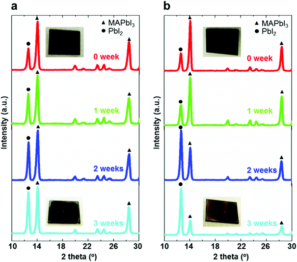
XRD measurements of the perovskite films deposited on different mesoporous scaffolds were carried out immediately after fabrication and once a week in the following three weeks. As can be seen from Fig. 3a and b, the perovskite films are composed of a combined phase of perovskite and PbI2. The intensity of the main peak (14.2°), corresponding to (110) planes of the perovskite, decreases over time, while the peak at 12.7° corresponding to PbI2(001) planes has an increasing intensity. This can be observed for both bilayer and single layer mesoporous scaffold-based perovskite films, indicating the occurrence of perovskite degradation to form PbI2 over time for both perovskite films. However, the ratio of peak intensities of (001) PbI2 to (110) perovskite based on the bilayer mesoporous scaffold grows significantly slower than that of the perovskite film based on the single mesoporous scaffold. This agrees with the observation from the colour change of the perovskite films: the aged perovskite film based on the single TiO2 mesoporous scaffold exhibits a more yellowish appearance, indicating the existence of more PbI2,38 than the perovskite film based on the TiO2/Al2O3 bilayer mesoporous scaffold. It is therefore apparent that the TiO2/Al2O3 bilayer mesoporous scaffold may reduce the degradation rate of the perovskite films during the aging test in ambient air.
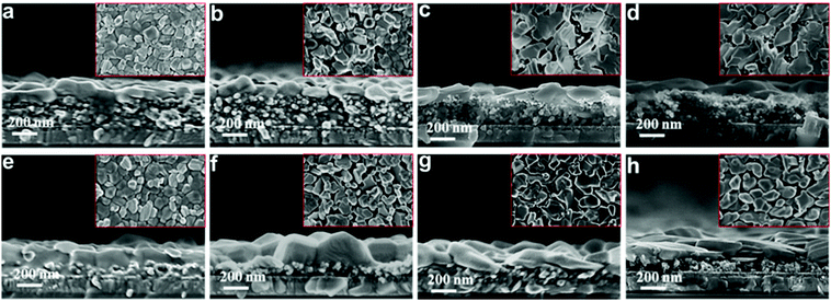
To further understand the underlying mechanisms, the morphological changes of the perovskite films were investigated via SEM. Fig. 4 shows the top and cross-sectional views of the perovskite films deposited on different mesoporous scaffolds as a function of time. It can be observed that a capping layer covers the top of the perovskite-infiltrated mesoporous scaffold. For freshly prepared perovskite films, the capping layer based on the single mesoporous scaffold is clearly much thicker than that based on the bilayer mesoporous scaffold. However, the perovskite films based on the different scaffolds have a similar overall thickness of ∼400 nm. After three weeks’ aging in ambient air, the fresh perovskite capping layer which is composed of uniform grains deforms into a stack of irregularly distributed large flakes under exposure to humid air, indicating degradation of perovskite crystals. The perovskite which penetrates the mesoporous scaffold, however, is protected from degradation by the mesoporous scaffold and maintains its initial morphology during the aging test. This is consistent with our result from the XRD measurement that the perovskite films based on the TiO2/Al2O3 bilayer mesoporous scaffold show less degradation than that of the single mesoporous TiO2 counterparts, due to a thicker mesoporous scaffold and a thinner perovskite capping layer.
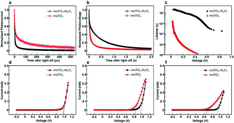
In order to study the influence of the mesoporous scaffold on charge transportation and recombination properties of the aged PSCs, photo-current and photo-voltage decay features of the aged PSCs based on different mesoporous scaffolds were studied by measuring the transient electrical response of solar cells excited using a pulsed laser. The photo-current decay is shown in Fig. 5a. The PSC based on the bilayer mesoporous scaffold exhibits an obvious fast photo-current response, whose time constant τtr-bilayer is calculated to be 2.64 μs, while a longer photo-current decay time of τtr-single = 16.5 μs is obtained from the single mesoporous layer counterpart. Since the photo-current decay feature of photovoltaic devices is highly dependent on the charge transfer rate, a prolonged photo-current decay time for the single mesoporous scaffold-based devices indicates impeded charge extraction at the ETL/perovskite/HTL interfaces. As aforementioned, the perovskite capping layer degrades rapidly in ambient air. In the case of single mesoporous scaffold-based PSCs, a large amount of PbI2 forms at the perovskite/HTL interface, producing a high density of defect states that block hole transport, thus resulting in a poorer photovoltaic performance after aging. For the photo-voltage measurements (Fig. 5b), a much faster decay (τre-single = 0.456 ms) in the single mesoporous scaffold configuration is observed. In contrast, the photo-voltage of the bilayer mesoporous scaffold-based solar cell exhibits a slow decay process with τre-double = 299 ms. As the transient photo-voltage measurement was carried out under open-circuit conditions, photo-generated electrons and holes recombine with each other, resulting in decay of the built-in voltage. Therefore, faster photo-voltage decay found in the aged PSCs based on the single mesoporous scaffold suggests a higher recombination rate, which can be understood as a shorter lifetime of the free charge carriers in the perovskite film.39 The electron lifetimes (τn) are obtained by differentiating the photovoltage decay curve according to40
Different J–V characteristics dependent on the voltage sweep direction indicate the hysteretic behavior of the PSCs,42 which can be associated with the degradation process and interfacial contacts of PSC devices.42–45 To find the role of the additional Al2O3 mesoporous layer in the hysteretic behavior in J–V characteristics of the PSCs during aging, we performed J–V scans by reverse and forward sweep directions of the PSCs based on different mesoporous scaffolds at different stages of aging, as shown in Fig. 6. The hysteresis index (HI) for PCE or for Voc is defined46 as (PCE(Voc)R − PCE(Voc)F)/PCE(Voc)R, where R or F represents reverse or forward scan, respectively. HIs for different devices are given in Fig. S8 and Table S3 (ESI†) as a function of aging time. The initial HIs for both bilayer mesoporous scaffold- and single mesoporous scaffold-based freshly prepared devices remain at a relatively low value. After aging for 12 weeks, the devices based on the single mesoporous scaffold show a more remarkable hysteresis behavior compared to the bilayer counterparts, with an HIPCE of 0.68. On the other hand, PSCs based on the TiO2/Al2O3 bilayer mesoporous scaffold show an HIPCE of only 0.17. Obvious hysteresis for PCE and for photovoltage is observed in the aged single TiO2 mesoporous scaffold-based devices, which is possibly triggered by pre-biasing conditions in the presence of ion migration and interfacial charge trapping.47 Decomposition of the perovskite into PbI2 and other products under exposure to moisture could induce high concentration of ionic defects.45,48 Consequently, increased density of mobile ions or vacancies existing in the degraded perovskite amplifies the detrimental effect of ion migration toward the electrodes. Furthermore, the presence of interfacial charge trap sites mediated by the degradation-induced ionic defects worsens the hysteresis effect in the aged devices.42,46,47 In addition, interfacial recombination mediated by TiO2 may also contribute to the notable hysteretic behavior observed in the aged devices based on the single TiO2 mesoporous scaffold. In a typical configuration of an n–i–p mesoscopic PSC, a perovskite capping layer is sandwiched between mesoporous scaffold and HTL. As the perovskite capping layer degrades, the mesoporous scaffold is gradually exposed to the perovskite/HTL interface. In the case of single TiO2 devices (ESI,† Fig. S9), the appearance of TiO2 nanoparticles in the p-type contact area increases the possibility of interfacial charge recombination between free holes and the trapped electrons in the defect states in TiO2.33 In turn, less severe hysteresis observed in the aged TiO2/Al2O3 bilayer mesoporous scaffold-based devices compared to that of the aged single TiO2 devices could indicate, to some extent, reduced formation of ionic defects and suppressed interfacial recombination by adding a mesoporous Al2O3 layer on top of mesoporous TiO2. Preventing TiO2-assisted interfacial recombination by building an interlayer of insulator, such as Al2O3 or ZrO2, between TiO2 and HTL (or electrode) has also been reported in other studies.14,20,49,50
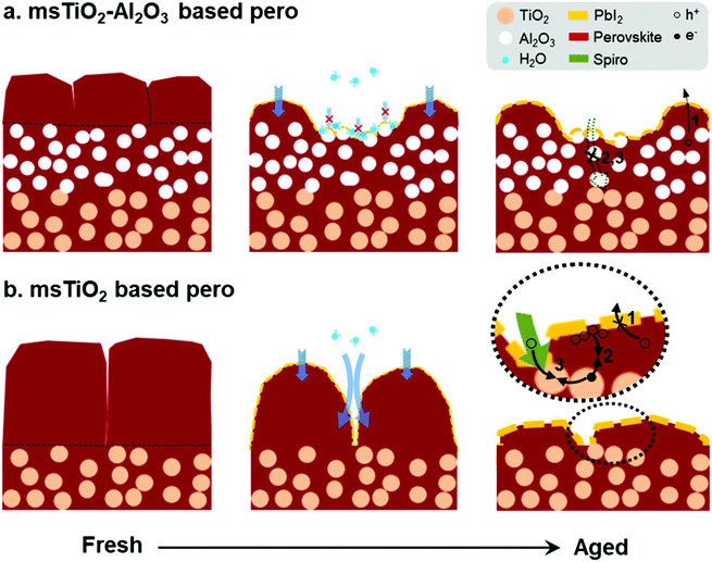
The moisture-induced mechanism for PSCs based on different mesoporous scaffolds is illustrated in Fig. 7. Since water vapor in humidified air causes decomposition of the capping layer first, the “unprotected” perovskite capping layer degrades rapidly under exposure to ambient air. Defects such as cracks or voids existing at perovskite grain boundaries allow water molecules to penetrate, accelerating the perovskite degradation. Finally, the uniform perovskite grains are completely transformed into disorganized flake-like grains covered by PbI2. After this fast decomposition of the perovskite capping layer, water penetration slows down due to the presence of the mesoscopic layer, as shown in Fig. 7a. The mesoscopic framework substantially promotes the nucleation and growth of the infiltrated perovskite crystals and thus the pore-filling factor.51 Therefore, the perovskite layer within the mesoscopic framework remains in a dense morphology for a longer period of time than the capping layer, and acts as a barrier against water ingress during the aging test. In addition, the water-absorbing mesoscopic surface can retain water20 and prevent further water penetration into the deep sites. Due to the slower degradation rate occurring in the perovskite within the mesoporous scaffold, the bilayer mesoporous scaffold with increased thickness relative to the single mesoporous scaffold can load more perovskite, ensuring a more stable photovoltaic performance of the PSCs. On the other hand, as shown in Fig. 7b, a ∼250 nm-thick perovskite capping layer generated on the single mesoporous scaffold degrades into a large amount of PbI2 accumulating at the external surface, which may seriously hinder the transport of the holes to the HTL (route 1). While the TiO2 nanoparticles are exposed to the perovskite/HTL interface, the accumulated holes at the interface or the free holes in the HTL may recombine with the trapped electrons in the electronic trap states of TiO2 (route 2 or 3).33 In the case of a bilayer mesoporous scaffold, the charge transfer rate is less likely to suffer a significant reduction because of the reduced PbI2 formation at the interface. In addition, the existence of a layer of Al2O3 insulator effectively prevents direct contact at the interface between ETL and HTL (or charge carrier accumulations), particularly when the perovskite capping layer has failed to do so due to its severe degradation. Therefore, for the aged PSCs, devices based on the TiO2/Al2O3 bilayer mesoporous scaffold show a reduced possibility of charge recombination and current leakage at the interface, as well as less severe hysteretic behavior, in comparison to the PSCs based on the single TiO2 mesoporous scaffold.
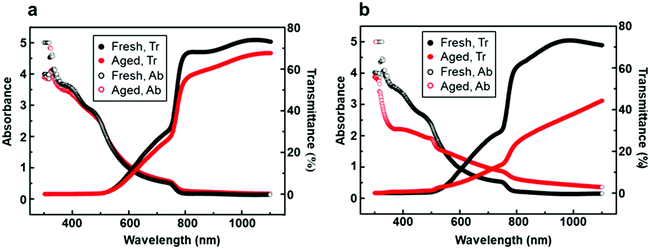
Besides long-term air stability, transmittance is another important indicator to evaluate perovskite solar cells.52 One of the advantages of PSCs is their semi-transparent feature over the visible light range (380–740 nm), which enables the possibility of fabricating tandem solar cells to utilize solar energy more fully. UV-visible spectroscopy of perovskite films generated on the bilayer mesoporous scaffold (Fig. 8a) and on the single mesoporous scaffold (Fig. 8b) was performed under incident light wavelengths ranging from 300 nm to 1100 nm. The average visible transmittance (AVT) of the perovskite film generated on the bilayer mesoporous scaffold slightly decreases from 9.48% to 7.97% after aging, still preserving the semi-transparent feature. In contrast, a distinct decrease of the AVT from 9.52% to 4.64% is found in the aged perovskite film based on the single mesoporous scaffold. As Fig. 4 demonstrates, the perovskite film based on the single mesoporous scaffold suffers severe degradation. During the degradation process, the smooth perovskite capping layer composed of neatly arranged large grains is transformed into a stack of unorganized flakes. The high volume of “new-born” grain boundaries and rough surfaces scatter incident light, leading to poor light transmittance. For the perovskite film based on the bilayer scaffold, the Al2O3 layer introduces no reduction in light transmittance due to the similar overall thickness between fresh perovskite films based on different mesoporous scaffolds. During the aging test, the perovskite film based on the bilayer mesoporous scaffold shows a smaller change in morphology as well as a more stable light transmission over time compared to the single mesoporous scaffold.
Conclusions
In this work, we have fabricated a TiO2/Al2O3 bilayer mesoporous scaffold for perovskite solar cells with a specific focus on enhancing the air stability of the devices. Based on the TiO2/Al2O3 bilayer mesoporous scaffold, stable and efficient perovskite solar cells were produced and stored under ambient conditions at a RH of over 65%, delivering 16.84% initial PCE. Over 80% of the initial PCE was retained after 2000 h. The improved air stability of PSCs is mainly attributed to a reduced degradation rate of the perovskite absorber by introducing an additional mesoporous Al2O3 scaffold, which can protect more of the infiltrated perovskite from attack by moisture. More stable perovskite within the mesoscopic layer ensures an adequate yield of photo-generated charge carriers and thereby a more stable photovoltaic performance of the PSCs over time. In addition, the existence of an additional Al2O3 layer can mitigate the charge transportation property deterioration due to the perovskite degradation. Furthermore, the perovskite film based on the TiO2/Al2O3 bilayer mesoporous scaffold shows comparable and more stable light transmission than the perovskite film based on a single TiO2 mesoporous scaffold, indicating its potential to be used in tandem PSC applications. Our research proposes a promising approach using a well-designed TiO2/Al2O3 bilayer mesoscopic architecture towards the fabrication of stable and efficient PSCs.Conflicts of interest
There are no conflicts to declare.Acknowledgements
Dong Wang acknowledges the financial support by the State Scholarship Fund under the auspices of the China Scholarship Council (No. 201706120028). The authors particularly thank Dr John E. Warren for his help with XRD characterization.Notes and references
- J. Cao, C. Li, X. Lv, X. Feng, R. Meng, Y. Wu and Y. Tang, J. Am. Chem. Soc., 2018, 140, 11577–11580 CrossRef CAS.
- N. Aristidou, I. Sanchez-Molina, T. Chotchuangchutchaval, M. Brown, L. Martinez, T. Rath and S. A. Haque, Angew. Chem., Int. Ed., 2015, 54, 8208–8212 CrossRef CAS.
- B. Conings, J. Drijkoningen, N. Gauquelin, A. Babayigit, J. D’Haen, L. D’Olieslaeger, A. Ethirajan, J. Verbeeck, J. Manca, E. Mosconi, F. D. Angelis and H.-G. Boyen, Adv. Energy Mater., 2015, 5, 1500477 CrossRef.
- J. A. Christians, P. A. Miranda Herrera and P. V. Kamat, J. Am. Chem. Soc., 2015, 137, 1530–1538 CrossRef CAS.
- J. C.-R. Ke, A. S. Walton, D. J. Lewis, A. Tedstone, P. O’Brien, A. G. Thomas and W. R. Flavell, Chem. Commun., 2017, 53, 5231–5234 RSC.
- J. Zhang, T. Song, Z. Zhang, K. Ding, F. Huang and B. Sun, J. Mater. Chem. C, 2015, 3, 4402–4406 RSC.
- L. Wang, C. McCleese, A. Kovalsky, Y. Zhao and C. Burda, J. Am. Chem. Soc., 2014, 136, 12205–12208 CrossRef CAS.
- Q. Chen, H. Zhou, T.-B. Song, S. Luo, Z. Hong, H.-S. Duan, L. Dou, Y. Liu and Y. Yang, Nano Lett., 2014, 14, 4158–4163 CrossRef CAS.
- Y. H. Lee, J. Luo, R. Humphry-Baker, P. Gao, M. Grätzel and M. K. Nazeeruddin, Adv. Funct. Mater., 2015, 25, 3925–3933 CrossRef CAS.
- H. Xu, Y. Wu, J. Cui, C. Ni, F. Xu, J. Cai, F. Hong, Z. Fang, W. Wang, J. Zhu, L. Wang, R. Xu and F. Xu, Phys. Chem. Chem. Phys., 2016, 18, 18607–18613 RSC.
- W. Veiga and C. M. Lepienski, Mater. Sci. Eng., A, 2002, 335, 6–13 CrossRef.
- M. Wang, X. Jiang, J. Bian, Y. Feng, C. Wang, Y. Huang, Y. Zhang and Y. Shi, ACS Appl. Mater. Interfaces, 2019, 11, 2989–2996 CrossRef CAS.
- M. Z. Mokhtar, Q. Chen, Q. Lian, D. J. Lewis, B. R. Saunders, A. S. Walton, C.-R. Ke, E. Whittaker, B. Hamilton and S. Haque, ACS Appl. Energy Mater., 2018, 1, 5567–5578 CrossRef CAS.
- S. Guarnera, A. Abate, W. Zhang, J. M. Foster, G. Richardson, A. Petrozza and H. J. Snaith, J. Phys. Chem. Lett., 2015, 6, 432–437 CrossRef CAS.
- M. M. Tavakoli, P. Yadav, R. Tavakoli and J. Kong, Adv. Energy Mater., 2018, 8, 1800794 CrossRef.
- E. Y. Choi, J. Kim, S. Lim, E. Han, A. W. Y. Ho-Baillie and N. Park, Sol. Energy Mater. Sol. Cells, 2018, 188, 37–45 CrossRef CAS.
- Y. I. Lee, N. J. Jeon, B. J. Kim, H. Shim, T.-Y. Yang, S. I. Seok, J. Seo and S. G. Im, Adv. Energy Mater., 2018, 8, 1701928 CrossRef.
- Y. Wang, W.-Y. Rho, H.-Y. Yang, T. Mahmoudi, S. Seo, D.-H. Lee and Y.-B. Hahn, Nano Energy, 2016, 27, 535–544 CrossRef CAS.
- Y. Wang, T. Mahmoudi, W.-Y. Rho and Y.-B. Hahn, Nano Energy, 2019, 64, 103964 CrossRef CAS.
- A. Mei, X. Li, L. Liu, Z. Ku, T. Liu, Y. Rong, M. Xu, M. Hu, J. Chen, Y. Yang, M. Grätzel and H. Han, Science, 2014, 345, 295–298 CrossRef CAS.
- K. Cao, Z. Zuo, J. Cui, Y. Shen, T. Moehl, S. M. Zakeeruddin, M. Grätzel and M. Wang, Nano Energy, 2015, 17, 171–179 CrossRef CAS.
- J. Yang, K. M. Fransishyn and T. L. Kelly, Chem. Mater., 2016, 28, 7344–7352 CrossRef CAS.
- J. Yin, J. Cao, X. He, S. Yuan, S. Sun, J. Li, N. Zheng and L. Lin, J. Mater. Chem. A, 2015, 3, 16860–16866 RSC.
- A. Fakharuddin, F. Di Giacomo, I. Ahmed, Q. Wali, T. M. Brown and R. Jose, J. Power Sources, 2015, 283, 61–67 CrossRef CAS.
- M. H. Kumar, N. Yantara, S. Dharani, M. Grätzel, S. Mhaisalkar, P. P. Boix and N. Mathews, Chem. Commun., 2013, 49, 11089–11091 RSC.
- W. Geng, C.-J. Tong, J. Liu, W. Zhu, W.-M. Lau and L.-M. Liu, Sci. Rep., 2016, 6, 20131 CrossRef CAS.
- P. Tiwana, P. Docampo, M. B. Johnston, H. J. Snaith and L. M. Herz, ACS Nano, 2011, 5, 5158–5166 CrossRef CAS.
- H.-S. Kim, I.-H. Jang, N. Ahn, M. Choi, A. Guerrero, J. Bisquert and N.-G. Park, J. Phys. Chem. Lett., 2015, 6, 4633–4639 CrossRef CAS.
- Y. Zhang, M. Liu, G. E. Eperon, T. C. Leijtens, D. McMeekin, M. Saliba, W. Zhang, M. de Bastiani, A. Petrozza, L. M. Herz, M. B. Johnston, H. Lin and H. J. Snaith, Mater. Horiz., 2015, 2, 315–322 RSC.
- F. T. F. O’Mahony, Y. H. Lee, C. Jellett, S. Dmitrov, D. T. J. Bryant, J. R. Durrant, B. C. O’Regan, M. Grätzel, M. K. Nazeeruddin and S. A. Haque, J. Mater. Chem. A, 2015, 3, 7219–7223 RSC.
- H.-S. Kim, C.-R. Lee, J.-H. Im, K.-B. Lee, T. Moehl, A. Marchioro, S.-J. Moon, R. Humphry-Baker, J.-H. Yum, J. E. Moser, M. Grätzel and N.-G. Park, Sci. Rep., 2012, 2, 591 CrossRef.
- G. S. Han, H. S. Chung, D. H. Kim, B. J. Kim, J.-W. Lee, N.-G. Park, I. S. Cho, J.-K. Lee, S. Lee and H. S. Jung, Nanoscale, 2015, 7, 15284–15290 RSC.
- T. Leijtens, G. E. Eperon, S. Pathak, A. Abate, M. M. Lee and H. J. Snaith, Nat. Commun., 2013, 4, 2885 CrossRef.
- M. M. Lee, J. Teuscher, T. Miyasaka, T. N. Murakami and H. J. Snaith, Science, 2012, 338, 643–647 CrossRef CAS.
- Q. Wang, S. Liu, Y. Ming, Y. Guan, D. Li, C. Zhang, Z. Wang, Y. Rong, Y. Hu and H. Han, Sustainable Energy Fuels, 2018, 2, 2412–2418 RSC.
- Q. Chen, M. Z. Mokhtar, J. C.-R. Ke, A. G. Thomas, A. Hadi, E. Whittaker, M. Curioni and Z. Liu, Sustainable Energy Fuels, 2018, 2, 1216–1224 RSC.
- J. Troughton, K. Hooper and T. M. Watson, Nano Energy, 2017, 39, 60–68 CrossRef CAS.
- G. Niu, W. Li, F. Meng, L. Wang, H. Dong and Y. Qiu, J. Mater. Chem. A, 2014, 2, 705–710 RSC.
- Z. Liu, B. Sun, T. Shi, Z. Tang and G. Liao, J. Mater. Chem. A, 2016, 4, 10700–10709 RSC.
- X. Gao, J. Li, J. Baker, Y. Hou, D. Guan, J. Chen and C. Yuan, Chem. Commun., 2014, 50, 6368–6371 RSC.
- J. Cui, F. Meng, H. Zhang, K. Cao, H. Yuan, Y. Cheng, F. Huang and M. Wang, ACS Appl. Mater. Interfaces, 2014, 6, 22862–22870 CrossRef CAS.
- R. T. Ginting, M.-K. Jeon, K.-J. Lee, W.-Y. Jin, T.-W. Kim and J.-W. Kang, J. Mater. Chem. A, 2017, 5, 4527–4534 RSC.
- P. Calado, A. M. Telford, D. Bryant, X. Li, J. Nelson, B. C. O’Regan and P. R. F. Barnes, Nat. Commun., 2016, 7, 13831 CrossRef CAS.
- Y. Zhang, M. Liu, G. E. Eperon, T. C. Leijtens, D. McMeekin, M. Saliba, W. Zhang, M. de Bastiani, A. Petrozza, L. M. Herz, M. B. Johnston, H. Lin and H. J. Snaith, Mater. Horiz., 2015, 2, 315–322 RSC.
- W. Tress, N. Marinova, T. Moehl, S. M. Zakeeruddin, M. K. Nazeeruddin and M. Grätzel, Energy Environ. Sci., 2015, 8, 995–1004 RSC.
- J. Hong, H. Kim and I. Hwang, J. Mater. Chem. C, 2019, 7, 1173–1181 RSC.
- S. van Reenen, M. Kemerink and H. J. Snaith, J. Phys. Chem. Lett., 2015, 6, 3808–3814 CrossRef CAS.
- E. C. Smith, C. L. C. Ellis, H. Javaid, L. A. Renna, Y. Liu, T. P. Russel, M. Bag and D. Venkataraman, J. Phys. Chem. C, 2018, 122, 13986–13994 CrossRef CAS.
- M. Xu, Y. Rong, Z. Ku, A. Mei, T. Liu, L. Zhang, X. Li and H. Han, J. Mater. Chem. A, 2014, 2, 8607–8611 RSC.
- Y. Wang, T. Mahmoudi, H.-Y. Yang, K. S. Bhat, J.-Y. Yoo and Y.-B. Hahn, Nano Energy, 2018, 49, 59–66 CrossRef CAS.
- N. Islam, M. Yang, K. Zhu and Z. Fan, J. Mater. Chem. A, 2015, 3, 24315–24321 RSC.
- C. Dokkhan, M. Z. Mokhtar, C.-R. Ke, A. S. Walton, Q. Chen, N. W. Hodson, Q. Lian and B. R. Saunders, ACS Appl. Energy Mater., 2019, 2, 6624–6633 CrossRef CAS.
Footnote |
| † Electronic supplementary information (ESI) available: Relative humidity (RH); SEM images of mesoporous scaffolds; PV performances of the PSCs based on different mesoporous scaffolds with varying thickness; air stability of the PSCs based on different mesoporous scaffolds; hysteresis behavior shown in the aged PSCs based on different mesoporous scaffolds. See DOI: 10.1039/d0ma00562b |
| This journal is © The Royal Society of Chemistry 2020 |

