2,2′-Bis(3-hydroxy-1,4-naphthoquinone)/CMK-3 nanocomposite as cathode material for lithium-ion batteries†
Hao
Li
,
Wenchao
Duan
,
Qing
Zhao
,
Fangyi
Cheng
,
Jing
Liang
and
Jun
Chen
*
Key Laboratory of Advanced Energy Materials Chemistry (Ministry of Education), College of Chemistry, Collaborative Innovation Center of Chemical Science and Engineering, Nankai University, Tianjin 300071, P. R. China. E-mail: chenabc@nankai.edu; Fax: +86-22-23509571; Tel: +86-22-23506808
First published on 28th January 2014
Abstract
An inorganic–organic nanocomposite with the filling of 2,2′-bis(3-hydroxy-1,4-naphthoquinone) (H2bhnq) in the pores of CMK-3 mesoporous carbon, which was synthesized by a simple impregnation method, was employed as a new cathode material for rechargeable lithium-ion batteries (LIBs). The characterization of the nanocomposite by wide-angle and low-angle X-ray diffraction, Brunauer–Emmett–Teller (BET), scanning electron microscopy (SEM) and transmission electron microscopy (TEM) showed the efficient loading of H2bhnp within the nanosized pores of CMK-3 carbon. The nanocomposite delivered an initial discharge capacity of 308.6 mAh g−1 at 0.1 C rate and a capacity retention of 202.6 mAh g−1 after 50 cycles. The reversible capacities were 124.0 mAh g−1 at a higher rate of 10 C. The enhanced cycling stability and high-rate capability is attributed to the fact that neat H2bhnq was distributed in the nanochannels of the conductive carbon framework CMK-3. This constrains the dissolution of the embedded H2bhnq. The results imply that the nanoconfinement with the pores of inorganic materials such as CMK-3 to fill organic active materials is important to improve the electrochemical performance of lithium-ion batteries.
Introduction
Lithium-ion batteries (LIBs) are representative electrochemical energy storage and conversion devices to power portable electronics. For applications in the emerging fields of electric vehicles (EV) and smart grids, there is an increasing requirement of improved safety, lower cost and higher energy density.1–3 Organic carbonyl compounds have attracted extensive attention as alternative active materials for LIBs due to their wide availability, environmentally-benign synthesis, high theoretical capacity and structural flexibility.4–8 Unfortunately, the liable dissolution of small organic molecules in aprotic electrolyte and the intrinsically poor electrical conductivity of organic compounds usually lead to rapid capacity fading and a lower rate capability, severely hindering their practical application.Several innovative strategies have been attempted to address the solubility problem of organic compounds in electrolytes, including increasing the molecular weight by polymerization,9–14 fabricating coordination compounds through Li–O or Li–N bond bridges15–18 and using a solid or quasi-solid-state electrolyte to replace the traditional liquid electrolyte.19,20 On the other hand, two common approaches have been used to enhance the electrical conductivity of organic electrodes. One is the incorporation of heteroaromatic structures in organic molecular frameworks21 while the other is resorting the active materials to conductive additives such as carbon nanostructures.22–25 Recently, a composite of 9,10-anthraquinone (AQ) and mesoporous carbon has been proposed to simultaneously overcome the dissolution and poor conductivity issue of AQ,26 resulting in an improved cycle life and rate performance. Nevertheless, the relatively large open porous structure (with pore diameter of 50–60 nm) of the employed carbon cannot effectively prevent the dissolution of AQ in the electrolyte and thus only a limited capacity of 97 mAh g−1 has been maintained after 50 cycles for the composite electrode. An appropriate mesoporous carbon matrix with a smaller pore diameter for better confining organic material is desirable to attain an enhanced electrode performance.
Mesoporous CMK-3 carbon has been extensively investigated for potential applications such as catalyst support, hydrogen storage, supercapacitors and Li-S batteries,27–29 owning to its well-ordered porous structure, uniform small pore size (6–7 nm), large specific surface area and high conductivity.30 These properties of CMK-3 should make it a suitable matrix for loading soluble organic electrode materials. In this work, we apply CMK-3 to confine 2,2′-bis(3-hydroxy-1,4-naphthoquinone) (H2bhnq). As a flexible hinge like ligand, H2bhnq has been widely used in coordination chemistry to construct metal–organic frameworks.31,32 However, to the best of our knowledge, it has not been reported for use in LIBs. Theoretically, H2bhnq could react with four Li per molecule, giving a high specific capacity of 309.6 mAh g−1 (Scheme 1a). Herein, we encapsulate H2bhnq in CMK-3 by a simple room-temperature impregnation method and demonstrate that the as-synthesized nanocomposite exhibits a respectable lithium-storage performance (Scheme 1b). It is found that the hurdles of poor conductivity and easy dissolution of H2bhnq in the aprotic electrolyte can be largely surmounted owing to the restriction of the nanoporous structure and the high electrical conductivity of the carbon framework.
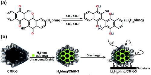 | ||
| Scheme 1 A schematic illustration for (a) the proposed electrochemical redox mechanism of H2bhnq and (b) the preparation and electrode reaction of the H2bhnq/CMK-3 nanocomposite. | ||
Experimental
Synthesis
All reagents are of analytic grade unless stated. H2bhnq was synthesized by an oxidization method (Scheme S1, ESI†).33 In a typical synthesis, 1 mmol bi-1,4-naphthoquinone was dissolved in 5 mL 1,4-dioxane and 0.75 mL aqueous NaOH solution (5 mol L−1). Five drops of aqueous H2O2 (30%) were then added to the obtained suspension, forming a clear red solution. The mixture was vigorously stirred for 5 min and the insoluble reagent was filtered off. After the evaporation of the filtrate, the residue was recrystallized from glacial acetic acid to generate yellow amorphous powders (0.242 g, 70% yield).The H2bhnq/CMK-3 nanocomposite was prepared by a simple impregnation method. H2bhnq (50 mg) was first dissolved in 1 mL dimethyl sulfoxide (DMSO) and 50 mg CMK-3 (purchased from Nanjing JiCang) was then added to the solution. The mixture was ultrasonically treated for 30 min. After that, the solvent was removed under vacuum to obtain the H2bhnq/CMK-3 nanocomposite. Samples with different compositions were also prepared by altering the mass ratio of H2bhnq and CMK-3.
Material characterization
The structures of H2bhnq were determined by 1H and 13C nuclear magnetic resonance spectroscopy (NMR, Varian Mercury Vx300 MHz spectrometer) and elemental analysis (German, VarioEL). The IR spectra were collected at room temperature using a FTIR-650 spectrometer (Tianjin Gangdong) between 4000 and 400 cm−1. The TG measurements were performed under an Ar atmosphere with a NETZSCH TG 209 using a heating rate of 5 °C min−1. The obtained H2bhnq/CMK-3 composites were characterized by powder X-ray diffraction in the wide 2θ range of 10–80° (Rigaku MiniFlex600, CuKα radiation) and in the small 2θ range of 0.6–6° (Bruker D8FOCUS, CuKα radiation). The morphologies and microstructures of the materials were observed using scanning electron microscopy (SEM, JEOL JSM7500F) and transmission electron microscopy (TEM, Philips Tecnai-F20). The surface area and pore size distribution were measured by N2 adsorption–desorption isotherms at 77 K on a BELSORP-mini instrument.Electrochemical investigation
CR2032 coin-type cells with a lithium plate anode were assembled in a glovebox filled with argon. The composite electrodes were made by blending 80 wt% H2bhnq/CMK-3 (mass ratio = 1![[thin space (1/6-em)]](https://www.rsc.org/images/entities/char_2009.gif) :
:![[thin space (1/6-em)]](https://www.rsc.org/images/entities/char_2009.gif) 1) with 10 wt% of carbon black (Vulcan XC72, Cabot) and 10 wt% of polyvinylidenedifluoride (PVDF) as a binder. The comparative H2bhnq electrodes were composed of 40 wt% H2bhnq, 50 wt% carbon black and 10 wt% PVDF. The electrolyte contained 1 M LiFP6 in ethylene carbonate–dimethyl carbonate (EC–DMC, volume ratio 1
1) with 10 wt% of carbon black (Vulcan XC72, Cabot) and 10 wt% of polyvinylidenedifluoride (PVDF) as a binder. The comparative H2bhnq electrodes were composed of 40 wt% H2bhnq, 50 wt% carbon black and 10 wt% PVDF. The electrolyte contained 1 M LiFP6 in ethylene carbonate–dimethyl carbonate (EC–DMC, volume ratio 1![[thin space (1/6-em)]](https://www.rsc.org/images/entities/char_2009.gif) :
:![[thin space (1/6-em)]](https://www.rsc.org/images/entities/char_2009.gif) 1). The charge–discharge experiments were carried out on a Land CT2001A cell testing system within the potential range of 1.8–3.3 V using different current rates. The capacities were calculated by only considering the active mass of the working electrodes as the carbon additive contributed negligibly to the overall capacity. Impedance measurements were conducted using a 2273 potentiostat/galvanostat workstation with an amplitude of 5 mV over the frequency range from 100 kHz to 100 mHz. All of the electrochemical tests were performed at room temperature.
1). The charge–discharge experiments were carried out on a Land CT2001A cell testing system within the potential range of 1.8–3.3 V using different current rates. The capacities were calculated by only considering the active mass of the working electrodes as the carbon additive contributed negligibly to the overall capacity. Impedance measurements were conducted using a 2273 potentiostat/galvanostat workstation with an amplitude of 5 mV over the frequency range from 100 kHz to 100 mHz. All of the electrochemical tests were performed at room temperature.
Results and discussion
Material characterization
The elemental analysis, IR, 1H and 13C NMR spectra (Fig. S1, S2 ESI†) of the obtained sample clearly indicate the successful synthesis of the target H2bhnq. From the result of the thermogravimetric analysis (Fig. S3, ESI†), H2bhnq exhibits a considerable thermal stability up to around 260 °C, which is an advantageous factor concerning the safety of organic electrode materials. The H2bhnq/CMK-3 nanocomposites were prepared by a simple impregnation method using a DMSO solvent. The interconnected mesoporous framework and high thermal stability of CMK-3 as well as the excellent solubility of H2bhnq in DMSO allow for both the high dispersion and high loading of H2bhnq.27,29,30Fig. 1 shows the wide-angle and low-angle XRD patterns of H2bhnq, CMK-3 and the H2bhnq/CMK-3 nanocomposite with a varied content of H2bhnq. As shown in Fig. 1a, no sharp diffraction peaks of H2bhnq can be observed when the weight ratio of H2bhnq was lower than 50%, which indicates that H2bhnq is highly dispersed in the pores of CMK-3 at the nanoscale.26,29 Such a highly dispersed amorphous state could improve the electrical conductivity of the composite. On further increasing the H2bhnq content, the peaks of H2bhnq gradually emerge, demonstrating the mixed state of the amorphous and crystalline structures in the composite.26,34 The low-angle XRD patterns in the 2θ range of 0.6–6° (Fig. 1b) display a similar trend. The sharp peak assigned to CMK-3 at 1.3° gradually declines as the content of H2bhnq is increased and disappears when the amount of H2bhnq is higher than 50 wt%, further proving the filling of the channels with H2bhnq.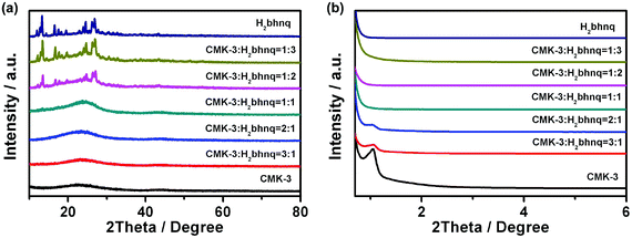 | ||
| Fig. 1 (a) The wide-angle and (b) low-angle XRD patterns of CMK-3, H2bhnp, and the H2bhnq/CMK-3 composites with different amounts of H2bhnq. | ||
The specific surface areas of CMK-3 and a representative H2bhnq/CMK-3 (mass ratio = 1![[thin space (1/6-em)]](https://www.rsc.org/images/entities/char_2009.gif) :
:![[thin space (1/6-em)]](https://www.rsc.org/images/entities/char_2009.gif) 1) composite were characterized by N2 adsorption–desorption isotherms (Fig. 2a) and the corresponding pore size distribution (PSD, Fig. 2b) was determined using the BJH method. After the impregnation of H2bhnq, the BET surface area decreases from 1084.5 to 54.9 m2 g−1, while the mesoporous volume drops from 1.09 to 0.20 cm3 g−1. These results provide further evidence to support the fact that the H2bhnq molecules were accommodated in the mesopores of CMK-3.34
1) composite were characterized by N2 adsorption–desorption isotherms (Fig. 2a) and the corresponding pore size distribution (PSD, Fig. 2b) was determined using the BJH method. After the impregnation of H2bhnq, the BET surface area decreases from 1084.5 to 54.9 m2 g−1, while the mesoporous volume drops from 1.09 to 0.20 cm3 g−1. These results provide further evidence to support the fact that the H2bhnq molecules were accommodated in the mesopores of CMK-3.34
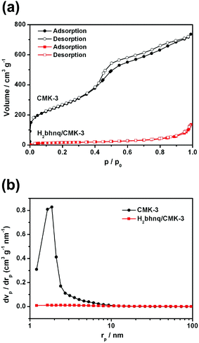 | ||
Fig. 2 (a) The nitrogen adsorption–desorption isotherms and (b) the corresponding pore-size distributions of CMK-3 and H2bhnq/CMK-3 (mass ratio = 1![[thin space (1/6-em)]](https://www.rsc.org/images/entities/char_2009.gif) : :![[thin space (1/6-em)]](https://www.rsc.org/images/entities/char_2009.gif) 1). 1). | ||
The morphology change of CMK-3 before and after impregnation is investigated using SEM. CMK-3 materials have an extremely high surface area and a highly ordered porous structure, which give them the appearance of nanochanneled carbon scaffolds (Fig. 3a).28,30 However, after impregnation of 50 wt% H2bhnq, the surface of CMK-3 turns smooth (Fig. 3b), indicating the filling of H2bhnq in the nanochannels of CMK-3. Moreover, when the content of H2bhnq reached higher than 50 wt%, the excess bulk H2bhnq was presented in the form of crystals, as can be clearly seen in the SEM image (Fig. S4, ESI†). This indicates that the channel of CMK-3 was fully filled, which is in conformity with the wide-angle XRD results. The filling of the carbon channels with H2bhnq was further verified by a TEM image. Uniform channels with a diameter of 6–7 nm are evident in the TEM image of pure CMK-3 (Fig. 3c) but largely vanish after impregnation (Fig. 3d). More importantly, no bulk H2bhnq particles were observed on the external surface, which suggests that the incorporation of H2bhnq is restricted to the inner pores of CMK-3.34
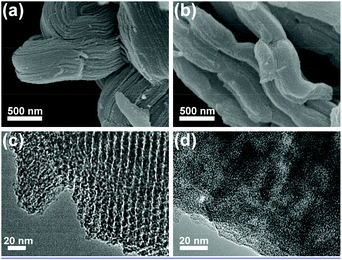 | ||
| Fig. 3 SEM images (a,b) and TEM images (c,d) of CMK-3 (a,c) and H2bhnq/CMK-3 with 50 wt% H2bhnq (b,d). | ||
Based on the above results, the H2bhnq molecules were successfully anchored into the pore channels of CMK-3 ordered mesoporous carbon through the facile impregnation method. When the mass ratio of H2bhnq reaches 50%, the pores are almost fully filled. The density of H2bhnq is 1.50 g cm−3. The pore volume of CMK-3 is 1.09 cm3 g−1, according to the BET test. It is noted that a maximum of 1.63 g (ms = vp × ρH2bhnq) of H2bhnq can be impregnated into the pores of 1.00 g of CMK-3. The weight ratio of H2bhnq was adjusted to be less than 62% to provide a transport pathway for the Li+ ions and to allow for the expansion of the pore content on full lithiation to Li4H2bhnq. Thus, the synthesized H2bhnq/CMK-3 composite with 50 wt% H2bhnq (denoted as H2bhnq/CMK-3 hereafter) was selected as a cathode material for the electrochemical test.
Electrochemical performance
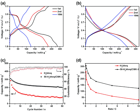
Fig. 4a–b shows the charge and discharge curves of the neat H2bhnq and the H2bhnq/CMK-3 composite. Different capacity–voltage profiles can be observed. For H2bhnq, the discharge curve has a flat voltage plateau at about 2.95 V, which is followed by relatively slopping plateaus. The average charge and discharge voltages are 2.53 and 2.36 V, respectively. The H2bhnq/CMK-3 composite electrode exhibits slopping charge–discharge curves without an apparent plateaus and with average charge–discharge voltages of 2.48/2.30 V. This feature of the charge–discharge curves suggests the prominent nanosize effect35,36 on the electrochemical behaviour of H2bhnq that is confined in the nanosized channel of the carbon scaffold. The initial discharge capacities of H2bhnq and the nanocomposite are 285.6 and 308.6 mAh g−1, respectively. The latter capacity is extremely close to the theoretical value of 309.6 mAh g−1, demonstrating that the use of the CMK-3 scaffold enables the full utilization of H2bhnq, of which each carbonyl functional group reacts with one lithium to form a lithium enolate (Scheme 1). Meanwhile, H2bhnq displays a high-specific energy of 715 W h kg−1 (based on the mass of active materials), which is compared favourably to other organic carbonyl compounds.24The cycling performance of the electrodes made with H2bhnq and H2bhnq/CMK-3 is measured at 0.1 C rate. As shown in Fig. 4c, the capacity of H2bhnq decreases rapidly after the first cycle. After 50 cycles, the discharge capacity only remains at 75.2 mAh g−1, corresponding to a capacity fading of 73.7%. The poor cycling stability is ascribed to the dissolution of H2bhnq into the electrolyte,11 which is confirmed by the fact that the electrolyte turns red after charge–discharge testing. However, a much better stability upon cycling has been observed for H2bhnq/CMK-3. After 50 cycles, a much higher capacity of 202.6 mAh g−1 is maintained. Meanwhile, the initial charge–discharge Coulombic efficiency of the composite is 85.9%, which is higher than that of H2bhnq (81.5%). After several cycles, the Coulombic efficiency can reach higher than 99%. All the results illustrate that the encapsulation of H2bhnq into CMK-3 could effectively inhibit the dissolution of H2bhnq and thus improves its cycle stability.
The rate performance of H2bhnq and H2bhnq/CMK-3 was also tested (Fig. 4d). Compared to neat H2bhnq, the composite sample exhibited a much better rate capability. The discharge capacities at 0.5 C are 154.3 and 245.8 mAh g−1 for H2bhnq and H2bhnq/CMK-3, respectively. At a high rate of 10 C, for which the electronic conductivity of the electrode materials is crucial,21–24 the discharge capacity of the nanocomposite is approximately 4 times higher than that of H2bhnq. The improved rate performance of the composite derives from the high conductivity and the ordered porous channels of CMK-3, which ensure the facile electron and ion transport.37
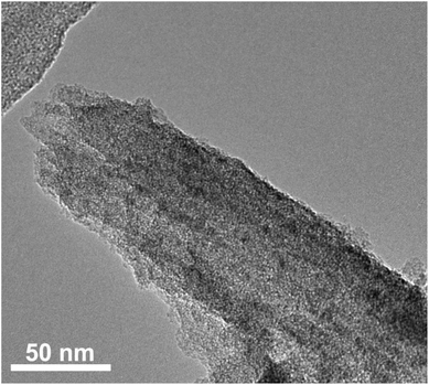
To further understand the role of CMK-3 in the composite, the structure of the electrode materials after the charge–discharge cycles was characterized by SEM and TEM. The SEM images (Fig. S5, ESI†) show that the morphology of CMK-3 was essentially preserved after the charge–discharge progress, suggesting the high structural stability of CMK-3. This could guarantee the integrity of the composite electrode during the electrochemical test. The TEM image of the nanocomposite after 50 cycles also shows a rodlike morphology (Fig. 5), which is in good agreement with the SEM result. It should be noted that no porous channel structure can be observed on the composite sample, implying that H2bhnq is well confined within the pores of CMK-3 during the whole charge–discharge process, consequently prolonging the cycle life of the composite electrode.
In order to analyze the difference of the rate properties between H2bhnq and H2bhnq/CMK-3, the impedance spectra of the two electrodes after different cycles were collected (Fig. 6). All of the profiles show a semicircle in the high-frequency regions and an inclined line in the low-frequency region. The semicircle can be assigned to the combination of the charge-transfer resistances at the electrode surface and the double-layer capacitance between the electrolyte and the cathode.38,39 The impedances increase with the cycle number for the first several cycles and then decrease for both samples. This phenomenon is relevant to the dissolution of active materials and agrees well with the previous report.26 It is worth noting that the charge transfer resistance of H2bhnq is much higher than that of the nanocomposite at the same cycle, indicating that the conductivity can be greatly enhanced after the uniform dispersion of H2bhnq in the CMK-3 nanopores owing to the high conductivity of the carbon framework.40
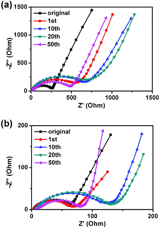 | ||
| Fig. 6 The EIS of H2bhnq (a) and H2bhnq/CMK-3 (b) tested at the potential of 2.3 V and at cycling rate of 0.1 C. | ||
Therefore, the use of CMK-3 is effective to enhance the electrode performance of H2bhnq, which is attributed to the following aspects. Firstly, the high dispersion of H2bhnq in the channels of CMK-3 reduces the dimension of the H2bhnq into the nanoscale and thus provides more active sites for the electrode reactions, enabling the full utilization of the active mass. Secondly, the small channels of CMK-3 greatly restrict the dissolution of the well enwrapped H2bhnq, ensuring the long cycle life of the composite electrode. Thirdly, CMK-3 acts as a substrate offering a sufficient percolation network for electrons and the nanosized H2bhnq shortens the Li-ion transport distance, resulting in a high rate performance. These unique beneficial factors make H2bhnq/CMK-3 a promising nanocomposite to enhance the electrochemical performance. It is noted that the carbon content of 50 wt% is slightly higher than the active materials and this could limit the overall capacity of the electrode. A further optimization of the electrode composition to increase the overall capacity of the electrode is in the study.
Conclusions
A facile impregnation method was employed to incorporate the H2bhnq molecules into the pore channels of ordered mesoporous CMK-3. Different instrumental analyses have demonstrated the successful loading of H2bhnq within the pores of CMK-3. The H2bhnq/CMK-3 nanocomposite with 50 wt% H2bhnq can provide a discharge capacity of 308.6 mAh g−1 at 0.1 C in the first cycle. The capacity was kept at 202.6 mAh g−1 after 50 cycles. At a high rate of 10 C, reversible capacities of 124.0 mAh g−1 are obtained. The results suggest that confining organic electrode materials in inorganic CMK-3 could not only improve the conductivity, but also protect them from dissolving into the electrolyte. This work should enlighten the application of inorganic–organic nanocomposites such as organic carbonyl materials in CMK-3 for advanced lithium-ion batteries.Acknowledgements
This work was supported by the Programs of National 973 (2011CB935900), NSFC (21231005), 111 Project (B12015), and Tianjin High-Tech (13JCQNJC06400).Notes and references
- M. Armand and J. M. Tarascon, Nature, 2008, 451, 652 CrossRef CAS PubMed
.
- J. Chen and F. Cheng, Acc. Chem. Res., 2009, 42, 713 CrossRef CAS PubMed
.
- F. Cheng, J. Liang, Z. Tao and J. Chen, Adv. Mater., 2011, 23, 1695 CrossRef CAS PubMed
.
- H. Chen, M. Armand, M. Courty, M. Jiang, C. P. Grey, F. Dolhem, J. M. Tarascon and P. Poizot, J. Am. Chem. Soc., 2009, 131, 8984 CrossRef CAS PubMed
.
- M. Armand, S. Grugeon, H. Vezin, S. Laruelle, P. Ribière, P. Poizot and J. M. Tarascon, Nat. Mater., 2009, 8, 120 CrossRef CAS PubMed
.
- Y. Liang, Z. Tao and J. Chen, Adv. Energy Mater., 2012, 2, 742 CrossRef CAS
.
- P. Poizot and F. Dolhem, Energy Environ. Sci., 2011, 4, 2003 CAS
.
- W. Choi, D. Harada, K. Oyaizu and H. Nishide, J. Am. Chem. Soc., 2011, 133, 19839 CrossRef CAS PubMed
.
- D. Häringer, J. Electrochem. Soc., 1999, 146, 2393 CrossRef PubMed
.
- X. Han, C. Chang, L. Yuan, T. Sun and J. Sun, Adv. Mater., 2007, 19, 1616 CrossRef CAS
.
- Z. Song, H. Zhan and Y. Zhou, Chem. Commun., 2009, 448 RSC
.
- K. Liu, J. Zheng, G. Zhong and Y. Yang, J. Mater. Chem., 2011, 21, 4125 RSC
.
- T. Nokami, T. Matsuo, Y. Inatomi, N. Hojo, T. Tsukagoshi, H. Yoshizawa, A. Shimizu, H. Kuramoto, K. Komae, H. Tsuyama and J. Yoshida, J. Am. Chem. Soc., 2012, 134, 19694 CrossRef CAS PubMed
.
- T. Le Gall, K. H. Reiman, M. C. Grossel and J. R. Owen, J. Power Sources, 2003, 119–121, 316 CrossRef CAS
.
- J. Xiang, C. Chang, M. Li, S. Wu, L. Yuan and J. Sun, Cryst. Growth Des., 2008, 8, 280 CAS
.
- S. Renault, J. Geng, F. Dolhem and P. Poizot, Chem. Commun., 2011, 47, 2414 RSC
.
- R. Zeng, X. Li, Y. Qiu, W. Li, J. Yi, D. Lu, C. Tan and M. Xu, Electrochem. Commun., 2010, 12, 1253 CrossRef CAS PubMed
.
- S. Wang, L. Wang, K. Zhang, Z. Zhu, Z. Tao and J. Chen, Nano Lett., 2013, 13, 4404 CrossRef CAS PubMed
.
- Y. Hanyu and I. Honma, Sci. Rep., 2012, 2, 453 Search PubMed
.
- W. Huang, Z. Zhu, L. Wang, S. Wang, H. Li, Z. Tao, J. Shi, L. Guan and J. Chen, Angew. Chem., Int. Ed., 2013, 52, 9162 CrossRef CAS PubMed
.
- Y. Liang, P. Zhang, S. Yang, Z. Tao and J. Chen, Adv. Energy Mater., 2013, 3, 600 CrossRef CAS
.
- W. Guo, Y. Yin, S. Xin, Y. Guo and L. Wan, Energy Environ. Sci., 2012, 5, 5221 CAS
.
- Z. Song, T. Xu, M. L. Gordin, Y. B. Jiang, I. T. Bae, Q. Xiao, H. Zhan, J. Liu and D. Wang, Nano Lett., 2012, 12, 2205 CrossRef CAS PubMed
.
- Y. Liang, P. Zhang and J. Chen, Chem. Sci., 2013, 4, 1330 RSC
.
- S. Renault, D. Brandell, T. Gustafsson and K. Edström, Chem. Commun., 2013, 49, 1945 RSC
.
- L. Zhao, W. Wang, A. Wang, Z. Yu, S. Chen and Y. Yang, J. Electrochem. Soc., 2011, 158, A991 CrossRef CAS PubMed
.
- Y. Zhai, Y. Dou, D. Zhao, P. F. Fulvio, R. T. Mayes and S. Dai, Adv. Mater., 2011, 23, 4828 CrossRef CAS PubMed
.
- A. Gutowska, L. Li, Y. Shin, C. M. Wang, X. S. Li, J. C. Linehan, R. S. Smith, B. D. Kay, B. Schmid, W. Shaw, M. Gutowski and T. Autrey, Angew. Chem., Int. Ed., 2005, 44, 3578 CrossRef CAS PubMed
.
- X. Ji, K. T. Lee and L. F. Nazar, Nat. Mater., 2009, 8, 500 CrossRef CAS PubMed
.
- S. Jun, S. H. Joo, R. Ryoo, M. Kruk, M. Jaroniec, Z. Liu, T. Ohsuna and O. Terasaki, J. Am. Chem. Soc., 2000, 122, 10712 CrossRef CAS
.
- K. Yamada, H. Tanaka, S. Yagishita, K. Adachi, T. Uemura, S. Kitagawa and S. Kawata, Inorg. Chem., 2006, 45, 4322 CrossRef CAS PubMed
.
- F. L. S. Bustamante, J. M. Metello, F. A. V. de Castro, C. B. Pinheiro, M. D. Pereira and M. Lanznaster, Inorg. Chem., 2013, 52, 1167 CrossRef CAS PubMed
.
- H. Laatsch, Liebigs Ann. Chem., 1983, 1983, 1886 CrossRef
.
- S. Zhu, H. Zhou, M. Hibino, I. Honma and M. Ichihara, Adv. Funct. Mater., 2005, 15, 381 CrossRef CAS
.
- M. Okubo, E. Hosono, J. Kim, M. Enomoto, N. Kojima, T. Kudo, H. Zhou and I. Honma, J. Am. Chem. Soc., 2007, 129, 7444 CrossRef CAS PubMed
.
- M. Okubo, J. Kim, T. Kudo, H. Zhou and I. Honma, J. Phys. Chem. C, 2009, 113, 15337 CAS
.
- K. Zhang, Z. Hu and J. Chen, J. Energy Chem., 2013, 22, 214 CrossRef CAS
.
- F. Cheng, H. Wang, Z. Zhu, Y. Wang, T. Zhang, Z. Tao and J. Chen, Energy Environ. Sci., 2011, 4, 3668 CAS
.
- Z. Zhu, F. Cheng and J. Chen, J. Mater. Chem. A, 2013, 1, 9484 CAS
.
- J. Fan, T. Wang, C. Yu, B. Tu, Z. Jiang and D. Zhao, Adv. Mater., 2004, 16, 1432 CrossRef CAS
.
Footnote |
| † Electronic supplementary information (ESI) available: the synthetic route of H2bhnq, the FT-IR spectrum, 1H and 13C spectra, TG-DSC curves and SEM images. See DOI: 10.1039/c3qi00076a |
| This journal is © the Partner Organisations 2014 |

