Crosslinking of comb-shaped polymer anion exchange membranes via thiol–ene click chemistry†
Liang
Zhu
a,
Tawanda J.
Zimudzi
a,
Nanwen
Li
b,
Jing
Pan
a,
Bencai
Lin
a and
Michael A.
Hickner
*a
aDepartment of Materials Science and Engineering, The Pennsylvania State University, University Park, PA 16802, USA. E-mail: hickner@matse.psu.edu
bState Key Laboratory of Coal Conversion, Institute of Coal Chemistry, Chinese Academy of Sciences, Taiyuan, 030001, China
First published on 15th February 2016
Abstract
To produce anion conductive and durable polymer electrolytes for alkaline fuel cell applications, a series of cross-linked quaternary ammonium functionalized poly(2,6-dimethyl-1,4-phenylene oxide)s with mass-based ion exchange capacities (IEC) ranging from 1.80 to 2.55 mmol g−1 were synthesized via thiol–ene click chemistry. 1H nuclear magnetic resonance (NMR) spectroscopy and Fourier transform infrared spectroscopy (FTIR) were used to confirm the chemical structure of the samples. From small angle X-ray scattering (SAXS), it was found that the cross-linked membranes developed microphase separation between the hydrophilic PPO backbone and the hydrophobic alkyl side chains. The ion conductivity, dimensional stability, and alkaline durability of the cross-linked membranes were evaluated. The hydroxide ion conductivity of the cross-linked samples reached 60 mS cm−1 in liquid water at room temperature. The chemical stabilities of the membranes were evaluated under severe, accelerated aging conditions and degradation was quantified by measuring the ionic conductivity changes during aging. The cross-linked membranes retained their relatively high ion conductivity and good mechanical properties in both 1 M and 4 M NaOH at 80 °C after 500 h. Attenuated total reflection (ATR) spectra were used to study the degradation pathways of the membranes, and it was determined that β-hydrogen (Hofmann) elimination was likely to be the major pathway for degradation in these membranes.
Introduction
Polymer electrolyte fuel cells (PEFCs) are efficient energy conversion devices that generate electric power from energy-dense and abundant fuels. Fuel cell technology, in general, is regarded as a promising solution to resolve the rising energy demands of society while reducing the negative environmental impact associated with traditional sources of carbon-based energy.1–3 The polymer electrolyte membrane, which serves as a medium for both ion transport as well as a separator to isolate the cathode from the anode during the charging/discharging cycles of a fuel cell, plays a crucial role in the performance of the device. An ideal polymer electrolyte membrane for fuel cells should demonstrate high ionic conductivity, limited dimensional swelling, low fuel crossover, good thermal and mechanical stability, and facile incorporation into the membrane-electrode assembly.4,5 Most low-temperature fuel cells are based on proton exchange membranes. Among these acidic membranes, the most common is Nafion®, which is a perfluorosulfonic acid-based polymer from DuPont. Nafion® is the state-of-the-art proton exchange membrane with good mechanical and chemical stability, and high proton conductivity over a modest relative humidity range.6–9However, PEFCs have some significant drawbacks that hinder widespread commercial application, such as expensive, fluorinated membranes and electrodes that require platinum or precious metal-based catalysts. Alkaline membrane fuel cells (AMFCs) with an anion exchange membrane operating at high pH are currently being studied for their potential to employ non-precious metal catalysts in place of platinum.10,11 The advantages of AMFCs over PEFCs include enhancement of electrode kinetic reactions and more options for cathode catalysts such as non-noble transition metals, improving the performance but reducing the cost of the devices.12–17 Extensive efforts have been devoted to enhancing AEMs’ performance and stability as these types of low-temperature polymer-based fuel cell materials are currently lagging the development and performance attributes of PEMs. A variety of AEMs, with main backbone structures ranging from poly(arylene ether sulfone)s,18,19 poly(olefin)s,20,21 poly(styrene)s,22–24 poly(phenylene oxide)s,25,26 poly(phenylene)s,27 and poly(arylene ether)s18,28–31 to radiated-grafted fluorinated polymers,32 have been widely investigated, but no consensus currently exists on the most promising pathways forward to high-performance AEMs.
The performance of AMFCs is extremely dependent on certain key requirements of the polymer membrane materials: high ion conductivity (>100 mS cm−1), dimensional durability, and chemical stability. Higher charge carrier densities in AEMs are required because of the lower mobility of hydroxide ions compared to protons. In order to achieve sufficient ion conductivity for AEM applications, high ion-exchange capacities (IEC) are essential for anion exchange membranes. However, increasing the IEC values is most often accompanied by high water uptake, leading to severe dimensional swelling, or even dissolution.33,34 This trade-off between swelling and ion conductivity creates a need for methods to enhance the dimensional stability of AEMs without compromising the ion conductivity.35 Cross-linking has been reported as an effective method to enhance the dimensional stability of the membrane and to increase the fuel resistance crossover in the preparation of AEMs.35–50 Several methods have been employed to fabricate cross-linked AEMs. One method is cross-linking via quaternization by diamines, such as N,N,N′,N′-tetramethylhexanediamine.50 When halomethylated polymers were quaternized with alkyldiamines, AEMs with enhanced dimensional integrities, alkaline stabilities, and acceptable hydroxide ion conductivities were achieved.37,42,43,47,48,50 However, cross-linking through quaternization results in a significant reduction in the hydroxide ion conductivity due to the introduction of alkyl chains into the ionic domains and reduced water swelling of the material.37,42,43,47,48,50 Another approach is to introduce a cationic monomer into a network structure. For example, Zha et al.51 reported norbornenes with attached ruthenium complex cations to prepare cross-linked AEMs using ring opening metathesis polymerization (ROMP) and dicyclopentadiene (28.6 mS cm−1 in hydroxide form, at 30 °C). Robertson et al.20 developed a new cross-linked AEM using a cyclooctene cross-linker with quaternary ammonium groups, which showed good mechanical strength and high ion conductivities (111 mS cm−1 in hydroxide form, at 50 °C). Previously, PPO and poly(styrene)-based AEMs have been crosslinked using metathesis of pendant side chain double bonds.40,52 While this strategy was effective at producing highly cross-linked materials at room temperature, some residual catalyst could remain in the membranes, which is not ideal for application in fuel cells.40,52 Additionally, in all of these strategies, the cross-linking of the material occurs as the membrane is cast from solution. Therefore, control of the cross-linking reactions can be difficult and an on-demand cross-linking strategy, as shown in this work using UV light, may be desirable.
In our previous report, we designed comb-shaped polymers based on poly(2,6-dimethyl-1,4-phenylene oxide) backbones with different lengths of pendant alkyl side chains.53 These kinds of polymers showed good ion conductivity under alkaline conditions.53,54 However, due to the increase of the ion exchange capacity (IEC), we were unable to obtain membranes with a degree of functionalization (DF) greater than 70 (70 mol% of the polymer repeat units functionalized) in the pursuit of high-conductivity materials. In order to further enhance the ion conductivity, increase the dimensional stability, and decrease fuel crossover (such as methanol) in the preparation of new AEMs, we herein employ a covalent cross-linking strategy to stabilize comb-shaped AEMs via thiol–ene cross-linking. We introduced side chains with double bonds and used dithiols under UV illumination to accomplish the cross-linking reaction. The advantages of using the thiol–ene click reaction as a strategy for cross-linking are its robustness and efficiency without yielding any harmful byproducts or residue that must be removed from the membrane after the cross-linking reaction has occurred.55 Also, UV-initiated thiol–ene chemistry was shown to proceed quantitatively with a high degree of specificity within a short time.55 In the thiol–ene cross-linking of AEMs, it was observed that the cross-linked samples exhibited a significantly higher dimensional and alkaline stability than that of the uncross-linked AEMs. The OH− conductivity of X80Y40C6 reached as high as 44 and 200 mS cm−1 at 20 and 80 °C, while the dimensional stability of the sample was maintained and did not significantly swell as the temperature was increased.
Experimental
Materials
Poly(2,6-dimethyl-1,4-phenylene oxide) was purchased from Sigma-Aldrich and dried under vacuum at room temperature overnight. N,N-Dimethylhexylamine, N,N-dimethyldecylamine, N,N-dimethylhexadecylamine, N-bromosuccinimide, 1,8-octanedithiol, and 2,2′-azobis(2-methylpropionitrile) were purchased from Sigma-Aldrich and used as received. The brominated PPO polymers with different degrees of bromination (DB) ranging from 60 to 80% were synthesized according to the reported literature.56Synthesis of N,N-dimethyl-10-undecen-1-amine40
20 mL 11-Bromo-1-undecene was mixed with 200 mL toluene, and 100 mL THF solution (50 wt% N,N-dimethylamine). The resulting mixture was stirred at 60 °C for 2 days. Subsequently, the solution was extracted with satd NaHCO3 soln (3 × 60 mL) and distilled water (3 × 60 mL) sequentially. The resulting organic layer was dried with sodium sulfate, filtered, and concentrated by evaporation of the solvent under vacuum. Finally, the obtained colorless liquid was dried in a vacuum at room temperature overnight with a yield of 87% (mass).Polymer synthesis
Brominated PPO with a DB of 0.6 (1.7 g, 10 mmol) was dissolved in 10 mL of N-methyl-pyrrolidone (NMP). Then, N,N-dimethyl-10-undecen-1-amine (0.6 g, 3.0 mmol) was added slowly. The mixture was stirred for 48 h at room temperature. Subsequently, N,N-dimethylhexylamine (0.46 g, 3.6 mmol) was added, and the mixture was stirred for another 24 h at room temperature. The solution obtained was poured into 200 mL toluene or hexane to precipitate the polymer. The product was filtered and further washed with hexane and toluene several times. A light yellow powder was obtained and dried under vacuum overnight at room temperature. The resulting product was cross-linkable comb-shaped PPO (X60Y30C6, where the X60 denotes a polymer with 60 mol% DB (total number of PPO repeat units brominated), the Y30 stands for the mol% of cross-linkable alkene groups (out of the total DB of 60 mol%) attached to the main chain, and the C6 stands for the length of the alkyl chain) with a yield of 93% (mass) in the bromide form. So, the X60Y30C6 polymer has 30 mol% cross-linking and 30 mol% C6 alkyl amine attachment.Fabrication of membranes
The X60Y30C6 comb-shaped polymer (0.3 g) in the bromide form was dissolved in NMP (5 mL) to form a 5 wt% solution. Subsequently, 1,8-octanedithiol (45 mg, 0.24 mmol) was added to the polymer solution. The mixture was stirred for several minutes at room temperature. Then, 2-benzyl-2-(dimethylamino)-4′-morpholinobutyrophenone (photoinitiator, 30 mg) was added to the mixture. The solution was then cast onto a leveled glass plate and exposed to UV light (365 nm) for 10 min. The solution was dried at 82 °C under ambient pressure for 24 h followed by vacuum drying for another 24 h at 80 °C to give a thick, transparent, tough film.Characterization
1H nuclear magnetic resonance (NMR) spectra were recorded at 300 MHz on a Bruker AV 300 spectrometer and chemical shifts were listed in parts per million (ppm) downfield from tetramethylsilane (TMS).The ionic conductivity (σ) was measured using impedance spectroscopy on a Solartron 1260A impedance/gain phase analyzer with a two-point, in-plane geometry at frequencies ranging from 1 MHz to 100 MHz.57 The membrane resistance was obtained from the real value of the impedance where the imaginary response was zero. The σ (mS cm−1) of each membrane sample was calculated from σ = L/RA, where L is the distance between the reference electrodes, R is the resistance of the membrane sample, and A is the cross-sectional area of the sample. Chloride conductivities were measured by exchanging the bromide form membranes in 1 M sodium chloride at room temperature for 24 h followed by extensively rinsing to remove excess salt with degassed and deionized water. Bicarbonate conductivities were measured by exchanging the chloride form membranes in 1 M sodium bicarbonate for 24 h followed by rinsing to remove excess salt. Hydroxide conductivities were measured by exchanging the bicarbonate form membranes in 1 M potassium hydroxide for 24 h followed by rinsing to remove excess salt. The membranes were subsequently placed into conductivity cells and immersed in deionized water that was degassed and blanketed with flowing argon gas.
The density of the membranes in the hydroxide form was measured by a buoyancy method.58 Water uptake was measured after drying the membrane in the corresponding counterion form at 60 °C under vacuum for 24 h. The dried membrane was immersed in water and periodically weighed on an analytical balance until a constant mass was obtained, giving the mass-based water uptake. The water uptake was calculated by (WU = (mhyd − m0)/m0), where mhyd is the hydrated sample mass and m0 is the dry sample mass. The hydration number (λ), or the number of water molecules per ionic group, was calculated from:
 | (1) |
 | (2) |
The swelling degree (SW) was characterized by the linear expansion ratio, which was determined using the difference between wet and dry dimensions of a membrane sample (3 cm in length and 1 cm in width). The calculation was based on the following equation:
 | (3) |
For the cross-linked membranes, the diffusion coefficients of the mobile ions were calculated from a form of the Nernst–Einstein equation:
 | (4) |
 | (5) |
The dilute ion diffusivity can be calculated from the dilute solution mobilities of the mobile ion using the following equation:
 | (6) |
The membranes in the bromide form were immersed in 100 mL of 0.1 M NaNO3 standard solution for 24 h. The solutions were then titrated with a standardized AgNO3 solution using K2CrO3 as an indicator to obtain the experimental weight-based IEC values (IECw).
After cross-linking, the membranes remained insoluble in all common solvents and the gel fraction was used to obtain information on the completeness of the cross-linking reaction. The gel fraction of the cross-linked membranes was calculated from the ratio of the weight of the polymer after extraction with NMP at 80 °C for 1 day and the initial weight of the sample.
FTIR spectra were obtained using a Bruker Vertex 70 FTIR spectrometer (Bruker, Billerica, MA) equipped with a deuterated triglyceride sulphate (DTGS) detector. ATR measurements were carried out on membranes on a MVP-Pro ATR accessory (Harrick Scientific Products, Inc. NY) with a diamond ATR crystal at a 45° incidence angle. Transmission spectra were collected on KBr pellets prepared by mixing 2.5 mg of the polymer with 60 mg of anhydrous KBr (Sigma-Aldrich). The spectra were signal averaged over 100 scans at 4 cm−1 resolution with a 5 mm aperture size and a nitrogen purge at ambient temperature. All spectra were processed using Bruker OPUS 6.5 software.
Small-angle X-ray scattering curves of unstained dry counterion form membranes were obtained using a Rigaku instrument equipped with a pinhole camera with an Osmic microfocus Cu Kα source and a parallel beam optic. Typical counting times for integration over a multiwire area detector were 1 h with typical membrane thicknesses around 100 μm. Measurements were performed under vacuum at ambient temperature on dry samples. Scattering intensities were normalized for background scattering and beam transmission.
Results and discussion
N,N-Dimethyl-10-undecen-1-amine and comb-shaped copolymer synthesis
The cross-linking reagent N,N-dimethyl-10-undecen-1-amine was successfully synthesized from 11-bromo-1-undecene and N,N-dimethylamine according to a previous procedure.40 The chemical structure of this unsaturated dimethyl alkyl amine was confirmed by 1H NMR spectroscopy and is shown in the ESI (Fig. S1†). Br-PPOs possessing different degrees of bromination (DB) at the benzyl position were synthesized using N-bromosuccinimide and 2,2′-azobis(2-methylpropionitrile) in a refluxing chlorobenzene solution for 3 h according to our previous reports.40 By altering the usage of N-bromosuccinimide and 2,2′-azobis(2-methylpropionitrile), Br-PPOs with DB ranging from 60 to 80 were prepared. Then, a series of cross-linkable comb-shaped ionomers (XxYyCz) with different side chain lengths, were achieved by the Menshutkin reaction of the olefinic amine with the bromo group of Br-PPO as shown in Scheme 1 (where the x stands for DB of PPO; y refers to the mol% of cross-linkable alkene groups, and z indicates the side-chain length). The DB of Br-PPO was set at 60 and 80 to obtain samples with calculated IECws ranging from 1.80 to 2.55 mmol g−1 (Table 1). The chemical structures of cross-linkable comb-shaped X80YyC6 cationic copolymers in the bromide form were confirmed by 1H NMR spectroscopy. As shown in Fig. S1,† the disappearance of the proton resonance arising from the bromobenzyl moiety as a sharp peak at 4.3 ppm along with the appearance of new peaks at 0.5–1.8 ppm and 3.0 ppm assigned to alkyl chains indicated that the quaternary ammonium groups were formed. The appearance of peaks 5 and 6 in Fig. S1† indicates the presence of terminal alkene groups in the copolymers. Also, the intensity of peaks 5 and 6 increased as the number of cross-linkable alkene groups was increased. The integral ratio of alkene protons, H5 and H6 at 5.8, 5.1 ppm to aromatic peaks at 6.6–7.1 ppm indicated that the quaternization reaction was quantitative. Likely, due to the deshielding effect of the quaternary ammonium group, a broad resonance from 4.3 to 4.5 ppm was detected, which could be assigned to the benzylic protons (H11 and H12 in Fig. S1†).53 The integral ratio of benzylic protons (H11 and H12 in Fig. S1†) at 4.3 to 4.5 ppm to the aromatic peaks at 6.6–7.1 ppm indicated that the quaternization reaction was quantitative. The IECws of the cross-linkable comb-shaped X80YyC6 membranes calculated from the integral ratios were consistent with the theoretical values, further suggesting the complete and reliable quaternization of the bromomethyl groups.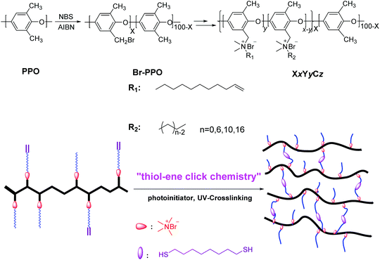 | ||
| Scheme 1 Synthesis of cross-linked comb-shaped AEMs, XxYyCz, with one alkyl side chain using thiol–ene click chemistry. | ||
| Sample | IECa (mmol g−1) | IECb (mmol g−1) | WU (%) (OH−)c | WU (%) (HCO3−)c | WU (%) (Cl−)c | σ (OH−)c | σ (HCO3−)c | σ (Cl−)c | λ (OH−) | Swelling ratiod (%) | Gel fraction (%) |
|---|---|---|---|---|---|---|---|---|---|---|---|
| a Calculated from the polymer composition and the degree of bromination. b Titrated values. c Measured at room temperature in liquid water. d The membranes in the OH− form were used for measurements of the swelling ratio at room temperature in water. | |||||||||||
| X60Y15C6 | 2.51 | 2.25 | 90 ± 6 | 47 ± 3 | 31 ± 2 | 33 ± 3 | 5.3 ± 0.3 | 8.9 ± 0.4 | 22.4 | 23.3 ± 1.4 | 83 |
| X60Y30C6 | 2.38 | 2.06 | 67 ± 5 | 41 ± 2 | 22 ± 2 | 26 ± 3 | 4.2 ± 0.2 | 6.7 ± 0.5 | 18.2 | 15.2 ± 0.9 | 87 |
| X60Y60 | 2.10 | 1.83 | 43 ± 4 | 34 ± 2 | 15 ± 3 | 22 ± 2 | 3.2 ± 0.2 | 4.2 ± 0.2 | 13.5 | 10.6 ± 0.7 | 89 |
| X60Y30C10 | 2.26 | 2.03 | 58 ± 5 | 39 ± 3 | 21 ± 2 | 22 ± 2 | 4.1 ± 0.2 | 5.4 ± 0.3 | 16.6 | 14.5 ± 0.7 | 89 |
| X60Y30C16 | 2.07 | 1.80 | 46 ± 2 | 33 ± 2 | 18 ± 2 | 17 ± 1 | 3.3 ± 0.2 | 4.9 ± 0.2 | 14.2 | 13.2 ± 0.8 | 90 |
| X80Y20C6 | 2.94 | 2.55 | 193 ± 4 | 56 ± 3 | 43 ± 4 | 60 ± 5 | 12.2 ± 1.1 | 14.9 ± 1.2 | 42.5 | 40.7 ± 3.3 | 87 |
| X80Y40C6 | 2.63 | 2.35 | 144 ± 4 | 43 ± 3 | 30 ± 3 | 44 ± 2 | 8.4 ± 0.7 | 10.9 ± 0.5 | 34.9 | 25.0 ± 2.0 | 92 |
| X80Y80 | 2.39 | 2.17 | 76 ± 3 | 24 ± 3 | 13 ± 2 | 23 ± 3 | 3.8 ± 0.3 | 5.8 ± 0.3 | 21.8 | 13.3 ± 0.8 | 95 |
| X80Y40C10 | 2.52 | 2.20 | 49 ± 3 | 31 ± 3 | 20 ± 1 | 21 ± 3 | 5.1 ± 0.3 | 7.6 ± 0.4 | 12.7 | 15.4 ± 1.1 | 95 |
| X80Y40C16 | 2.41 | 2.08 | 26 ± 1 | 20 ± 2 | 12 ± 1 | 18 ± 2 | 3.4 ± 0.2 | 4.8 ± 0.3 | 7.3 | 9.5 ± 0.6 | 96 |
As 1,8-octanedithiol and the photoinitiator showed good solubility in NMP which is also a good solvent for the precursor polymer, all the components of the membrane casting solution were well-distributed to form a homogeneous solution. The homogeneous solution was cast on a leveled glass plate and exposed to UV light for 10 min before being placed in a convection oven at 80 °C overnight. Ductile, light brown, tough and transparent membranes with a thickness of approximately 70 μm were obtained. The obtained membranes exhibited excellent resistance to polar solvents such as methanol and ethanol indicating high levels of cross-linking. The IECw values were measured by titration in the range of 1.80 to 2.55 mmol g−1, which were in good agreement with the values calculated from the 1H NMR analysis.
FTIR was used to confirm the reaction of the alkene double bonds with the thiols to form the cross-linked network. As shown in Fig. 1, there was a distinct ν(C![[double bond, length as m-dash]](https://www.rsc.org/images/entities/char_e001.gif) C) peak at 1639 cm−1 for the uncross-linked X60Y60 membrane, which disappeared after cross-linking along with the ν(
C) peak at 1639 cm−1 for the uncross-linked X60Y60 membrane, which disappeared after cross-linking along with the ν(![[double bond, length as m-dash]](https://www.rsc.org/images/entities/char_e001.gif) C–H) peak at 909 cm−1.64 Considering all the evidence, a strong covalent cross-linked network was formed by the thiol–ene click cross-linking reaction which was further confirmed by the gel fraction (>80%) in NMP, Table 1. In order to test the reliability and stability of the UV-initiated thiol–ene cross-linking method, each experimental condition was repeated three times to prepare three membrane samples, suggesting that UV cross-linking is a viable strategy for cross-linking these copolymers.
C–H) peak at 909 cm−1.64 Considering all the evidence, a strong covalent cross-linked network was formed by the thiol–ene click cross-linking reaction which was further confirmed by the gel fraction (>80%) in NMP, Table 1. In order to test the reliability and stability of the UV-initiated thiol–ene cross-linking method, each experimental condition was repeated three times to prepare three membrane samples, suggesting that UV cross-linking is a viable strategy for cross-linking these copolymers.
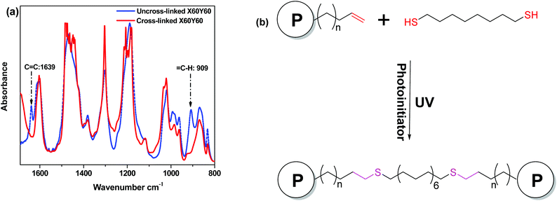 | ||
| Fig. 1 FTIR spectra of uncross-linked and cross-linking membranes (a) and schematic plot of the cross-linking reaction (b). | ||
Swelling behavior
To demonstrate the effect of the degree of cross-linking (DC) on the swelling behavior of the AEM samples, we compared the water uptakes and swelling ratios of X60YyC6 and X80YyC6 membranes with different degrees of cross-linking (DCs). As shown in Fig. 2, the thiol–ene cross-linking drastically lowered the water uptake and thus the swelling ratio of the AEMs. Specifically, the cross-linked X80Y40C6 membrane had a water uptake of 144% and swelling ratio of 25% at room temperature while the uncross-linked X80Y0C6 sample could be dissolved in water. In addition, the water uptake and swelling ratio of the samples generally decreased with increasing DCs. For example, X60Y15C6 and X60Y60 water uptakes were 90 wt% and 43 wt%, and the swelling ratios were 23% and 10% at room temperature, respectively. In contrast, uncross-linked X60Y0C6 showed a greater water uptake (173 wt%) and swelling ratio (60 wt%) compared to either of the cross-linked samples. | ||
| Fig. 2 Liquid water uptake (a) and swelling ratio (b) of membranes in the OH− form as a function of degree of cross-linking at room temperature. | ||
Fig. 3 compares the swelling behaviors at elevated temperatures of membranes with different DCs. Although the water uptakes and swelling ratios for all the samples increased with elevated temperatures, increasing the DCs significantly enhanced the dimensional stability of the AEMs. For X60Y30C6 and X80Y40C6, the water uptakes were 67 wt% and 144 wt%, and the swelling ratios were 15% and 25% at room temperature, respectively. When the temperature was increased to 80 °C, the water uptake of the samples increased to 93 wt% and 173 wt%, and their swelling ratios went up to 35% and 48%, respectively. In comparison, large increases of the water uptake and swelling ratio were observed for the uncross-linked X60Y0C6 sample when the temperature was increased from 20 to 80 °C (increases of 157% for water uptake increment and 130% for swelling ratio increment). Considering the remarkable agreement between the high solvent resistance and low swelling ratio, a strong covalent cross-linking network was likely formed by the thiol–ene cross-linking. In addition, it is shown in Fig. S2† that a longer alkyl side chain restricted the water absorption of AEMs, resulting in lower ion conductivity.53
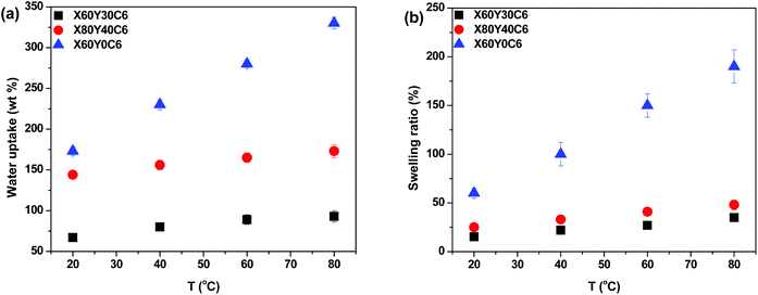 | ||
| Fig. 3 Liquid water uptake (a) and swelling ratio (b) of membranes in the OH− form as a function of temperature. | ||
Ionic conductivity
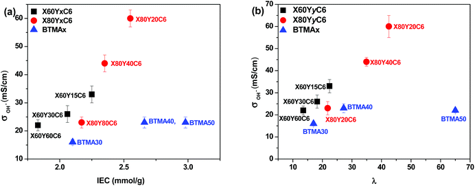
High ionic conductivity is one of the most important properties for the application of AEMs in devices. As shown in Fig. 4a, the hydroxide conductivity of the cross-linked membranes increased with increasing IEC because of the increase in the water content. When comparing the hydroxide conductivity of the cross-linked and BTMA (benzyltrimethyl ammonium) membranes, the cross-linked membranes demonstrated much higher hydroxide conductivity under the same conditions. For example, the X80Y20C6 membrane with IEC = 2.65 mmol g−1 showed a conductivity of 60 mS cm−1, which was almost three times greater than that of the BTMA40 membrane (23 mS cm−1) with an IEC of 2.66 mmol g−1. It should also be pointed out that the cross-linked membranes showed much larger hydroxide conductivity than the BTMAx membranes for a given hydration number (λ), Fig. 4b.The hydroxide conductivity of the X60YxC6 and BTMA30 membranes as a function of temperature along with the water uptake of the samples is shown in Fig. 5. The hydroxide conductivity steadily increased with increasing temperature and displayed values of 89–200 mS cm−1 for X80YxC6 membranes at 80 °C, which are greater than the previously reported values for high conductivity AEMs.18,21,35–44 For example, Gu et al.30 reported SCL-TPQPOH with an IEC = 1.23 mmol g−1 exhibiting a hydroxide conductivity of 32.7 mS cm−1 in water at room temperature. The cross-linked PP-AEMs synthesized by Zhang et al.37 exhibited a hydroxide conductivity of 56.5 mS cm−1 in deionized water at 80 °C. The cross-linked, epoxy-based AEMs reported by Zhou et al.44 exhibited a hydroxide conductivity of 14 mS cm−1 and 78 mS cm−1 at 30 and 80 °C, respectively. Yang et al.65 synthesized poly(2,6-dimethyl-1,4-phenylene oxide)-b-poly(vinylbenzyltrimethylammonium) diblock copolymer-based AEMs by growing poly(vinylbenzyl chloride) (PVBC) blocks from a PPO macroinitiator using nitroxide-mediated polymerization. These AEMs exhibited a hydroxide conductivity as high as 132 mS cm−1 in deionized water at 60 °C with IEC = 2.9 mmol g−1. The X80Y40C6 sample exhibited the highest OH− conductivity (200 mS cm−1) at 80 °C, which was nearly six times higher than that of BTMA30 under the same conditions. The X80Y40C6 membranes exhibited the highest hydroxide conductivity above 40 °C due to a trade-off between the water uptake, ionic content and conductivity and did not swell greatly like the X80Y20C6 membranes with less crosslinking that showed promising conductivity at lower temperatures. As shown in Fig. S3,† the HCO3− conductivities of the membranes showed an approximate Arrhenius-type temperature dependence promoted by the thermal activation of water motion.66 The apparent activation energy estimated from the slopes of the ln(σ) vs. 1000/T curves was ∼12.2–22.5 kJ mol−1 across the measured samples. The apparent activation energies of the tested membranes were comparable to or somewhat lower than those of the other reported AEMs (10–23 kJ mol−1), indicating that these membranes have a water-facilitated OH− conduction mechanism similar to other hydrated AEMs.66
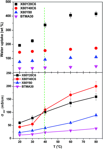 | ||
| Fig. 5 Hydroxide conductivity of X80YxC6 and BTMA30 membranes as a function of temperature. Conductivities were measured with samples exposed to liquid water. | ||
After normalizing the samples’ hydroxide conductivity on the basis of water volume fraction, the effective hydroxide conductivity in the water channels, σ′, which demonstrates the efficiency of the water molecules inside the membranes for the transport of hydroxide ions, was obtained.53 All of the cross-linked membranes showed a higher σ′ than the corresponding BTMAx samples, as shown in Fig. S4.† These results indicated that the well-developed micro-phase separation of the cross-linked samples, as discussed in the next section, could efficiently enhance the transport of hydroxide ions.
Morphological characterization
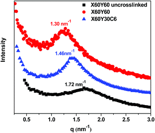
More efficient ion transport in anion exchange membranes usually results from better-developed OH− transport pathways as the material is hydrated. Generally, for the different AEMs with similar IECs and water uptakes, it is desirable to promote ionic domain aggregation, which ensures ionic channels for good transport. To investigate the microphase separated morphologies of the materials in this study, small-angle X-ray scattering (SAXS) was used to investigate the X60Y60, X60Y30C6, and uncross-linked X60Y60 samples. SAXS profiles, Fig. 6, reveal clear scattering peaks for all samples. These results were indicative of nanophase separation between the polar PPO backbone with attached ionic groups and the hydrophobic alkyl side chains. The lack of a second order scattering peak for all the cross-linked membranes demonstrated that no long range ordered structures were formed in these membranes, but only locally correlated arrangement of phase separated domains existed. Generally, the characteristic separation length or interdomain spacing, d, between the ion-rich domains in ionomers can be calculated by the values of qmax through the equation d = 2π/qmax. The corresponding interdomain spacing values fall in the range of 3.6–4.8 nm, which roughly corresponds to double the length of the extended aliphatic side chains.53 As shown in Fig. 6, the ionic domain peak of the highly cross-linked membrane X60Y60 shifted to a lower q value (higher d value) upon cross-linking, likely indicating extension of the ionic domains with the addition of the cross-linking reagent.In our previous report,67 we developed a method for analyzing the mobility of ions in PEMs and AEMs via calculating the ion diffusion coefficients (D) which included information obtained from conductivity, ion concentration, and water uptake of the polymer membranes. For different ions, we calculated the barrier to ion transport via the ratio of the diffusion coefficient to the dilute ion diffusivity (D/D0), where D0 is the maximum diffusivity of an ion in water.68 As shown in Fig. 7, the D/D0 ratio increased with increasing hydration for membranes in the hydroxide form, the highest D/D0 ratio obtained was 0.79 at λ = 43 with IEC = 2.41 meq g−1 for the X80Y20C6 sample. The cross-linked membranes showed relatively higher D/D0 values than the BTMA membranes at the same λ, suggesting more facile transport of hydroxide in the phase-separated systems as demonstrated by SAXS.
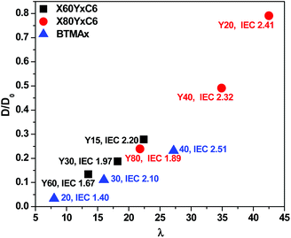 | ||
| Fig. 7 Ratio of the diffusion coefficient, D, to the dilute solution diffusivity, D0, as a function of hydration number for membranes in the hydroxide form. | ||
Membrane stability
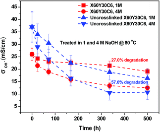
The long-term stability of AEMs is generally of concern due to the known degradation pathways for tetraalkylammonium ions under alkaline conditions, such as β-hydrogen (Hofmann) elimination, direct nucleophilic substitution at the α-carbon, and benzyl attack.69–73 The possible degradation mechanism of these membranes is shown in Scheme 2. The products of the different degradation pathways may help to unravel the most prominent degradation mechanisms of the materials. For example, the formation of an alkene accompanies Hofmann elimination while debenzylation results in the appearance of benzyl alcohol. While the signatures of degradation (such as the formation of a tertiary amine during debenzylation and demethylation) maybe convoluted, careful examination of the degradation byproducts will lead to better understanding of the most vulnerable sites for hydroxide attack on these materials and provides a basis for improvement of next-generation membranes.To evaluate the long-term alkaline stability of the AEMs, the X60Y30C6 and uncross-linked X60Y30C6 samples were immersed in argon-saturated 1 M NaOH solution at 80 °C for 500 hours, with the replacement of 1 M NaOH every 3 days during the testing period. Fig. 8 illustrates the changes in the OH− conductivity during the stability testing of the samples. During the 500 h test, X60Y30C6 exhibited significantly greater cation stability than that of uncross-linked X60Y30C6. The OH− conductivity of X60Y30C6 decreased by 27.0% and 52.0%, in 1 M and 4 M NaOH solutions, respectively. In contrast, the OH− conductivity of the uncross-linked X60Y30C6 film decreased by 57.0% and 73.1%, in 1 M and 4 M NaOH solutions, respectively. The better stability of the cross-linked AEMs was demonstrated due to the cross-linking of alkyl side chains.44
In order to further study the degradation pathways and mechanisms, ATR-FTIR spectroscopy was employed to characterize the membranes after being treated in 1 M sodium hydroxide at 80 °C. As stated previously, in the AEMs, the major degradation pathways are benzyl attack, direct nucleophilic substitution at the α-carbon, or β-hydrogen (Hofmann) elimination.69–73 Analysis of the ATR spectra of membranes after degradation in base provided a method to differentiate between the three mechanisms. Notably, the intensity of the ν(CH2) peak of the long alkyl side chains at 2915–2945 and 2840 cm−1 decreased as the degradation time increased which is shown in Fig. 9a, indicating that β-hydrogen (Hofmann) elimination and/or benzyl attack occurred during the testing period.74 The characteristic benzyl alcohol peaks between 3625 cm−1 and 3180 cm−1 were not readily evident in the spectra, indicating that benzyl attack may be a minor pathway in solid membranes, while β-hydrogen (Hofmann) elimination is a major pathway for degradation. In addition, the new peaks in Fig. 9a, assigned to ν(CH) of (NCH3)2CH2 appeared at 2975, 2820 and 2770 cm−1, demonstrating the formation of the NC3 group.75 This observation further confirmed that β-hydrogen (Hofmann) elimination could be the major pathway for degradation in membranes. As shown in Fig. 9b, two new peaks assigned to ν(NC3) at 735 and 1035 cm−1 became apparent in the fingerprint region for the degraded membranes.75 In addition, another new peak assigned to ν(CH2) of –CH2–NC3 appeared at 1236 cm−1 supporting the formation of the NC3 group.75 The intensity of the peak assigned to ν(CH3) of N+(CH3)3 at 1383 cm−1 weakened as the degradation time increased.76,77 All the degradation information in the ATR-FTIR spectra demonstrated that β-hydrogen (Hofmann) elimination was a major pathway for degradation in these membranes.
 | ||
| Fig. 9 ATR spectra of the treated X60Y15C6 membrane. (a) ATR spectra of the functional group region and (b) fingerprint region. | ||
Conclusions
In summary, we have designed and synthesized a new class of cross-linkable, comb-shaped copolymers for stable anion exchange membrane applications. The cross-linked comb-shaped membranes were achieved by thiol–ene click chemistry and the degree of cross-linking was readily controlled by tuning the amount of alkene-containing side chains pendant to the polymer backbone. The obtained cross-linked AEMs displayed a nanoscale phase-separated morphology, which was responsible for the higher ion conductivity of these materials compared to conventional BTMA AEMs. The cross-linking of the membranes enhanced both the chemical and dimensional stabilities of the membranes. After 500 h immersion in 1 M and 4 M NaOH at 80 °C, the cross-linked membranes maintained a significantly higher hydroxide conductivity than those of the uncross-linked AEMs. The ATR-FTIR spectra clearly demonstrated that the major degradation pathway of the quaternary ammonium functionalized poly(2,6-dimethyl-1,4-phenylene oxide)s under alkaline conditions was β-hydrogen (Hofmann) elimination. The combination of the good solubility of the precursor and the highly efficient thiol–ene click chemistry enables this cross-linking strategy as a promising technology for preparing attractive AEM materials for fuel cell applications.Acknowledgements
This work was funded by the Advanced Research Projects Agency – Energy (ARPA-E), U.S. Department of Energy, under award number: DE-AR0000121 and the United States-Israel Binational Science Foundation (BSF) through Energy Project no. 2011521.References
- A. J. Appleby and F. R. Foulkes, Fuel Cell Handbook, Van Nostrand Reinhold, New York, 1989 Search PubMed.
- L. Carratte, K. A. Friedlich and U. Stimming, Fuel Cells, 2001, 1, 5–39 CrossRef.
- B. C. H. Steele and A. Heinzel, Nature, 2001, 414, 345–352 CrossRef CAS PubMed.
- G. Merle, M. Wessling and K. Nijmeijer, J. Membr. Sci., 2011, 377, 1–35 CrossRef CAS.
- J. J. Fontanella, M. G. McLin, M. C. Wintersgill, J. P. Calame and S. G. Greenbaum, Solid State Ionics, 1993, 66, 1–4 CrossRef CAS.
- C. H. Lee, H. B. Park, Y. M. Lee and R. D. Lee, Ind. Eng. Chem. Res., 2005, 44, 7617–7626 CrossRef CAS.
- R. F. Silva, M. De Francesco and A. Pozio, J. Power Sources, 2004, 134, 18–26 CrossRef CAS.
- A. Filipi, M. Boccia and H. A. Gasteiger, ECS Trans., 2008, 16, 1835–1845 Search PubMed.
- J. R. Vorcoe and R. C. T. Slade, Fuel Cells, 2005, 2, 187–200 CrossRef.
- T. Xu, J. Membr. Sci., 2005, 263, 1–29 CrossRef CAS.
- M. A. Hickner, Mater. Today, 2010, 13, 34–41 CrossRef CAS.
- T. S. Olson, S. Pylypenko, P. Atanassov, K. Asazawa, H. Yamada and H. Tanaka, J. Phys. Chem. C, 2010, 114, 5049–5059 CAS.
- J. Sanabria-Chinchilla, K. Asazawa, T. Sakamoto, K. Yamada, T. Tanaka and P. Strasser, J. Am. Chem. Soc., 2011, 133, 5425–5431 CrossRef CAS PubMed.
- J. Pan, C. Chen, L. Zhuang and J. Lu, Acc. Chem. Res., 2012, 45, 471–483 CrossRef PubMed.
- Y. Wang, J. Qiao, R. Baker and J. Zhang, Chem. Soc. Rev., 2013, 42, 5768–5787 RSC.
- J. R. Varcoe, R. C. T. Slade, G. L. Wright and Y. L. Chen, J. Phys. Chem. B, 2006, 110, 21041–21049 CrossRef CAS PubMed.
- X. Wu and K. Scott, J. Power Sources, 2012, 206, 14–19 CrossRef CAS.
- J. Yan and M. A. Hickner, Macromolecules, 2010, 43, 2349–2356 CrossRef CAS.
- N. Li, Q. Zhang, C. Wang, Y. M. Lee and M. D. Guiver, Macromolecules, 2012, 45, 2411–2419 CrossRef CAS.
- N. J. Robertson, H. A. Kostalik IV, T. J. Clark, P. F. Mutolo, H. D. Abruña and G. W. Coates, J. Am. Chem. Soc., 2010, 132, 3400–3404 CrossRef CAS PubMed.
- K. J. Noonan, K. M. Hugar, H. A. Kostalik IV, E. B. Lobkovsky, H. D. Abruña and G. W. Coates, J. Am. Chem. Soc., 2012, 134, 18161–18164 CrossRef CAS PubMed.
- T. H. Tsai, A. M. Maes, M. A. Vandiver, C. Versek, S. Seifert, M. Tuominen, M. W. Liberatore, A. M. Herring and E. B. Coughlin, J. Polym. Sci., Part B: Polym. Phys., 2012, 51, 1751–1760 CrossRef.
- Q. H. Zeng, Q. L. Liu, I. Broadwell, A. M. Zhu, Y. Xiong and X. P. Tu, J. Membr. Sci., 2010, 349, 237–243 CrossRef CAS.
- Y. Luo, J. Guo, C. Wang and D. Chu, J. Power Sources, 2010, 195, 3765–3771 CrossRef CAS.
- L. Wu, G. Zhou, X. Liu, Z. H. Zhang, C. Li and T. Xu, J. Membr. Sci., 2011, 371, 155–162 CrossRef CAS.
- A. D. Mohanty, Y.-B. Lee, L. Zhu, M. A. Hickner and C. Bae, Macromolecules, 2014, 47, 1973–1980 CrossRef CAS.
- M. R. Hibbs, C. H. Fujimoto and C. J. Cornelius, Macromolecules, 2009, 42, 8316–8321 CrossRef CAS.
- M. R. Hibbs, M. A. Hickner, T. M. Alam, S. K. McIntyre, C. Y. Fujimoto and C. Cornelius, J. Chem. Mater., 2008, 20, 2566–2573 CrossRef CAS.
- J. Wang, S. Li and S. Zhang, Macromolecules, 2010, 43, 3890–3896 CrossRef CAS.
- S. Gu, R. Cai and Y. Yan, Chem. Commun., 2011, 47, 2856–2858 RSC.
- Z. Zhao, J. Wang, S. Li and S. Zhang, J. Power Sources, 2011, 196, 4445–4450 CrossRef CAS.
- J. R. Varcoe, R. C. T. Slade, E. L. H. Yee, S. D. Poynton, D. J. Driscoll and D. C. Apperley, Chem. Mater., 2007, 19, 2686 CrossRef CAS.
- J. R. Varcoe, P. Atanassov, D. R. Dekel, A. M. Herring, M. A. Hickner, P. A. Kohl, A. R. Kucernak, W. E. Mustain, K. Nijmeijer, K. Scott, T. Xu and L. Zhuang, Energy Environ. Sci., 2014, 7, 3135 CAS.
- J. Pan, S. Lu, Y. Li, A. Huang, L. Zhuang and J. Lu, Adv. Funct. Mater., 2009, 19, 1–8 Search PubMed.
- T. H. Tsai, S. P. Ertem, A. M. Maes, S. Seifert, A. M. Herring and E. B. Coughlin, Macromolecules, 2015, 48, 655–662 CrossRef CAS.
- J. Pan, L. Zhu, J. Han and M. A. Hickner, Chem. Mater., 2015, 27, 6689–6698 CrossRef CAS.
- M. Zhang, J. Liu, Y. Wang, L. An, M. D. Guiver and N. Li, J. Mater. Chem. A, 2015, 3, 12284–12296 CAS.
- Y. Z. Zhuo, A. N. Lai, Q. G. Zhang, A. M. Zhu, M. L. Ye and Q. L. Liu, J. Membr. Sci., 2015, 491, 138–148 CrossRef CAS.
- B. Lin, F. Chu, Y. Ren, B. Jia, N. Yuan, H. Shang, T. Feng, Y. Zhu and J. Ding, J. Power Sources, 2014, 266, 186–192 CrossRef CAS.
- N. Li, L. Wang and M. A. Hickner, Chem. Commun., 2014, 50, 4092–4095 RSC.
- B. Lin, H. Dong, Y. Li, Z. Si, F. Gu and F. Yan, Chem. Mater., 2013, 25, 1858–1867 CrossRef CAS.
- X. Lin, Y. Liu, S. D. Poynton, L. Ong, A. J. R. Varcoe, L. Wu, Y. Li, X. Liang, Q. Li and T. Xu, J. Power Sources, 2013, 233, 259–268 CrossRef CAS.
- Y. Zhao, H. Yu, D. Yang, J. Li, Z. Shao and B. Yi, J. Power Sources, 2013, 221, 247–251 CrossRef CAS.
- J. F. Zhou, M. Unlu, I. Anestis-Richard and P. A. Kohl, J. Membr. Sci., 2010, 350, 286–292 CrossRef CAS.
- C. C. Yang, S. J. Chiu, W. C. Chien and S. S. Chiu, J. Power Sources, 2010, 195, 2212–2219 CrossRef CAS.
- B. Lin, L. Qiu, J. Lu and F. Yan, Chem. Mater., 2010, 22, 6718–6725 CrossRef CAS.
- Y. Xiong, J. Fang, Q. H. Zeng and Q. L. Liu, J. Membr. Sci., 2008, 311, 319–325 CrossRef CAS.
- D. Stoica, L. Ogier, L. Akrour, F. Alloin and J. F. Fauvarque, Electrochim. Acta, 2007, 53, 1596–1603 CrossRef CAS.
- Y. H. Wu, C. M. Wu, T. W. Xu, F. Yu and Y. X. Fu, J. Membr. Sci., 2008, 321, 299–308 CrossRef CAS.
- J. S. Park, S. H. Park, S. D. Yim, Y. G. Yoon, W. Y. Lee and C. S. Kim, J. Power Sources, 2008, 178, 620–626 CrossRef CAS.
- Y. Zha, M. L. Disabb-Miller, Z. D. Johnson, M. A. Hickner and G. N. Tew, J. Am. Chem. Soc., 2012, 134, 4493–4496 CrossRef CAS PubMed.
- L. Wang and M. A. Hickner, Polym. Chem., 2014, 5, 2928–2935 RSC.
- N. W. Li, Y. J. Leng, M. A. Hickner and C. Y. Wang, J. Am. Chem. Soc., 2013, 135, 10124–10133 CrossRef CAS PubMed.
- A. Amel, L. Zhu, M. Hickner and Y. Ein-Eli, J. Electrochem. Soc., 2014, 161, F615–F621 CrossRef CAS.
- K. L. Killops, L. M. Campos and C. J. Hawker, J. Am. Chem. Soc., 2008, 130, 5062–5064 CrossRef CAS PubMed.
- N. Li, T. Yan, Z. Li, T. Thurn-Albrecht and W. H. Binder, Energy Environ. Sci., 2012, 5, 7888–7892 CAS.
- C. H. Fujimoto, M. A. Hickner, C. J. Cornelius and D. A. Loy, Macromolecules, 2005, 38, 5010–5016 CrossRef CAS.
- W. Xie, H. Ju, M. G. Geise, B. D. Freeman, J. I. Mardel, A. J. Hill and J. E. McGrath, Macromolecules, 2011, 44, 4428–4438 CrossRef CAS.
- H. J. Walls, P. S. Fedkiw, T. A. Zawodzinski and S. A. Khan, J. Electrochem. Soc., 2003, 150, E165–E174 CrossRef CAS.
- Y. Kim, B. Einsla, M. Sankir, W. Harrison and B. Pivovar, Polymer, 2006, 47, 4026 CrossRef CAS.
- M. Muthukumar, Advances in Chemical Physics, ed. S. A. Rice, 2005, vol. 131, p. 45 Search PubMed.
- D. Voet and J. G. Voet, Biochemistry, John Wiley & Sons, 4th edn, 2011, p. 45 Search PubMed.
- P. Vanysek, CRC Handbook of Chemistry and Physics, ed. D. R. Lide, CRC Press, Boca Raton, 2002 Search PubMed.
- M. Sclavons, M. Laurent, J. Devaux and V. Carlier, Polymer, 2005, 46, 8062–8067 CrossRef CAS.
- Y. Yang and D. M. Knauss, Macromolecules, 2015, 48, 4471–4480 CrossRef CAS.
- D. Chen and M. A. Hickner, Macromolecules, 2013, 46, 9270–9278 CrossRef CAS.
- M. L. Disabb-Miller, Y. Zha, A. J. DeCarlo, M. Pawar, G. N. Tew and M. A. Hickner, Macromolecules, 2013, 46, 9279–9287 CrossRef CAS.
- M. L. Disabb-Miller, Z. D. Johnson and M. A. Hickner, Macromolecules, 2013, 46, 949–956 CrossRef CAS.
- J. R. Varcoe and R. C. T. Slade, Fuel Cells, 2005, 2, 187–200 CrossRef.
- S. A. Nuñez and M. A. Hickner, ACS Macro Lett., 2013, 2, 49–52 CrossRef.
- S. Chempath, B. R. Einsla, L. R. Pratt, C. S. Macomber, J. M. Boncella, J. A. Rau and B. S. Pivovar, J. Phys. Chem. C, 2008, 112, 3179–3182 CAS.
- B. R. Einsla, S. Chempath, L. R. Pratt, J. M. Boncella, J. Rau, C. Macomber and B. S. Pivovar, ECS Trans., 2007, 11, 1173–1180 CAS.
- C. S. Macomber, J. M. Boncella, B. S. Pivovar and J. A. Rau, J. Therm. Anal. Calorim., 2008, 93, 225–229 CrossRef CAS.
- W. Zhou, N. Yao, G. Yao, C. Deng, X. Zhang and P. Yang, Chem. Commun., 2008, 5577–5579 RSC.
- J. N. Gayles, Spectrochim. Acta, Part A, 1967, 23, 1521–1531 CrossRef CAS.
- K. O. Christe, W. W. Wilson, R. D. Wilson, R. Bau and J. A. Feng, J. Am. Chem. Soc., 1990, 112, 7619–7625 CrossRef CAS.
- E. A. V. Ebsworth and N. Sheppard, Spectrochim. Acta, 1959, 13, 261–270 CrossRef CAS.
Footnote |
| † Electronic supplementary information (ESI) available. See DOI: 10.1039/c5py01911g |
| This journal is © The Royal Society of Chemistry 2016 |

