 Open Access Article
Fiber-reinforced quasi-solid polymer electrolytes enabling stable Li-metal batteries†
Shilun
Gao‡
a,
Youjia
Zhang‡
a,
Mengxiang
Ma
a,
Zhenxi
Li
a,
Zongxue
Sun
b,
Ming
Tian
 b,
Huabin
Yang
*ac and
Peng-Fei
Cao
 *b
*b
aInstitute of New Energy Material Chemistry, School of Materials Science and Engineering, Nankai University, Tianjin 300350, China. E-mail: hb_yang@nankai.edu.cn
bState Key Laboratory of Organic-Inorganic Composites, Beijing University of Chemical Technology, Beijing 100029, China. E-mail: caopf@buct.edu.cn
cTianjin Key Laboratory of Metal and Molecular Based Material Chemistry, School of Materials Science and Engineering, Nankai University, Tianjin 300350, China
First published on 16th May 2023
Abstract
With high ionic conductivity and good contact/adhesion with electrodes, quasi-solid polymer electrolytes (QPEs) are considered as one of the most promising options to address the safety concerns of next-generation rechargeable batteries. A trade-off exists between mechanical strength and ionic conductivity, e.g., a high electrolyte uptake ratio leads to high ionic conductivity while low mechanical strength, and vice versa. Constructing QPEs with integrated high ionic conductivity and mechanical robustness is crucial in promoting the practical use of safe and long-cycling lithium (Li)-metal batteries (LMBs). Herein, by integrating the poly(propylene) fiber (PPF) and a rationally designed polymer network, i.e., poly[poly(ethylene glycol) methyl ether methacrylate)-r-(2-ethylhexyl acrylate)-r-sodium (p-styrene sulfonate)-r-polyethylene glycol dimethacrylate] (PPES), a mechanically reinforced PPES@PPF film is obtained with a decent Young's modulus of ∼190 MPa. This fiber reinforced QPE (rQPE) exhibits a high ionic conductivity of 1.1 mS cm−1 at 60 °C. The resulting Li/rQPE/LiFePO4 (LFP) cell shows excellent cycling stability with a capacity retention of 91% over 900 cycles. Moreover, a cell with ultra-thin QPE (tQPE, ∼10 µm) and a high-voltage LiNi0.8Mn0.1Co0.1O2 (NMC811) cathode was also assembled, and delivers stable cycling performance over 300 cycles with a capacity retention of 80%. The current design of fiber-reinforced QPE not only surpasses the mechanical strength–ionic conductivity trade-off of QPEs, but also sheds light on the application of solid electrolytes for high-energy density LMBs.
1. Introduction
With the ever-increasing demand for high-energy density energy storage devices including small portable electronics and large-scale energy storage devices, the state-of-the-art lithium ion batteries (LIBs) based on the graphite anode cannot meet future applications, triggering huge research attention in the exploration of alternative electrode candidates.1–5 Metallic Li with ultrahigh theoretical specific capacity (3860 mA h g−1) and the lowest electrochemical potential (−3.040 V vs. standard hydrogen electrode) is regarded as an ideal anode material for high-energy density rechargeable batteries.6–10 Unfortunately, three drawbacks severely impede the application of liquid electrolytes in Li-metal batteries (LMBs): (1) Arising from the non-uniform Li deposition, the uncontrollable growth of Li dendrites can even penetrate the separator, leading to short-circuits (or micro short-circuits) of the batteries.11,12 (2) Due to the high reactivity of metallic Li, the side reactions between the Li electrode and liquid electrolyte result in the formation of an intrinsic solid electrolyte interphase (SEI) layer, which is mechanically brittle and cannot accommodate the volume variation of the Li electrode.13–16 The repeated formation/destruction of this intrinsic SEI layer will continuously consume the electrolyte and Li electrode, rendering low coulombic efficiency (CE) and poor cycling stability. (3) The Li electrode in an organic liquid electrolyte also leads to serious safety issues, such as electrolyte leakage, gas formation and even explosion.17–20Solid electrolytes, including inorganic solid electrolytes and solid polymer electrolytes, have been considered as more promising candidates to inhibit the Li dendrite growth and address the safety issues of LMBs.21–25 Generally, an ideal solid electrolyte should possess high ionic conductivity, good mechanical strength, and an intimate electrode/electrolyte interface.26–28 Nevertheless, the low ionic conductivity (much lower than that of a liquid electrolyte) and poor electrode/electrolyte contact severely impede their practical applications.29,30 Comparatively, by eliminating the leaking risk of liquid electrolytes while retaining intimate interfacial contact, the quasi-solid polymer electrolyte (QPE) shows great advantages in high safety and low electrolyte/electrode interfacial resistance. Moreover, by bipolar stacking, the overall energy density can also be improved significantly.31–34 However, for a typical QPE, a trade-off exists between mechanical strength and ionic conductivity. For example, to ensure high ionic conductivity, the QPE normally needs to uptake enough liquid electrolyte, which dramatically weakens the mechanical strength. During the repeated charge/discharge process, the QPE with a low mechanical strength inevitably leads to short circuit. Although numerous strategies, including embedding the organic/inorganic fillers in the polymer matrix,21,35,36 chemically cross-linking the polymer to increase the dimensional stability,17,37 and reducing the amount of liquid electrolyte being doped, have been developed, an efficient strategy to surpass trade-off between the mechanical strength and ionic conductivity for QPE remains a thorny issue.
Herein, by incorporation of the poly(propylene) fiber (PPF) with a rationally designed elastic polymer network, i.e., poly[poly(ethylene glycol) methyl ether methacrylate)-r-2-ethylhexyl acrylate-r-sodium (p-styrene sulfonate)-r-polyethylene glycol dimethacrylate)] (PPES, as shown in Scheme. 1a), a mechanically reinforced QPE (rQPE) is developed as shown in Scheme. 1b. The combination of flexibility, high ionic conductivity and high mechanical strength into a single polymer electrolyte enables efficient Li dendrite inhibition and significantly improved electrochemical performance. The assembled Li/rQPE/LiFePO4 (LFP) cell exhibits stable cycling performance with a capacity retention of 91% over 900 cycles. Towards high-energy density LMBs, a full cell with commercial standard LFP (areal capacity of >2 mA h cm−2) was also assembled, which shows stable cycling performance over 300 cycles with a capacity retention of 97%. Moreover, with ultra-thin QPE (tQPE, ∼10 µm) and a high-voltage LiNi0.8Mn0.1Co0.1O2 (NMC811) cathode, the Li/tQPE/NMC811 cell still delivers stable cycling performance over 300 cycles with a capacity retention of 80%. With such demonstration in surpassing the trade-off between ionic conductivity and mechanical strength, our demonstration will provide guidance on the design and utilization of QPEs towards safe and high-energy density batteries with a prolonged lifetime.
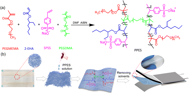 | ||
| Scheme 1 (a) Synthesis scheme of PPES. (b) Schematic illustration of the fabrication process of rQPE. | ||
2. Results and discussion
2.1. Synthesis and characterization of PPES
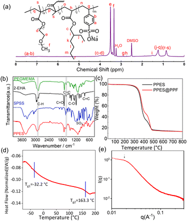
PPES is chemically synthesized via the radical copolymerization of poly(ethylene glycol) methyl ether methacrylate) (PEGMEMA), 2-ethylhexyl acrylate (2-EHA) and sodium (p-styrene sulfonate) (SPSS) with poly (ethylene glycol)dimethacrylate (PEGDMA, 15 mol%) as a cross-linker as shown in Scheme. 1a. Generally, for the fabrication of QPEs, polymers endowed with high ionic conductivity and high mechanical strength are always preferred. In the current design, PEGMEMA with strong Li+/EO affinity is selected as the side chain of PPES to provide fast segmental dynamics and mechanical flexibility, leading to improved ionic conductivity. To improve the mechanical strength, SPSS monomer with a rigid molecular structure was also utilized for copolymerization followed by chemically cross-linking with PEGDMA to form a robust polymer network. To study the effect of crosslinking density, a series of polymers with different molar ratios of crosslinkers were synthesized and evaluated as shown in Fig. S1 (ESI†). The PPES with 5 mol% of PEGDMA is soft with low mechanical strength and can even be dissolved in an organic solvent. In contrast, with 25 mol% of the crosslinker, the polymer film becomes brittle and cannot form a free-standing film. Herein, PPES with 15 mol% of PEGDMA is selected in this study for further evaluation.The chemical structure of the as-prepared PPES was characterized by 1H NMR and FT-IR spectra. As illustrated in the FT-IR spectra in Fig. 1b, the peaks lying at ≈2950 cm−1 for all samples correspond to the stretching vibration of C–H units. For PEGMEMA, 2-EHA and PPES, the peaks at ≈1720 cm−1 are assigned to the stretching vibration of –C![[double bond, length as m-dash]](https://www.rsc.org/images/entities/char_e001.gif) O. The characteristic peaks at 1630 cm−1 assigned to the –C
O. The characteristic peaks at 1630 cm−1 assigned to the –C![[double bond, length as m-dash]](https://www.rsc.org/images/entities/char_e001.gif) C unit are obvious in the FT-IR spectra of PEGMEMA, 2-EHA and SPSS monomers. While in the spectrum of PPES, much weaker peaks around 1630 cm−1 can be observed, suggesting the polymerization of monomers, which can also be confirmed in the 1H NMR results. As shown in comparative 1H NMR spectra of PPES and monomers in Fig. 1a and Fig. S2 (ESI†), the absence of proton signals between 5 and 6.5 ppm corresponding to the alkene group indicates the near complete reaction of feeding monomers. The characteristic peak of methyl units at the chain end of 2-EHA (peak i in Fig. S2 (ESI†) and peak r–s in Fig. 1a) manifests the successful chemical bonding of 2-EHA to the polymer network, which could provide spontaneous adhesion with the compositing fibers.38
C unit are obvious in the FT-IR spectra of PEGMEMA, 2-EHA and SPSS monomers. While in the spectrum of PPES, much weaker peaks around 1630 cm−1 can be observed, suggesting the polymerization of monomers, which can also be confirmed in the 1H NMR results. As shown in comparative 1H NMR spectra of PPES and monomers in Fig. 1a and Fig. S2 (ESI†), the absence of proton signals between 5 and 6.5 ppm corresponding to the alkene group indicates the near complete reaction of feeding monomers. The characteristic peak of methyl units at the chain end of 2-EHA (peak i in Fig. S2 (ESI†) and peak r–s in Fig. 1a) manifests the successful chemical bonding of 2-EHA to the polymer network, which could provide spontaneous adhesion with the compositing fibers.38
The thermal stability of samples was measured using a simultaneous thermal analyzer at a heating rate of 10 °C min−1 from room temperature to 800 °C in a N2 atmosphere. The result demonstrates that the as-prepared PPES shows good thermal stability without significant weight loss until 350 °C (Fig. 1c). Moreover, by thermally treating the rQPE and commercial separator under the same conditions (Fig. S3, ESI†), the separator becomes significantly wrinkled while the rQPE retains the original shape, demonstrating excellent thermal stability. Generally, as polymer electrolytes, the glass transition temperature (Tg) should be lower than the operating temperature of the battery to endow fast segmental dynamics.39 Herein, as identified using the differential scanning calorimetry (DSC) curve shown in Fig. 1d, two glass transition processes lying at −32.2 °C and 163.6 °C separately are observed. The presence of two Tgs manifests the microphase separation between polar and nonpolar units. At ambient temperature, the soft segments contribute to film flexibility that can accommodate the volume variation of the Li electrode whereas the rigid component shows mechanical robustness. The microphase separation is confirmed by the small-angle X-ray scattering (SAXS) spectrum with a broad peak at 0.18 nm−1 (Fig. 1e), corresponding to a characteristic length of ∼33 nm.
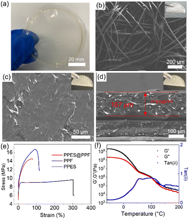
As shown in Fig. 2a, a freestanding, optically clear, flexible PPES film can be obtained after casting the as-prepared PPES polymer solution into a Teflon dish and then removing the solvent under vacuum. The PPES film exhibits a Young's modulus of 52 MPa (an ultimate tensile strength of 4 MPa as shown in Fig. 2e). Employed as a QPE, a high mechanical strength, especially after swelling with a large amount of liquid electrolyte, is crucial for the cell to prevent the potential (micro) short circuit under abused operation.40,41 To improve the mechanical strength, the PPF with a diameter of ≈20 µm was employed (Fig. 2b). It can be seen that PPF films composed of entangled fibers show a Young's modulus of ∼190 MPa (an ultimate tensile strength of 16.7 MPa).
The fiber-reinforced polymer film can be successfully fabricated by imbedding the PPF into the PPES solution, followed by drying in a vacuum oven. As shown in Fig. 2c, the flexible and freestanding PPES@PPF film demonstrates a smooth and compact surface. The cross-sectional SEM image (Fig. 2d) shows that the thickness of the as-prepared fiber-reinforced polymer electrolyte is ∼167 µm with the PPF uniformly distributed in the PPES polymer matrix. Tensile test demonstrates that the obtained flexible PPES@PPF has a fracture strain of 77% with an ultimate tensile strength of ∼14.5 MPa (comparable Young′s modulus to PPF). The mechanical properties of PPES are also evaluated by dynamic mechanical analysis (DMA) in a temperature range of −60 to 200 °C. As shown in Fig. 2f, the higher storage modulus (G′) than loss modulus (G″) (tan![[thin space (1/6-em)]](https://www.rsc.org/images/entities/char_2009.gif) δ < 1) in the evaluated temperature range suggests the solid-like behavior of the synthesized PPES.42 In the temperature range of 50–100 °C, the modulus of PPES exhibits a plateau-like behavior with comparable values of G′ and G″ (≈106 Pa), indicating the high mechanical strength of PPES. The robust mechanical strength of PPES@PPF is attributed to the chemically crosslinked structure of PPES and the physically reinforced entangled fiber structure of PPF. With such mechanically reinforced properties, when the film is swelled with a liquid electrolyte, “well-connected” Li+ transport channels can be formed in the rQPE, rendering high ionic conductivity and uniform Li+ transport. Moreover, with both physical and chemical reinforcement, these “well-connected” channels can be retained even under high charging/discharging current density or suffering from huge volume variation of Li electrode.
δ < 1) in the evaluated temperature range suggests the solid-like behavior of the synthesized PPES.42 In the temperature range of 50–100 °C, the modulus of PPES exhibits a plateau-like behavior with comparable values of G′ and G″ (≈106 Pa), indicating the high mechanical strength of PPES. The robust mechanical strength of PPES@PPF is attributed to the chemically crosslinked structure of PPES and the physically reinforced entangled fiber structure of PPF. With such mechanically reinforced properties, when the film is swelled with a liquid electrolyte, “well-connected” Li+ transport channels can be formed in the rQPE, rendering high ionic conductivity and uniform Li+ transport. Moreover, with both physical and chemical reinforcement, these “well-connected” channels can be retained even under high charging/discharging current density or suffering from huge volume variation of Li electrode.
2.2. Electrochemical performance of rQPE
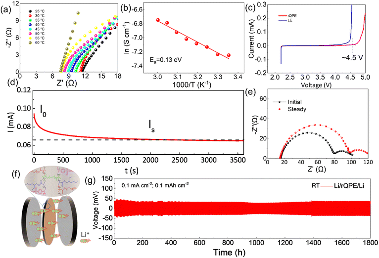
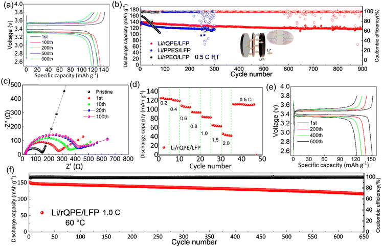
Apart from high mechanical strength, an ideal QPE should also possess high ionic conductivity, which is closely related to the electrolyte uptake ratio. As shown in Table S1 (ESI†), the as-prepared PPES@PPF film has a high electrolyte uptake ratio of (83.7 ± 2.1)% with a high ionic conductivity of 1.1 and 0.45 mS cm−1 at 60 °C and 25 °C, respectively (Fig. 3a and Fig. S4, ESI†). The high electrolyte uptake ratio can be ascribed to the unique chemical component and cross-linked structure of PPES, in which, high binding affinities can be formed between the abundant ethylene oxide (EO) units and the liquid electrolyte.34 Due to this strong EO–solvent interactions, the solvent molecules are confined to the polymer network, creating stable “well-connected” Li+ transport channels for facilitating ion transport. Moreover, the PPF in the cross-linked polymer chains can better stabilize this “well-connected” structure. All these factors contribute to a high electrolyte uptake ratio and superior ionic conductivity. As shown in Fig. 3b, the temperature–ionic conductivity curve fitted by Vogel–Fulcher–Tammann (VFT) behavior shows a low activation energy of 0.13 eV, suggesting a fast ion migration dynamics for rQPE. The electrochemical stability of the as-synthesized rQPE is evaluated by linear sweep voltammetry (LSV, Fig. 3c). The onset potential for the decomposition of rQPE is ≈4.5V, implying the potential application of rQPE in batteries with a high-voltage cathode, such as LiNi0.8Mn0.1Co0.1O2 (NMC811). The improved electrochemical stability of rQPE is probably because the trapped solvent molecules by polymer network can better withstand electrochemical oxidation. The polymer electrolyte with a high Li+ transport number is beneficial for inhibiting Li dendrites and undesirable side reactions due to their potential to reduce the buildup of ion concentration gradients.43–47 According to previous reports,43,48,49 the sulfonate anions in SPSS generally display low pairing strength with Li+, which could enhance the transport of Li+, reaching higher ionic conductivity. As shown in Fig. 3d and e and Table S2 (ESI†), the cationic transport number (tLi+), according to the Bruce-Vincent method for rQPE is calculated to be 0.59 ± 0.07, which is higher than that of the commonly used polymer electrolyte systems (tLi+ < 0.4), suggesting an excellent Li+ dominant transportation in rQPE.50To investigate the electrolyte/electrode interfacial dynamic stability, the Li/rQPE/Li symmetric cell was assembled and evaluated (Fig. 3f). As shown in Fig. 3g, at a current density of 0.1 mA cm−2, the Li/rQPE/Li symmetric cell exhibits stable cycling performance over 1800 h with overpotential less than 50 mV, demonstrating highly stable Li reversibility and effective inhibition of dendritic Li during the cycling process.51,52 The Li/rQPE/LFP full cell was also assembled to evaluate the cycling stability of the as prepared polymer electrolyte. As shown in Fig. 4a, at a current density of 0.2C for initial 3 cycles, the Li/rQPE/LFP cell has an initial discharge capacity of 129.6 mA h g−1 with an initial CE of 91.5%. With the current density of 0.5C for subsequent cycles as shown in Fig. 4b, the Li/rQPE/LFP cell exhibits stable cycling performance with a capacity retention of 91% (based on the 1st cycle) and an average CE of 99.1% after 900 cycles. In contrast, without the PPF as the reinforcing wire, the full cell with a PPES-based QPE (Li/PPES/LFP) was short circuited after mere 300 cycles. The remarkably improved cycling stability of the Li/rQPE/LFP cell demonstrates that the PPF in rQPE plays a crucial role in stabilizing Li electrodes. With high mechanical strength, the rQPE can effectively inhibit the Li dendrite growth, contributing to superior cycling stability. Aside from the PPF, the designed polymer components and structure also contribute significantly to the enhanced cycling performance. To prove such assumption, the coin cell with a fiber-reinforced PEO (rPEO) as the polymer electrolyte, i.e., Li/rPEO/LFP, was also assembled, which exhibits a high initial discharge capacity of 166 mA h g−1 while poor cycling stability (Fig. 4b). This is probably due to the fact that the as-prepared rPEO has high ionic conductivity while absence of efficient adhesion units. Therefore, the PEO cannot be tightly bonded with the PPF fiber, leading to micro structural damage of the electrolyte during the repeated charging/discharging process.
To further understand the superior electrochemical performance of the cell with rQPE, the electrochemical impedance spectroscopy (EIS) analysis was used to evaluate the interfacial stability of Li electrodes during the cycling process. As shown in Fig. 4c, increased charge-transfer resistance (Rct) can be obtained for the Li/rQPE/LFP cell with initial 20 cycles. After 20 cycles, stable Rct can be observed, suggesting the formation of a stable electrode/electrolyte interface. As illustrated by the rate capability of the Li/rQPE/LFP cell in Fig. 4d, even at a current density of 1.0C, a discharge capacity of ∼80 mA h g−1 can be obtained. When the current density returns back to 0.5C, a high discharge capacity can still be obtained, indicating the good rate capability of the cell. The Li/rQPE/LFP cell was also tested at 60 °C to evaluate the high-temperature stability of the rQPE (Fig. 4e and f). At a current density of 1.0C, the Li/rQPE/LFP cell delivers a high reversible discharge capacity of 116.4 mA h g−1 after 650 cycles with a capacity retention of 77% and an average CE of 99.2%. Moreover, the electrochemical performance of cells with quasi-solid polymer electrolytes reported in previous reports is summarized in Table S3 (ESI†). It can be seen that the current Li/LFP full cell exhibits stable cycling performance with a capacity retention of 91% over 900 cycles, superior than the cell in previous reports.53–62 Moreover, the symmetric cell with such a fiber-reinforced quasi-solid polymer electrolyte can also be stably cycling over 1800 h at 0.1 mA cm−2.
The excellent electrochemical performance can be explained by the following reasons. First, by integrating the high ionic conductivity and high mechanical strength into a single polymer electrolyte, the as-prepared QPE can effectively maintain the structural integrity and suppress the potential (micro-) short circuit of the cell. As shown in Fig. 2e, the fiber reinforced film exhibits a Young's modulus of ≈190 MPa with a decent ultimate tensile strength (≈14.5 MPa), which is much higher than that of the pure PPES polymer film, i.e., an ultimate tensile strength of only 4 MPa. With this high mechanical modulus, “well-connected” Li+ transport channels can be formed and retained, contributing to superior charge transfer kinetics and drastically reduced local flux heterogeneity of Li+ and thus stable cycling stability (capacity retention of 91% after 900 cycles for Li/rQPE/LFP cell vs. short circuit after mere 300 cycles for Li/PPES/LFP cell). Second, the as-prepared QPE can trigger the formation of a conformal and stable SEI layer on the Li metal electrode. As shown in Fig. 5a–e and Fig. S5 (ESI†), the chemical compositions of Li electrodes from Li/rQPE/LFP and Li/LE/LFP cell after cycling for 50 cycles were analyzed via the X-ray photoelectron spectroscopy (XPS). In the C1s spectrum, the peaks at 284.8, 286.5 and 289 eV can be assigned to C–C, C–O and O![[double bond, length as m-dash]](https://www.rsc.org/images/entities/char_e001.gif) C–O species, respectively.63–65 The peak at 293 eV is due to the presence of LiTFSI on the Li metal surface, which agrees well with the peak detected in the F1s spectrum. The –F functional units can trigger the formation of LiF species on the Li electrodes (Fig. 5b and d), which has an ultrahigh shear modulus (55.1 GPa) that can effectively suppress the Li dendrite growth.66 In the C1s spectra of the Li electrode from the Li/LE/LFP cell, apart from the C–C, C–O and O
C–O species, respectively.63–65 The peak at 293 eV is due to the presence of LiTFSI on the Li metal surface, which agrees well with the peak detected in the F1s spectrum. The –F functional units can trigger the formation of LiF species on the Li electrodes (Fig. 5b and d), which has an ultrahigh shear modulus (55.1 GPa) that can effectively suppress the Li dendrite growth.66 In the C1s spectra of the Li electrode from the Li/LE/LFP cell, apart from the C–C, C–O and O![[double bond, length as m-dash]](https://www.rsc.org/images/entities/char_e001.gif) C–O species, the peak assigned to thermodynamically unstable and brittle Li2CO3 is detected, while not that significant in the electrode from the Li/rQPE/LFP cell. In the Li1s spectra of the Li electrode from the Li/LE/LFP cell, the contents of Li2CO3 and Li2O are higher than those of the electrode from the Li/rQPE/LFP cell, indicating a conformal and stable SEI layer on Li metal. Third, the enhanced adhesion arising from the presence of 2-EHA functional units leads to a seamless electrolyte/electrode contact and dramatically decreased interfacial resistance. As shown in Fig. 5f, after cycling for 50 cycles, the LFP cathode is tightly bonded with the polymer electrolyte, and the peel off process leads to the separation of aluminum foil and the LFP cathode (Fig. S6, ESI†).
C–O species, the peak assigned to thermodynamically unstable and brittle Li2CO3 is detected, while not that significant in the electrode from the Li/rQPE/LFP cell. In the Li1s spectra of the Li electrode from the Li/LE/LFP cell, the contents of Li2CO3 and Li2O are higher than those of the electrode from the Li/rQPE/LFP cell, indicating a conformal and stable SEI layer on Li metal. Third, the enhanced adhesion arising from the presence of 2-EHA functional units leads to a seamless electrolyte/electrode contact and dramatically decreased interfacial resistance. As shown in Fig. 5f, after cycling for 50 cycles, the LFP cathode is tightly bonded with the polymer electrolyte, and the peel off process leads to the separation of aluminum foil and the LFP cathode (Fig. S6, ESI†).
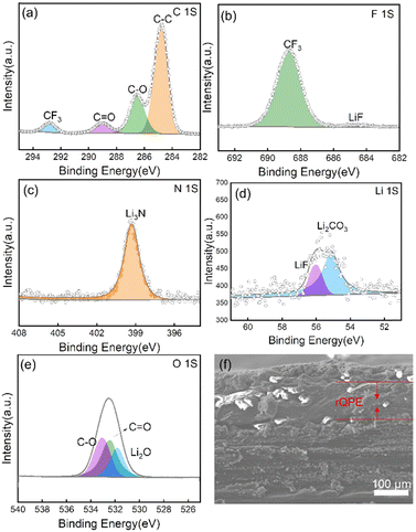 | ||
| Fig. 5 XPS spectra of Li electrodes after cycling for 50 cycles: (a) C1s, (b) F1s, (c) N1s, (d) Li1s, and (e) O1s. (f) Cross-sectional SEM image of Li/rQPE/LFP after cycling for 50 cycles. | ||
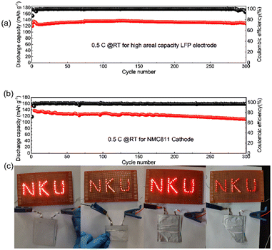
Towards high-energy density rechargeable batteries, high areal capacity is always preferred. To evaluate the electrochemical performance of the as-prepared rQPE for potential high-energy density rechargeable batteries, commercial LFP (C-LFP; 96.8 wt% active material, >2 mA h cm−2 based on one side of active materials) was utilized for the assembled Li/rQPE/C-LFP cell. As shown in Fig. 6a, at a current density of 0.5C, the cell exhibits stable cycling performance with a capacity retention of 97% and an average CE of 99.6% over 300 cycles, suggesting great potential of such fiber-reinforced QPEs towards practical quasi-solid-state LMBs. Moreover, to further evaluate the battery with coupled high-voltage cathode, the cell with ultra-thin QPE (tQPE, ∼10 µm, consisting of PPES, 5 µm ultra-thin film and carbonate electrolyte as shown in Fig. S7a and b, ESI†) and high-voltage LiNi0.8Mn0.1Co0.1O2 (NMC811) cathode was also assembled. The EO units in PPES show high affinities with the carbonate liquid electrolyte (ethylene carbonate/dimethyl carbonate), and effectively trap the solvent molecules in the polymer framework.34 In this network, the Li cations are fully solvated by solvent molecules to form locally highly concentration Li+, while the other solvent molecules are fastened by the polymer matrix in QPEs.31 As a result, “well-connected” Li+ transport channels are formed, leading to excellent electrochemical performance. As shown in Fig. 6b, the cell delivers stable cycling performance over 300 cycles with a capacity retention of 80%. A 10 mA h Li/rQPE/LFP pouch cell was also assembled to verify the extensibilities of the as-prepared rQPE in LMBs. It can be seen that, light emitting diode (LED) lights can be powered by the assembled cell. Due to the fiber reinforcement in the rQPE, the LED can still be powered even after folding, nail penetration and cutting into pieces (Fig. 6c and Video S1, ESI†), suggesting the ultra-safety of such QPE-based batteries.
3. Conclusions
In summary, by incorporating the poly(propylene) fiber with a rationally designed, multi-component elastic polymer network, a fiber-reinforced QPE is obtained. Due to the chemically crosslinked structure of the polymer film, the physically reinforced entangled fiber and efficient absorption of liquid electrolyte, the resulting well-designed QPE successfully surpasses the trade-off between mechanical strength and ionic conductivity in typical solid electrolytes, achieving excellent electrochemical performance of assembled LMBs. The assembled Li/rQPE/LFP cell exhibits stable cycling performance with a capacity retention of 91% over 900 cycles. Towards high-energy density rechargeable batteries, the cell with commercial high areal capacity LFP as the cathode delivers a discharge capacity of 128.3 mA h g−1 after 300 cycles (a capacity retention of 97%). Moreover, with ultra-thin QPE (tQPE, ≈10 µm) and a high-voltage NMC811 cathode, the Li/tQPE/NMC811 cell still exhibits a capacity retention of 80% and an average CE of 97.4% over 300 cycles, suggesting the great potential of this design towards practical application in quasi-solid-state Li-metal batteries. The successful improvement of both ionic conductivity and mechanical strength will provide guidance on the design and utilization of QPEs towards safe, high-energy density batteries with a prolonged lifetime.Author contributions
S. Gao., P.-F. Cao and H. Yang conceived the research and designed the experiments. S. Gao, Y. Zhang, Z. Li, M. Ma and Z. Sun performed material fabrication and characterization. H. Yang, M. Tian and P. Cao revised the grammar in use and property characterization studies. The manuscript was written through contributions of all authors. All authors have given approval to the final version of the manuscript.Conflicts of interest
There are no conflicts to declare.Acknowledgements
S. Gao, Y. Zhang, M. Ma and Z. Li are supported by the Natural Science Foundation of China (21421001), China Postdoctoral Science Foundation (2021M701769), the Natural Science Foundation of Tianjin, China (18JCZDJC31400), and the MOE Innovation Team (IRT13022). P.-F. Cao acknowledges financial support by Fundamental Research Funds for the Central Universities (buctrc202222).Notes and references
- M. A. Cabañero Martínez, N. Boaretto, A. J. Naylor, F. Alcaide, G. D. Salian, F. Palombarini, E. Ayerbe, M. Borras and M. Casas-Cabanas, Adv. Energy Mater., 2022, 12, 2201264 CrossRef.
- P. Albertus, V. Anandan, C. Ban, N. Balsara, I. Belharouak, J. Buettner-Garrett, Z. Chen, C. Daniel, M. Doeff, N. J. Dudney, B. Dunn, S. J. Harris, S. Herle, E. Herbert, S. Kalnaus, J. A. Libera, D. Lu, S. Martin, B. D. McCloskey, M. T. McDowell, Y. S. Meng, J. Nanda, J. Sakamoto, E. C. Self, S. Tepavcevic, E. Wachsman, C. Wang, A. S. Westover, J. Xiao and T. Yersak, ACS Energy Lett., 2021, 6, 1399–1404 CrossRef CAS.
- M. Du, K. Liao, Q. Lu and Z. Shao, Energy Environ. Sci., 2019, 12, 1780–1804 RSC.
- Z. Yu, X. Zhang, C. Fu, H. Wang, M. Chen, G. Yin, H. Huo and J. Wang, Adv. Energy Mater., 2021, 11, 2003250 CrossRef CAS.
- Q. Zhao, S. Stalin, C. Z. Zhao and L. A. Archer, Nat. Rev. Mater., 2020, 5, 229–252 CrossRef CAS.
- S. Gao, Z. Li, N. Liu, G. Liu, H. Yang and P. F. Cao, Adv. Funct. Mater., 2022, 32, 2202013 CrossRef CAS.
- C. Song, Z. G. Li, J. Peng, X. H. Wu, H. Peng, S. Y. Zhou, Y. Qiao, H. Sun, L. Huang and S. G. Sun, J. Mater. Chem. A, 2022, 10, 16087–16094 RSC.
- Y. Qiao, H. J. Yang, Z. Chang, H. Deng, X. Li and H. S. Zhou, Nat. Energy, 2021, 6, 653–662 CrossRef CAS.
- J. Wu, S. Liu, F. Han, X. Yao and C. Wang, Adv. Mater., 2021, 33, 2000751 CrossRef CAS PubMed.
- W. Lu, M. Xue and C. Zhang, Energy Storage Mater., 2021, 39, 108–129 Search PubMed.
- S. Gao, A. Cannon, F. Sun, Y. Pan, D. Yang, S. Ge, N. Liu, A. P. Sokolov, E. Ryan, H. Yang and P.-F. Cao, Cell Rep. Phys. Sci., 2021, 2, 100534 CrossRef CAS.
- F. He, W. Tang, X. Zhang, L. Deng and J. Luo, Adv. Mater., 2021, 33, 2105329 CrossRef CAS PubMed.
- S. Gao, F. Sun, N. Liu, H. Yang and P.-F. Cao, Mater. Today, 2020, 40, 140–159 CrossRef CAS.
- Y. An, Y. Cheng, S. Wang and J. Yu, ACS Appl. Energy Mater., 2022, 5, 2786–2794 CrossRef CAS.
- Z. Yu, P. E. Rudnicki, Z. Zhang, Z. Huang, H. Celik, S. T. Oyakhire, Y. Chen, X. Kong, S. C. Kim, X. Xiao, H. Wang, Y. Zheng, G. A. Kamat, M. S. Kim, S. F. Bent, J. Qin, Y. Cui and Z. Bao, Nat. Energy, 2022, 7, 94–106 CrossRef CAS.
- S. H. Hong, D. H. Jung, J. H. Kim, Y. H. Lee, S. J. Cho, S. H. Joo, H. W. Lee, K. S. Lee and S. Y. Lee, Adv. Funct. Mater., 2020, 30, 1908868 CrossRef CAS.
- Q. Lu, C. Wang, D. Bao, H. Duan, F. Zhao, K. D. Davis, Q. Zhang, R. Wang, S. Zhao, J. Wang, H. Huang and X. Sun, Energy Environ. Mater., 2023, e12447 Search PubMed.
- X. Zou, Q. Lu, Y. Zhong, K. Liao, W. Zhou and Z. Shao, Small, 2018, 14, 1801798 CrossRef PubMed.
- J. Wu, Z. Rao, Z. Cheng, L. Yuan, Z. Li and Y. Huang, Adv. Energy Mater., 2019, 9, 1902767 CrossRef CAS.
- J. H. Sun, J. Y. Peng, T. R. Y. Ring, L. Whittaker-Brooks, J. E. Zhu, D. Fraggedakis, J. Niu, T. Gao and F. Wang, Energy Environ. Sci., 2022, 15, 5284–5299 RSC.
- Z. Li, S. Wang, J. Shi, Y. Liu, S. Zheng, H. Zou, Y. Chen, W. Kuang, K. Ding, L. Chen, Y.-Q. Lan, Y.-P. Cai and Q. Zheng, Energy Storage Mater., 2022, 47, 262–270 CrossRef.
- S. Hao, L. Li, W. Cheng, Q. Ran, Y. Ji, Y. Wu, J. Huo, Y. Yang and X. Liu, J. Mater. Chem. A, 2022, 10, 4881–4888 Search PubMed.
- L. Ye and X. Li, Nature, 2021, 593, 218–222 CrossRef CAS PubMed.
- L. Fan, S. Wei, S. Li, Q. Li and Y. Lu, Adv. Energy Mater., 2018, 8, 1702657 CrossRef.
- S. K. Vineeth, M. Tebyetekerwa, H. Liu, C. B. Soni Sungjemmenla, X. S. Zhao and V. Kumar, Mater. Adv., 2022, 3, 6415–6440 RSC.
- N. Meng, F. Lian and G. Cui, Small, 2021, 17, 2005762 CrossRef CAS PubMed.
- W. Zhou, S. Wang, Y. Li, S. Xin, A. Manthiram and J. B. Goodenough, J. Am. Chem. Soc., 2016, 138, 9385–9388 CrossRef CAS PubMed.
- Y. Ma, Q. Sun, Z. Wang, S. Wang, Y. Zhou, D. Song, H. Zhang, X. Shi, C. Li, L. Zhang and L. Zhu, J. Mater. Chem. A, 2021, 9, 3597–3604 RSC.
- Y. Liu, L. Hou, Y. Jiao and P. Wu, ACS Appl. Mater. Interfaces, 2021, 13, 13319–13327 CrossRef CAS PubMed.
- L. Yang, J. Zhang, W. Xue, J. Li, R. Chen, H. Pan, X. Yu, Y. Liu, H. Li, L. Chen and X. Huang, Adv. Funct. Mater., 2022, 32, 2200096 CrossRef CAS.
- X. He, Y. Ni, Y. Hou, Y. Lu, S. Jin, H. Li, Z. Yan, K. Zhang and J. Chen, Angew. Chem., Int. Ed., 2021, 60, 22672–22677 CrossRef CAS PubMed.
- D. Zhou, R. Liu, Y.-B. He, F. Li, M. Liu, B. Li, Q.-H. Yang, Q. Cai and F. Kang, Adv. Energy Mater., 2016, 6, 1502214 CrossRef.
- T. T. Zuo, Y. Shi, X. W. Wu, P. F. Wang, S. H. Wang, Y. X. Yin, W. P. Wang, Q. Ma, X. X. Zeng, H. Ye, R. Wen and Y. G. Guo, ACS Appl. Mater. Interfaces, 2018, 10, 30065–30070 CrossRef CAS PubMed.
- Q. Lu, Y. B. He, Q. Yu, B. Li, Y. V. Kaneti, Y. Yao, F. Kang and Q. H. Yang, Adv. Mater., 2017, 29, 1604460 Search PubMed.
- Y. H. Li, Z. J. Sun, D. Y. Liu, Y. Y. Gao, Y. K. Wang, H. T. Bu, M. T. Li, Y. F. Zhang, G. X. Gao and S. J. Ding, J. Mater. Chem. A, 2020, 8, 2021–2032 RSC.
- Z. Zhang, Y. Huang, C. Li and X. Li, ACS Appl. Mater. Interfaces, 2021, 13, 37262–37272 CrossRef CAS PubMed.
- X. Zhang, S. Zhao, W. Fan, J. Wang and C. Li, Electrochim. Acta, 2019, 301, 304–311 CrossRef CAS.
- S. Gao, Y. Pan, B. Li, M. A. Rahman, M. Tian, H. Yang and P. F. Cao, Adv. Funct. Mater., 2022, 33, 2210543 CrossRef.
- S. Gao, Z. Li, Z. Zhang, B. Li, X. C. Chen, G. Yang, T. Saito, M. Tian, H. Yang and P.-F. Cao, Energy Storage Mater., 2023, 55, 214–224 CrossRef.
- C. Monroe and J. Newman, J. Electrochem. Soc., 2003, 150, A1377–A1384 CrossRef CAS.
- Z. Zeng, X. Chen, M. Sun, Z. Jiang, W. Hu, C. Yu, S. Cheng and J. Xie, Nano Lett., 2021, 21, 3611–3618 CrossRef CAS PubMed.
- Y. Pan, S. Ge, Z. Rashid, S. Gao, A. Erwin, V. Tsukruk, K. D. Vogiatzis, A. P. Sokolov, H. Yang and P.-F. Cao, ACS Appl. Energy Mater., 2020, 3, 3387–3396 CrossRef CAS.
- J. Zhu, Z. Zhang, S. Zhao, A. S. Westover, I. Belharouak and P. F. Cao, Adv. Energy Mater., 2021, 11, 2003836 CrossRef CAS.
- H. O. Ford, B. Park, J. Jiang, M. E. Seidler and J. L. Schaefer, ACS Mater. Lett., 2020, 2, 272–279 CrossRef CAS.
- Z. Chen, D. Steinle, H.-D. Nguyen, J.-K. Kim, A. Mayer, J. Shi, E. Paillard, C. Iojoiu, S. Passerini and D. Bresser, Nano Energy, 2020, 77, 105129 CrossRef CAS.
- P. Kuray, W. Mei, S. E. Sheffield, J. Sengeh, C. R. F. Pulido, C. Capparelli, R. J. Hickey and M. A. Hickner, Front. Energy Res., 2020, 8, 569387 Search PubMed.
- X. Shan, S. Zhao, M. Ma, Y. Pan, Z. Xiao, B. Li, A. P. Sokolov, M. Tian, H. Yang and P. F. Cao, ACS Appl. Mater. Interfaces, 2022, 14, 56110–56119 Search PubMed.
- E. R. Parnham and R. E. Morris, J. Mater. Chem., 2006, 16, 3682–3684 RSC.
- M. V. O'Reilly, H. Masser, D. R. King, P. C. Painter, R. H. Colby, K. I. Winey and J. Runt, Polymer, 2015, 59, 133–143 CrossRef.
- S. L. Gao, M. X. Zhang, C. Gainaru, A. P. Sokolov, H. B. Yang and P. F. Cao, Matter, 2022, 5, 2457–2460 CrossRef CAS.
- Y. Guo, X. Qu, Z. Hu, J. Zhu, W. Niu and X. Liu, J. Mater. Chem. A, 2021, 9, 13597–13607 RSC.
- H. Huo, J. Gao, N. Zhao, D. Zhang, N. G. Holmes, X. Li, Y. Sun, J. Fu, R. Li, X. Guo and X. Sun, Nat. Commun., 2021, 12, 176 CrossRef CAS PubMed.
- W. Lin, X. Zheng, S. Ma, K. Ji, C. Wang and M. Chen, ACS Appl. Mater. Interfaces, 2023, 15, 8128–8137 CrossRef CAS PubMed.
- X. Zeng, L. Dong, J. Fu, L. Chen, J. Zhou, P. Zong, G. Liu and L. Shi, Chem. Eng. J., 2022, 428, 131100 CrossRef CAS.
- H. Xu, S. Huang, J. Qian, S. Liu, L. Li, X. Zhao and W. Zhang, Colloids Surf., A, 2022, 653, 130040 CrossRef CAS.
- J. Wang, C. Tao, J. Cao, X. Jiao, L. Wang and T. Liu, ChemElectroChem, 2022, 9, 202200957 Search PubMed.
- J. Ma, X. Ma, H. Zhang, F. Chen, X. Guan, J. Niu and X. Hu, J. Membr. Sci., 2022, 659, 120811 CrossRef CAS.
- Y. Jin, X. Zong, X. Zhang, Z. Jia, H. Xie and Y. Xiong, Energy Storage Mater., 2022, 49, 433–444 CrossRef.
- X. Fu, M. J. Hurlock, C. Ding, X. Li, Q. Zhang and W. H. Zhong, Small, 2022, 18, 2106225 CrossRef CAS PubMed.
- S. Chai, Y. Zhang, Y. Wang, Q. He, S. Zhou and A. Pan, eScience, 2022, 2, 494–508 Search PubMed.
- P. Liu, L. Zhong, S. Wang, S. Huang, D. Han, Z. Huang, M. Xiao and Y. Meng, Energy Storage Mater., 2023, 58, 132–141 CrossRef.
- Z. Wang, H. Shi, W. Zheng, W. Sun, L. Zhao and W. Yuan, J. Power Sources, 2022, 524, 231070 CrossRef CAS.
- Y. Sun, Y. Zhao, J. Wang, J. Liang, C. Wang, Q. Sun, X. Lin, K. R. Adair, J. Luo, D. Wang, R. Li, M. Cai, T. K. Sham and X. Sun, Adv. Mater., 2019, 31, 1806541 CrossRef PubMed.
- J. Zhao, L. Liao, F. Shi, T. Lei, G. Chen, A. Pei, J. Sun, K. Yan, G. Zhou, J. Xie, C. Liu, Y. Li, Z. Liang, Z. Bao and Y. Cui, J. Am. Chem. Soc., 2017, 139, 11550–11558 Search PubMed.
- K. Leung, F. Soto, K. Hankins, P. B. Balbuena and K. L. Harrison, J. Phys. Chem. C, 2016, 120, 6302–6313 CrossRef CAS.
- Z. A. Yu, D. G. Mackanic, W. Michaels, M. Lee, A. Pei, D. W. Feng, Q. H. Zhang, Y. C. Tsao, C. V. Amanchukwu, X. Z. Yan, H. S. Wang, S. C. Chen, K. Liu, J. Kang, J. Qin, Y. Cui and Z. N. Bao, Joule, 2019, 3, 2761–2776 CrossRef CAS.
Footnotes |
| † Electronic supplementary information (ESI) available. See DOI: https://doi.org/10.1039/d3ma00078h |
| ‡ These authors contributed equally to this work. |
| This journal is © The Royal Society of Chemistry 2023 |

