
 Open Access Article
 This Open Access Article is licensed under a Creative Commons Attribution-Non Commercial 3.0 Unported Licence
Quantitative framework development for understanding the relationship between doping and photoelectrochemical energy conversion of TiO2†
Aparna
Markose
 ,
Debanita
Das
and
Prasanth
Ravindran
*
,
Debanita
Das
and
Prasanth
Ravindran
*
Nano Photonics Laboratory, Department of Green Energy Technology, UNESCO Madanjeet School of Green Energy Technologies, Pondicherry University, Pondicherry, 605014, India. E-mail: prasanth.ravindran@gmail.com
First published on 22nd June 2023
Abstract
Efficient energy harvesting devices are required to achieve sustainable development goals. Titania is a semiconductor that has attracted substantial research attention in pursuit of energy independence since it is an abundant, stable, toxin-free, and energy-prospective substance. Careful tailoring of morphological and electronic properties is required to address the poor conductivity of TiO2 to achieve competitive Power Conversion Efficiency (PCE). Adding an optimum amount of impurity to TiO2 is one of the prominent methods to increase its conductivity. This review critically analyzes doping of TiO2 in light of the power conversion efficiencies of various electrochemical cells. This review suggests an alternative quantitative framework for developing and establishing the relationship between doping and photoelectrochemical energy conversion in TiO2-based devices. It offers an alternative for accurate data reporting after a careful analysis of the PCE data in research articles and data reporting processes now in use. This study provides information on data analysis, visualization, and contemporary techniques for doping TiO2.
 Aparna Markose | Aparna Markose received her Master of Physics degree from the University of Calicut, Kerala, in 2014 and received a Master of Green Energy Technology from Pondicherry University in 2019 with Distinction. She is now a Research Scholar at Madanjeet School of Green Energy Technologies, Pondicherry University. Her research interests are designing and developing heterostructures, one-dimensional and zero-dimensional nano-systems for energy conversion. |
 Debanita Das | Debanita Das is pursuing her PhD from the Indian Institute of Technology Bombay (IITB) – Monash University Joint Research Academy. She is currently studying the impact of plasmonic structures on optical sensing-based applications. She is working under the joint supervision of Prof. Anshuman Kumar (IITB) and Prof. Alison Funston (Monash University). She had completed her Master's in Green Energy Technology from Pondicherry University and graduated as a gold medalist. |
 Prasanth Ravindran | Dr. Prasanth Ravindran is professor at Madanjeet School of Green Energy Technologies, Pondicherry University. He received his PhD from the Eindhoven University of Technology, Netherlands, for the thesis entitled “Photonic switching in III–V nanostructures.” He pursued his post-doctoral research at the Peter Debye Institute at Utrecht University. His current research interest is developing one-dimensional and zero-dimensional nano-systems for energy conversion. |
1. Introduction
Titanium dioxide (titania, TiO2) is a semiconductor with diverse applications in solar cells, catalysts, sunscreens, medicine, inks, wastewater treatment, water splitting, energy storage, and electrochemical cells1–4 (Fig. 1). The properties of titanium dioxide such as its wide bandgap, charge injection, extraction-favored band edge alignments, long excited electron lifetime, abundance, chemical inertness, and resistance to photocorrosion make it an excellent material for photovoltaic applications. TiO2 has three natural polymorphs: anatase, rutile, and brookite (Fig. 2). Anatase and rutile have the same tetragonal structure, while brookite is orthorhombic. Even though brookite is the most stable form, anatase exhibits low recombination and superior charge transfer properties.5–8 Employing titanium dioxide for photoelectrochemical conversion became a milestone in the history of dye-sensitized solar cells (DSSCs).9 Until the discovery of Grätzel cells, DSSCs performed poorly due to their low photon absorption.10 Other wide bandgap semiconductors such as ZnO, SnO2, and Nb2O5 have been used in DSSCs instead of TiO2.11,12 The abundance, stable and trouble-free production of mesoporous particles, non-toxicity, stability, and apposite band alignment with popular dye N719 made TiO2 the most suitable electrode material for DSSCs.12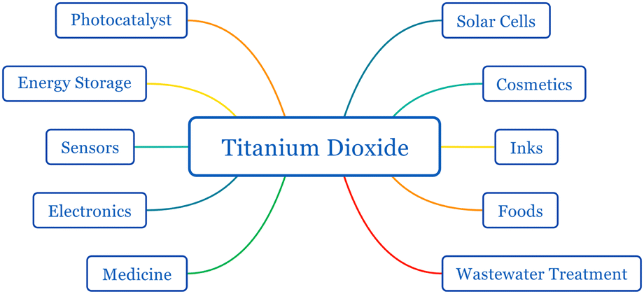 | ||
| Fig. 1 Applications of titanium dioxide. | ||
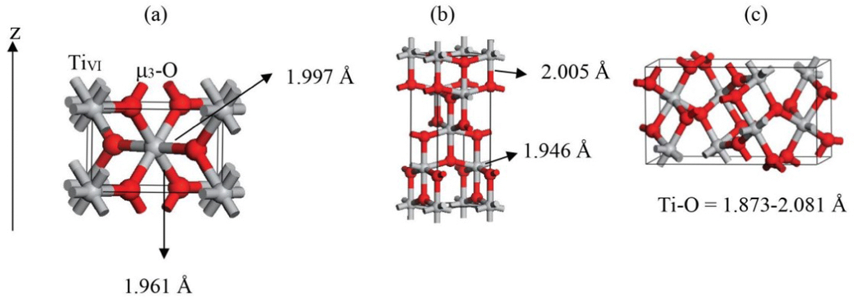 | ||
| Fig. 2 Structures of TiO2 natural polymorphs: (a) rutile, (b) anatase and (c) brookite.17 | ||
The limitations of other organic-based solar cells have been an ongoing focus of DSSC research due to the explosive growth of the perovskite solar cell industry over the past five years. Whereas the majority of PV technologies fail to succeed, humidity, oxygen conditions, and an easy production process are favorable for DSSCs.13 One significant benefit of DSSCs is their exceptional power production in all lighting circumstances, even indoor lighting. It has been found that under diffused or dim sunlight conditions silicon based solar cells do not perform well.13–15 This requirement gap is satisfied by DSSCs in an efficient and competitive way. Indoor light harvesting using DSSCs even surpassed 30 percentage without co-sensitizers. For wireless sensor nodes, consumer electronics, wearable technology, and smart meters, DSSCs can be implemented indoors as portable electronic modules.16 The potential to scale up and that to minimize production costs are key game changers in DSSC research. Because of their potential for indoor lighting, DSSCs can maximize energy efficiency while minimizing their carbon footprint.
In DSSCs, the current is generated when a dye molecule absorbs a photon and injects an electron into the semiconductor's conduction band. The circuit is completed when the dye is degenerated by the electrolyte's redox species. This electrolyte is then reduced at the counter electrode, which is usually platinum. A monolayer dye absorbs approximately 1% of the incident monochromatic light. In order to increase the photon absorption, Grätzel cells were equipped with stable dyes and high surface area TiO2 films. These transparent, nonporous titanium dioxide films increased the absorption of incident solar energy to 46%.18 According to Henry J. Snaith, it is possible to attain a maximum efficiency of 20.25 percent in DSSCs. Photovoltaic loss in a DSSC originates from the following (Fig. 3): (a) incomplete light harvesting, (b) inefficient electron transfer, where absorbed photons are diverted to non-injecting channels, (c) heterogeneity of dye and the semiconductor band alignment, which results in an “overpotential” to unify the electron transfer, (d) energy loss when dye relaxation causes a conformational change in the dye structure (this change causes electrons to diffuse into the oxide with lower energy), and (e) dye regeneration which causes a potential drop of around 0.3 eV, eventually leading to the most significant single loss in the DSSC. Considering these, reducing the difference between the optical bandgap of the absorber and the open circuit voltage increases the Power Conversion Efficiency (PCE).
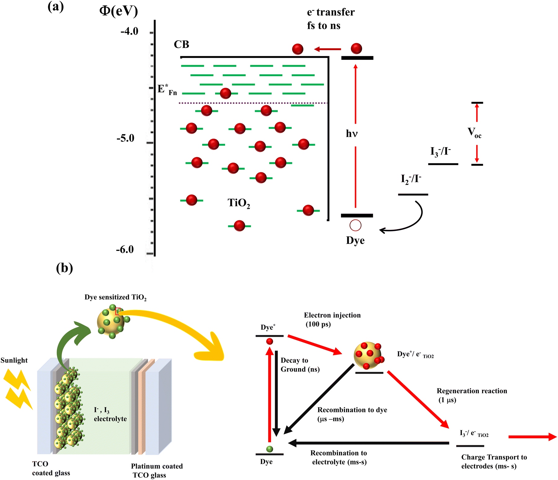 | ||
| Fig. 3 (a) Illustration of the energy level of the DSSC.20 (b) Charge transfer and recombination mechanisms involved in the DSSC.27 | ||
By lowering the bandgap between the semiconductor and sensitizer, it is possible to reduce the loss in potential by a factor of 0.2 eV. When the dye is strongly coupled to TiO2, it broadens the absorption width and rearranges the optical bandgap of the DSSC. Hence the DSSC's optical bandgap cannot be determined from the sensitizer's absorption alone. Furthermore, the optical bandgap can be estimated only from the sensitized electrode's absorption onset values.19
Fundamental quantities that affect the PCE are the open circuit voltage (Voc), short circuit current (Jsc), and fill factor (FF) of DSSCs. Jsc depends on the charge collection efficiency of TiO2 and the light absorption efficiency of dye. The open circuit voltage depends on the valence band (VB) of the hole transport material (HTM), the band configuration of TiO2, and recombination inside the DSSC. The fill factor accounts for the resistive losses in the DSSC circuit. The more sophisticated and vigilant the architecture, the better the FF. It is essential to engineer the CB of TiO2 and the CB/lowest unoccupied molecular orbital (LUMO) of the hole transport material for higher Voc and improved electron injection to enhance PCE.
Device power output is determined by the TiO2/dye/electrolyte interface's charge separation and collection. According to the detailed energetics, forward kinetic processes are light absorption, electron injection, dye regeneration and charge transport.21–26 The thermodynamically downhill loss pathways are excited state decay to the ground state, electron recombination to dye and electron recombination to electrolyte (Fig. 3(b)). The appreciable point in here is that the efficiency of electron injection in DSSCs depends on the magnitude of these injection kinetics relative to excited state decay to the ground state. It is also noteworthy to mention that fast electron injection dynamics requires strong electronic coupling of the dye LUMO to the metal oxide conduction-band states and energetically accessible TiO2 density of states from the excited state of the dye. The key to achieving maximum efficiency devices lies in minimizing free energy losses, while maintaining high quantum efficiencies.27
The electron injection rate (kinj) can be expressed as the sum of all electron transfer processes as follows:
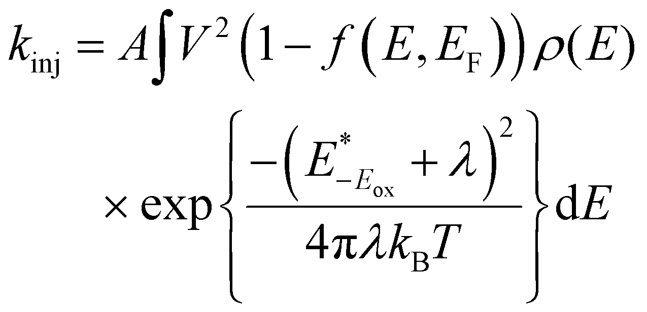
 is the redox potential of the dye excited state, ρ(E) is the density of semiconductor acceptor states at energy E relative to NHE, V is the average electronic coupling between the dye excited state and different states in the semiconductor with the same energy E, f(E,EF) is the Fermi occupancy factor for each semiconductor acceptor state which can be determined from the semiconductor electron Fermi level EF and λ is the total reorganization energy for electron injection.28 The TiO2 conduction band density of states increases exponentially in the presence of electrolyte. This exponentially increasing density is explained by the localized intraband states corresponding to the Ti4+ sites which reduce to Ti3+ when subjected to oxygen vacancies or in the presence of more electronegative impurities. The exponentially increasing DOS originates from an inhomogeneous distribution of conduction band edge energies. An example of this type of system is nanoparticle crystals showing inhomogeneous surfaces and charge.29
Doping plays a significant role in PCE by affecting the morphology and particle size of TiO2 and changing the conduction band edge DOS. These intentional changes induced via doping influence the TiO2–dye interaction and determine the energetics. If the doping favors the injection dynamics, the PCE increases. If the acceptor DOS potential (Semiconductor, TiO2) and injection state energy (Dye excitation) potential match, there will be a three-fold increase in the injection kinetics (kinj).30–35 Surprisingly, the importance of electron injection and its influence on PCE is not considered widely. One of the reasons for this negligence is the early model systems which indicated an increase in photocurrent with increased proton/lithium concentration. The studies employing ultrafast transient absorption spectroscopy showed that the injection dynamics in N719 sensitized TiO2 films was two orders of magnitude slower in the presence of typical redox electrolyte.36–44 However, recent studies have employed time correlated single photon counting to measure injection kinetics and correlated these measurements with photocurrent. In these cases, a correlation was observed between the efficiency of electron injection and photocurrent density. These studies are in perfect agreement with IPCE data, and transient kinetic studies.34,35,45–49
TiO2 is a natural n-type semiconductor with a 3.2 eV bandgap and an electrical resistivity of 1013–1018 Ohm cm.50,51 According to DOS calculations, the extreme upper end of the valence band is dominated by O 2pπ orbitals, and the bottom of the conduction band consists of isolated Ti 3dxy orbitals.52 Decreasing the resistivity of TiO2 is the key to increasing the efficiency of DSSCs. Once the electron is injected, two highly undesirable yet unavoidable reactions occur in DSSCs. Injected photo-induced electrons (i) recombine with oxidized dye molecules and (ii) react with the electrolyte to produce iodide. This recombination reduces the number of electrons traveling through the designated pathways to complete the DSSC circuit; consequently, the PCE is reduced.53 We can resolve these issues by increasing the conductivity of TiO2, by improving the dye–TiO2 interaction by refining the band alignment and increasing the surface area of TiO2 to increase the dye loading.
The most crucial property in increasing the efficiency of a DSSC, the conductivity of TiO2, depends on its carrier concentration, carrier separation, charge collection efficiency, and charge transport efficiency.54–57 Conductivity is directly proportional to charge mobility and carrier concentration. Charge mobility indicates a carrier's ability to move through the material under an electric field. This is linked with charge transport and collection efficiency. Oxygen vacancies, titanium interstitials, and the presence of impurities and defects in the structures can improve the conductivity.50,52,58 Introducing elements into the TiO2 lattice disturbs the conduction band and forms subbands below the CB. These can be either from the formation of Ti3+ or from the impurity which replaced Ti4+. These n type defects can increase the carrier concentration and boost the conductivity. Moreover, if electrons from deep trap states which lie in the DOS tail are freed, they will also promote conductivity.59
HTM and TiO2 share a delicate interface in DSSCs. This heterojunction creates a space charge region, indicating an energy level difference between the CB of TiO2 and HTM, causing a band bending. An external voltage that cancels out this band bending is called the flat band potential (Vfb). Negative shift in the existing Vfb will result in an upward shift of the CB and Fermi level and vice versa. The upward shift in the CB reduces the efficiency of electron injection. Nevertheless, an intentional impurity causing a downward shift in the CB by introducing defects makes electron injection efficient.60 Throughout the discussion, doping is identifiable as a trivial method for increasing the conductivity of TiO2, hence improving the PCE of DSSCs.
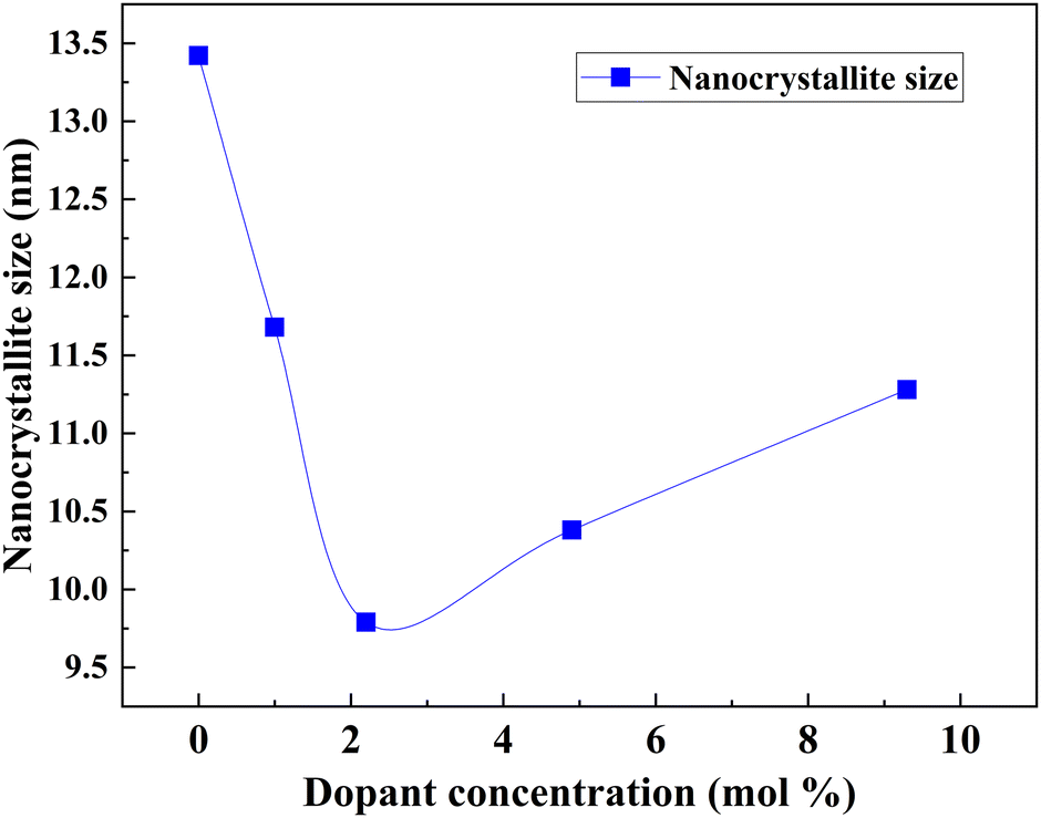
Electrodes require higher sunlight harvesting efficiency, photoelectron injection efficiency, and electron collection efficiency in order to increase PCE. The surface area and absorption coefficient of TiO2 determine how effectively sunlight is captured. If doping changes the morphology and increases the surface area without altering the active TiO2 mass, it can enhance PCE through light absorption. Photoelectron injection efficiency kinetics is dependent on the density of states in the conduction band. The photocurrent density fluctuates as a result of how the flat band potential influences the conduction band density. Electron collection efficiency is determined by electron transport, electron transfer resistance and electron recombination. The crystallite size of doped TiO2 is connected to the density of states and electron kinetics. Throughout the review, with available data, we explain how doping affects the flat band potential and PCE. The bandgap too plays an influencing role in recombination dynamics. All the recombination pathways are connected to conduction band and surface states. Three major charge recombination pathways are direct transfer from the conduction band to electrolyte, indirect transfer from monoenergetic deep surface states, and indirect transfer from the distribution of bandgap surface states. Understanding how the bandgap changes with doping is the primary step in tackling the recombination.
Doping is an incredible way to engineer the electronic properties of materials. Since the first report of TiO2 photovoltaic properties, there has been a growing trend in the research industry to increase the conductivity of TiO2. Fig. 4 shows conclusive evidence for ongoing and booming research in doping TiO2. Doping TiO2 for improving the physical and morphological properties is well-known in solar cell research. In DSSCs, TiO2 acts as a photoanode that facilitates electron transportation from the dye to the conductive oxides. This anode requires high absorbance, a reduced bandgap, and a low recombination rate for better performance. Doping affects all these properties by altering the morphology and structural properties. For example, Ag and Ni doping make TiO2 more porous, and the size and shape of big particles become irregular. Also, doping creates a sponge-like structure, increasing the surface area and the efficiency of light absorption. Single doping, co-doping, doping into a composite, and growing delicate designs with doped TiO2 have been tried for efficiency enhancement in DSSCs.61
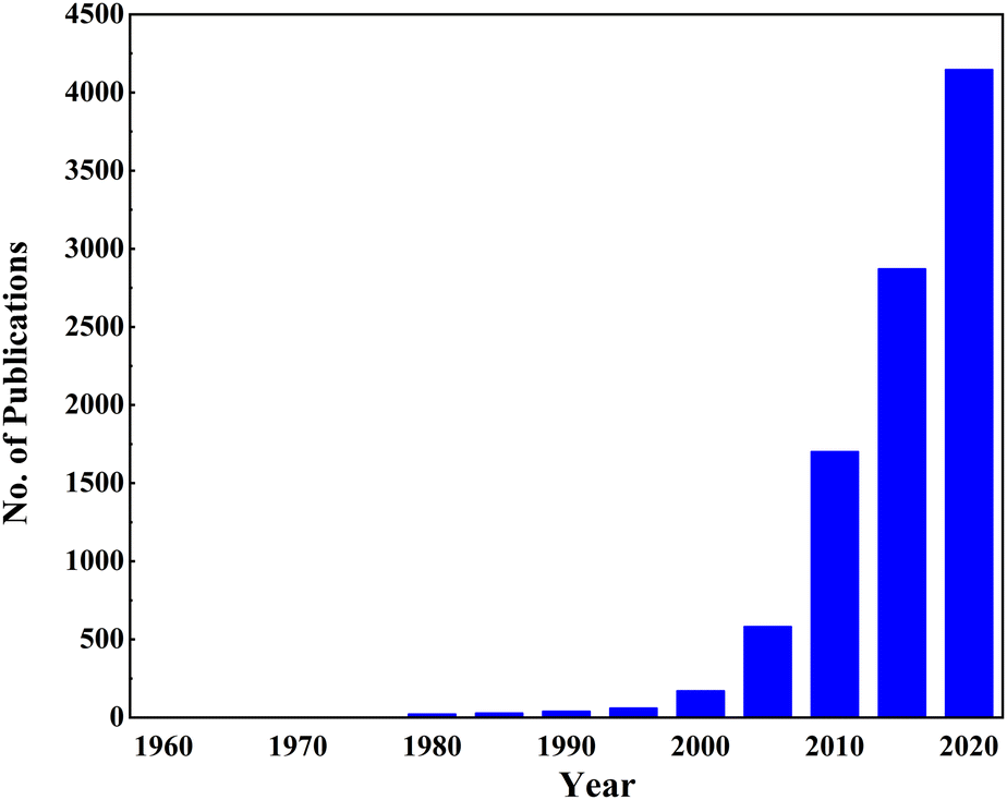 | ||
| Fig. 4 Growing trend of TiO2 doping (Articles published from 1960 to 2020 using the keywords “TiO2” and “Doping” on the ScienceDirect website, scrutinized by checking their relevance). | ||
Although TiO2 is the most suitable candidate as a photoanode material in terms of abundance and non-toxicity, it is a poor conductor. Generations of researchers have doped TiO2 with various elements in the periodic table. A comprehensive view is essential to understanding doping and its effect on materials properties to engineer a new material. Many reviews have been published based on doping in TiO2 since the beginning of interest. There are reviews about doping of TiO2 to increase the efficiency of DSSCs, the fundamental mechanisms and properties of TiO2 photoanodes, and different TiO2 fabrication methods.1,62–64 In doped TiO2, the cell efficiency varied with the doping strategy. Hence, this review creates a framework for analyzing the effect of doping by normalizing the increase in efficiency. Up until this point, doping has been reported as changing the DSSC output if there is a change in efficiency. However, there are errors involved in this type of analysis. When the preparation method is sophisticated, we get higher efficiency solar cells for undoped TiO2.65 Different researchers have reported different efficiencies for bare TiO2-based DSSCs. This ambiguity in bare DSSCs’ efficiency makes it difficult to find the effect of doping. There are undoped TiO2-based DSSCs with less than 1% efficiency and above 5%.65,66 The efficiency of DSSCs based on undoped TiO2 changed between 0.019 and 9.05%.65–75 To understand how a dopant affects the performance of DSSCs, we need to reframe the understanding of how the Power Conversion Efficiency (PCE) changes when we add a tiny amount of dopant into TiO2. This review provides a detailed summary of the effect of doping of TiO2 on its photoconversion efficiency based on the performance of the DSSC. However, the trends predicted with this analysis help optimize TiO2-based thin-film heterojunction solar cells and PEC hydrogen production.
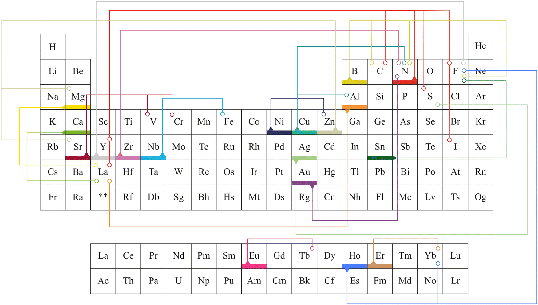
Alkali metals, alkaline earth metals, transition metals, lanthanoids, post-transition metals, metalloids, non-metals, and halogen were doped into TiO2 to increase the efficiency of electrochemical cells.76–84 Elements doped into TiO2 for electrochemical applications are marked in Fig. 5. This review is structured to discuss doping and co-doping separately in different electrochemical systems. Single elemental doping will be discussed based on the periodic element group-wise. Codoping is categorized into three main sections: metal doping, non-metal doping, and metal–nonmetal doping. A detailed discussion of bandgap tuning, size effects with doping, and different preparation methods of doped TiO2 is included. The review structure is illustrated in Fig. 6.
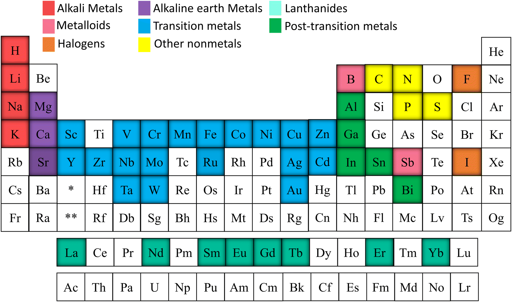 | ||
| Fig. 5 Elements doped into TiO2 included in this review. | ||
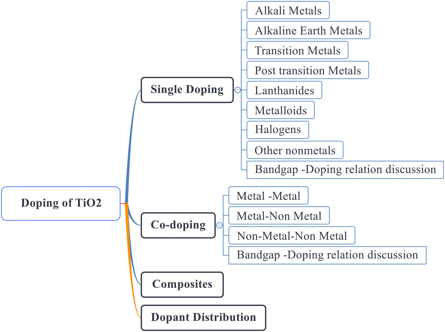 | ||
| Fig. 6 Structure of this review. | ||
2. Framework for analyzing the impact of dopants in DSSCs
The impact of a dopant on the efficiency of a DSSC is estimated from the percentage increase/decrease in efficiency calculated using eqn (1):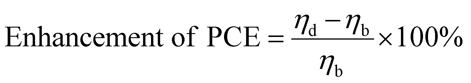 | (1) |
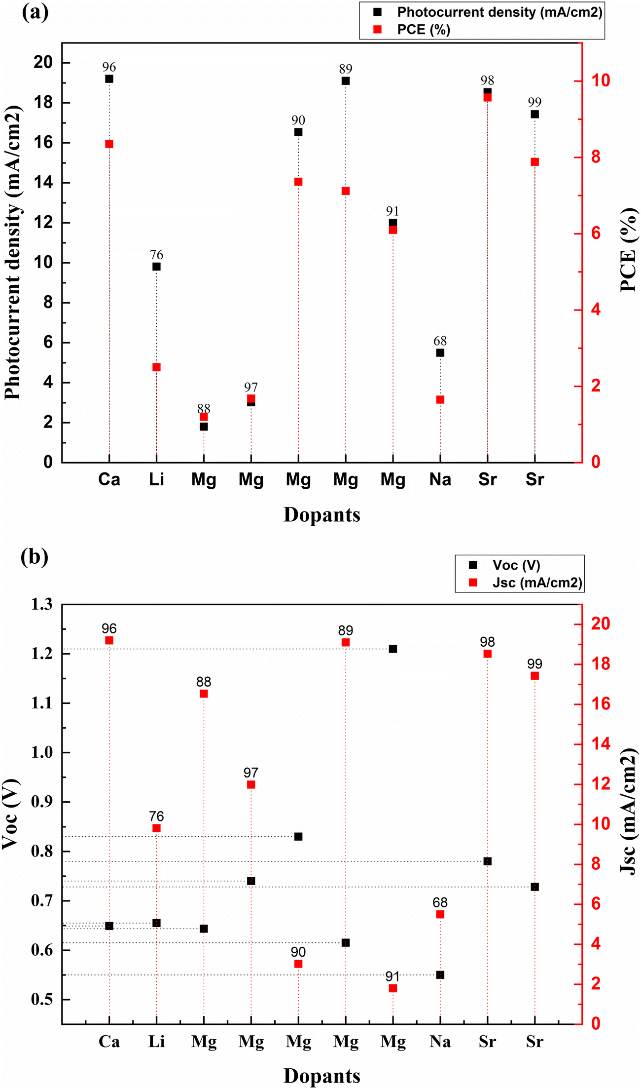
Fig. 8 is obtained after calculating the percentage increase in PCE on doping TiO2 with alkali and alkaline earth metal dopants using eqn (1). The analysis shows that among all the alkali and alkaline earth metals explored to date, Sr dopant has the maximum impact on the efficiency enhancement of the bare TiO2 photoanode when treated with TiCl4, and a scattering layer is introduced. However, if we consider only the impact of the dopant alone on a bare TiO2 photoanode, then Mg and Na are the potential dopants.
3. Single elemental doping
Doping a semiconductor increases the conductivity and tunes its optical properties. Metal dopants block recombination and enhance the driving force for electron injection. They also form complexes that enhance dye binding on the surface of TiO2. Hence the overall power conversion efficiency can be enhanced. TiO2 is doped with various elements in the periodic table to adjust its optical and electrical characteristics. This section discusses single elemental doping on TiO2 in groups. Alkali metals, alkaline earth metals, transition metals, and post-transition metals are all thoroughly discussed. Lanthanoids, metalloids, halogens, and other non-metals are also extensively investigated for doping TiO2. The link between doping and the bandgap is examined using presented bandgap data.3.1. Alkali metals
The alkali metal group consists of lithium, sodium, potassium, rubidium, cesium, and francium. All the elements in this group have their outermost electron in the s-orbital. Usually, these metals are all shiny, soft, and highly reactive. Among alkali metals, sodium and lithium were doped into TiO2 to enhance the PCE of solar cells. Table 1 lists the most recent Jsc, Voc, and PCE data of alkali metals.| S. no. | Dopant | Treatment/coating | Structure | Synthesis method | V oc (V) | Photocurrent density (mA cm−2) | FF | PCE (%) | Enhancement in PCE (%) | Bandgap (eV) | Application | Sensitizer/dye | Ref. |
|---|---|---|---|---|---|---|---|---|---|---|---|---|---|
| 1 | Lithium (Li) | Nanoparticles | Hydrothermal | 0.655 | 9.81 | 0.358 | 2.5 | 362.96 | DSSC | N719 | 76 | ||
| 2 | Sodium (Na) | Nanorods | Hydrothermal | 0.55 | 5.5 | 0.545 | 1.65 | 79.35 | DSSC | Extract from petals of Hibiscus sabdariffa (Roselle) | 68 | ||
| 3 | Calcium (Ca) | Nanorods | Hydrothermal | 0.649 | 19.2 | 0.67 | 8.35 | 13.92 | DSSC | N3 | 96 | ||
| 4 | Magnesium (Mg) | Thin films | Aerosol assisted chemical vapor deposition | 0.74 | 11.99 | 0.67 | 6.1 | 81.55 | 2.8 | DSSC | N719 | 97 | |
| 5 | Magnesium (Mg) | Thin films | Dip coating | 0.83 | 3.02 | 0.668 | 1.68 | 2.98 | DSSC | N719 | 90 | ||
| 6 | Magnesium (Mg) | Nanoparticles | Hydrothermal | 0.615 | 19.1 | 0.605 | 7.12 | 12.13 | DSSC | N3 | 89 | ||
| 7 | Magnesium (Mg) | Nanoparticles | Solvothermal | 1.21 | 1.8 | 0.55 | 1.2 | 66.67 | DSSC | Alkoxysilyl-coumarin dye | 91 | ||
| 8 | Magnesium (Mg) | Nanoparticles | Solvothermal microwave irradiation (SMI) technique | 0.6435 | 16.536 | 0.692 | 7.36 | 190.91 | 3.638 | DSSC | N3 | 88 | |
| 9 | Strontium (Sr) | TiCl4 | Nanoparticles | Chemical hydrolysis | 0.78 | 18.53 | 0.66 | 9.57 | 249.27 | DSSC | N719 | 98 | |
| 10 | Strontium (Sr) | Nanoparticles | Hydrothermal | 0.728 | 17.43 | 0.62 | 7.88 | 12.73 | 3.05 | DSSC | 99 |
 | ||
| Fig. 7 (a) Performance of alkali & alkaline earth metal doped TiO2 based DSSCs. (b) Voc and Jsc values of alkali & alkaline earth metal doped TiO2 based DSSCs. Data points are labelled with references. | ||
 | ||
| Fig. 8 Percentage increase in PCE due to alkaline and alkali metal doping. Data points are labelled with references. | ||
3.2. Alkaline earth metals
Elements with an oxidation state of +2 and having a full outer s-orbital belong to alkaline earth metals. They have a shiny, silvery appearance. These elements usually exhibit low density, melting point, and boiling point values. Magnesium, calcium, and strontium are some potential dopant candidates that can enhance the photocurrent and efficiency of DSSCs by modifying TiO2 electrode properties.3.3. Lanthanoids
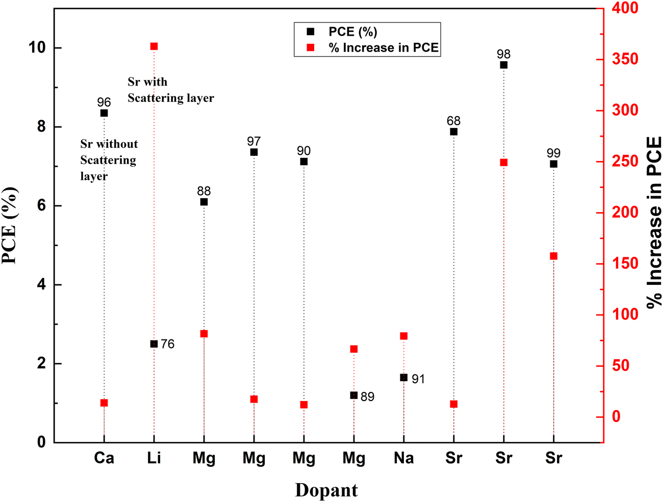
Rare earth elements offer sharp and stable luminescence ideal for optoelectronic uses. Rare earth elements such as lanthanum (La),101–103 neodymium (Nd),80 samarium (Sm),104,105 europium (Eu),70 gadolinium (Gd),106 terbium (Tb),107 erbium (Er),108,109 and ytterbium (Yb)108–113 have been doped into TiO2 to improve its optoelectronic properties.77,80,104,107 Coupling of weakened ligands arising from 4f orbital shielding by 6s, 5p, and 5d orbitals and forbidden f–f transitions works in favor of stable and sharp luminescence for rare-earth ions. Due to their insolubility and thermal quenching, there were limitations in incorporating rare-earth ions into various semiconductors. However, combustion processing, sol–gel, hydrothermal, solvothermal and ball milling methods have made rare-earth doping possible.Lanthanoids effectively alter the absorption range of semiconductors by enhancing visible photons’ absorption. All but one lanthanide have significant chemistry associated with 4f orbital filling. 4f orbitals are effective in the adsorption of pollutants and increase photocatalysis. The 5d electronic configuration of these ions contributes to high charge mobility and redox coupling. Lanthanoids are utilized to reduce the bandgap of TiO2 and increase the surface area. There is an existing conflict regarding the position of lanthanum ions after doping. Some researchers claim that no rare earth elements can penetrate the TiO2 lattice due to their larger ionic size. They tend to either be in the surface interstitial of TiO2 or create Ti–O–La bonding on the surface. This bonding enhances the oxygen vacancies and surface area of TiO2. Doping with rare earth elements improves the photovoltaic performance of TiO2-based devices. However, there are also reports regarding La3+ located in the crystallite interstitials. This penetration can inhibit crystal growth as well.114 The PCE performance of the Lanthanide group elements doped into TiO2 is illustrated in Fig. 12(a) and (b). The statistics of doping and its effects are listed in Table 2.
| S. no. | Dopant | Structure | Synthesis method | V oc (V) | Photocurrent density (mA cm−2) | FF | PCE (%) | Enhancement in PCE (%) | Bandgap (eV) | Application | Sensitizer/dye | Ref. |
|---|---|---|---|---|---|---|---|---|---|---|---|---|
| 1 | Europium (Eu) | Nanophosphors | Combustion and doctor blade | 0.67 | 18.53 | 0.709 | 8.8 | 5.77 | 3.32 | DSSC | N719 | 70 |
| 2 | Europium (Eu) | Nanoparticles | Sol–gel, doctor blade | 0.77 | 9.61 | 0.69 | 5.16 | 21.99 | DSSC | N719 | 105 | |
| 3 | Gadolinium (Gd) | Spheres | Hydrothermal and spray pyrolysis | 0.723 | 7.749 | 0.736 | 4.12 | 73.84 | DSSC | N719 | 106 | |
| 4 | Gadolinium (Gd) | Mesoporous | Solvothermal | 0.723 | 7.749 | 0.736 | 4.12 | 42.48 | DSSC | N719 | 106 | |
| 5 | Neodymium (Nd) | Anatase | Hydrothermal | 0.62 | 12.83 | 0.66 | 5.23 | 34.10 | 2.6 | DSSC | N719 | 117 |
| 6 | Neodymium (Nd) | Nanoparticles | Screen printing | 0.78 | 11.5 | 0.683 | 6.15 | 13.89 | 3.2655 | DSSC | N719 | 80 |
| 7 | Samarium (Sm) | Nanoparticles | Hydrothermal | 0.863 | 14 | 0.5032 | 6.08 | 72.72 | DSSC | N719 | 104 | |
| 8 | Samarium (Sm) | Nanoparticles | Sol–gel, doctor blade | 0.81 | 10.9 | 0.67 | 5.81 | 37.35 | DSSC | N719 | 105 |
 | ||
| Fig. 9 Crystallite size and bandgap in Nd doped TiO2.117 | ||
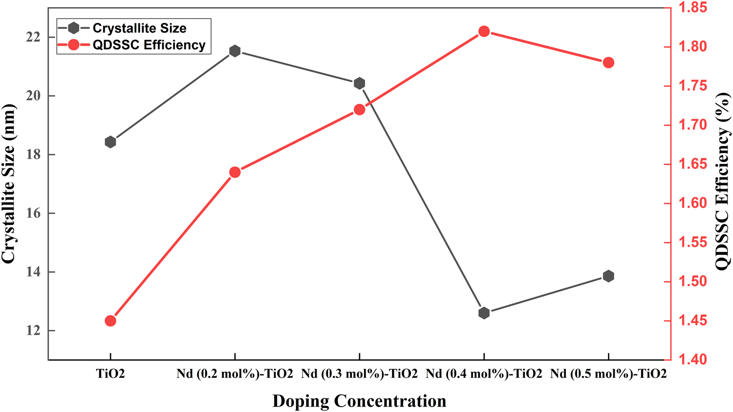 | ||
| Fig. 10 Crystallite size and efficiency in a Nd doped TiO2 based QDSSC.117 | ||
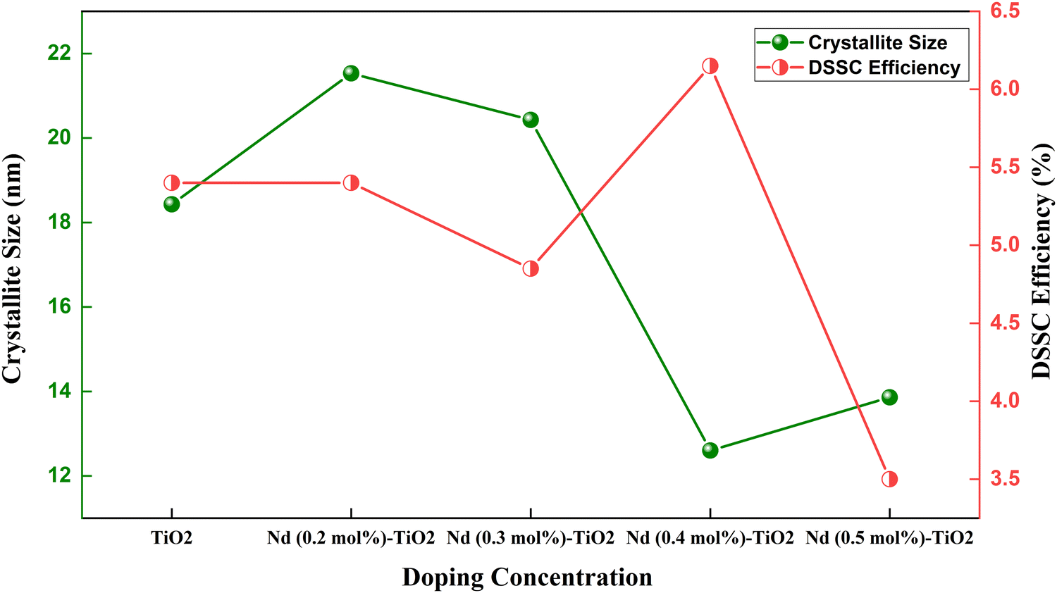 | ||
| Fig. 11 Crystallite size and efficiency in a Nd doped TiO2 based DSSC.117 | ||
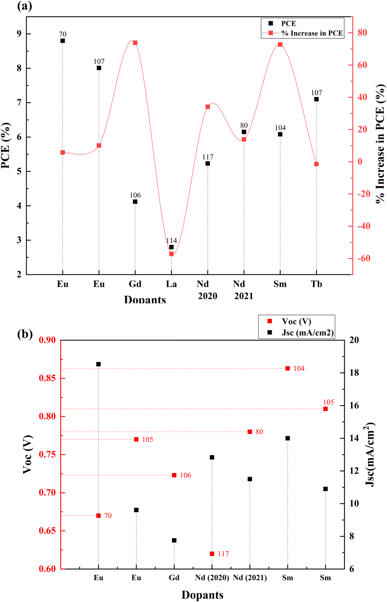 | ||
| Fig. 12 (a) Percentage increase in PCE with lanthanide doping. (b) Voc and Jsc values of lanthanoid doped TiO2 based DSSCs. Data points are labelled with references. | ||
3.4. Metalloids
Metalloids are also called semi-metals due to their mixed behavior of metals and non-metals. Boron,118,119 antimony120 and germanium121 have been doped into TiO2 for attaining better DSSC efficiencies. When doped with metalloids, it creates excess electrons in the system. Increased electron concentration will improve electron transport efficiency, enhancing photocurrent density.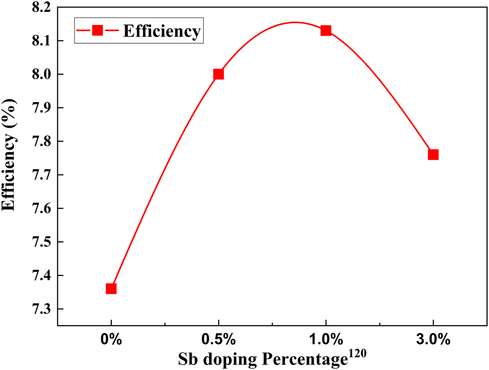 | ||
| Fig. 13 Change in PCE with Sb doping concentration.120 | ||
3.5. Transition metals
Transition metals are the largest set of cation providers in the periodic table. These elements have a partially filled d subshell or can provide cations with an incomplete d subshell. Transition metals provide a large pool of complex ions with various oxidation states. Doping TiO2 with transition metals creates additional energy levels in the CB due to the aforementioned partially filled d-orbits. This section discusses the effects of doping these elements into TiO2 such as scandium,127 vanadium,128 chromium,129,130 manganese,131–133 iron,134 cobalt,135 nickel,136 copper,137–139 zinc,140 yttrium,141 zirconium,78 niobium,142 silver,143 cadmium,144 tantalum,145 and tungsten.146The electron lifetime increases with the substitution of Ti4+ with trivalent ions such as Y3+ and Ga3+ but the transport rate decreases. In the VB group of the periodic table, as we move from top to down, the current increases (due to the increase in the concentration of carriers and reduction in film resistance), while the voltage decreases (due to the faster recombination of electrons and reduction of the energy difference between the flat band potential and the I3−/I− redox potential). Nb doping is more beneficial among the group VB elements. Group VB elements also improve the electron transport rate, improving the charge collection efficiency. The bandgap undergoes redshift, and there is also an increment in visible light absorption.
 | ||
| Fig. 14 Impact of the plasmonic behavior on percentage increase in efficiency (note: Au is used only as composites). Data points are labelled with references. | ||
Another exciting feature of Zr doping is that this transition metal accelerates the anatase to rutile transformation.167 Doping of anatase with elements have valency smaller than 4+ provides a charge compensation by forming vacancies, amplifying the ionic transport in anatase, thereby increasing the anatase to rutile transformation. However, ions with a valence higher than 4+ form Ti3+ cations and hinder the change. This high rutile content for Zr-doped TiO2 also leads to a slighter difference between the Fermi level and the redox potential of the electrolyte. A recent research study reported that Zr-doped TiO2 exhibits the lowest bandgap relative to Fe-doped, Ni-doped, and undoped TiO2. It also suggests that Zr gets doped into TiO2 on the surface and inside the lattice.72 Zr transition metal doping can improve photocatalytic performance at higher rates. The decrease in bandgap implies that it enhances the light absorption capacity of the electrode. A decreasing trend in the Voc can also be observed at a higher level of Zr concentration, suggesting an increase in recombination processes.
The optimum amount of Nb dopant results in the substitution of Ti4+ with Nb5+ so that the Ti3+ 3d1 and Nb5+ 4d0 levels exist in the nanostructure, resulting in the formation of intraband states in the structure. This improves the charge transport and driving force for electron injection from the dye to the TiO2 conduction band.171,172 Also, the Ti 3d orbital has one excess electron for each Nb5+ substitution, thus implying that an increase in electron concentration improves electron conductivity. Such improvements in electron conductivity and increment of electron injection induced by the positive shift of the CBM enhance Jsc in addition to incident photon-to-current conversion efficiency, and the suppression of surface recombination at the TiO2/electrolyte interface along with a shift in Fermi energy results in the influence of Voc. Doping TiO2 with Nb also results in the decrease in bandgap. H. Su et al. demonstrated the long-term stability of Nb doped photovoltaic devices by a 1200 h-aging test.142 The group showed a 10–20% improvement in efficiency and Jsc of Nb doped cells relative to undoped cells. Fig. 15 illustrates the influence of Nb doping on the average size of TiO2 nanoparticles. Similarly, Fig. 16 shows the variation of Voc, Jsc, FF, and efficiency with time of the Nb-doped TiO2-based DSSCs.
 | ||
| Fig. 15 Influence of Nb doping on the average size of TiO2 nanoparticles.173 | ||
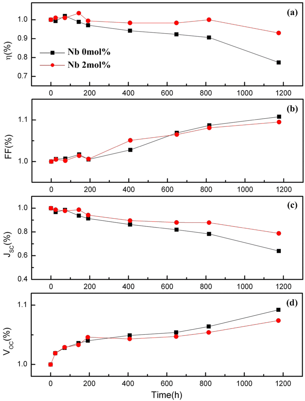 | ||
| Fig. 16 Variation of Voc, Jsc, FF and efficiency with time for Nb doped DSSCs. Reproduced from ref. 142 with permission from Elsevier.142 | ||
Nb loading influences the parent structure's morphology, pore volume, and porosity. Parameters like Jsc, Voc, and FF determine the photoelectron conversion efficiency. To achieve higher efficiency, the primary requirements are higher Jsc and larger Voc. Jsc can be determined by factors listed below:
(1) Sunlight harvesting efficiency – it is directly related to the surface area of photoanode structures that determines light scattering and dye adsorption abilities. Low Nb doping was found to be suitable for utilizing solar light effectively. However, the absorbance property was reduced, implying a reduction in surface area. With high doping, in addition to the reduction in light scattering, the structure also suffered from the reduction of dye adsorption. Thus, it has been concluded138 that the enhanced conversion efficiency should not be determined by morphological modification of Nb-doped TiO2 composite structures.
(2) Photoelectron injection efficiency – with the increase in Nb dopant, the flat band potential (Vfb) exhibited a positive shift, implying an increase in photoelectron injection (Fig. 17). The active and easy electron injection resulted in an improvement in photocurrent density. The shape and defect of the structure influence the Vfb. A smaller size might induce a positive shift of Vfb, thus increasing the photoelectron injection efficiency.
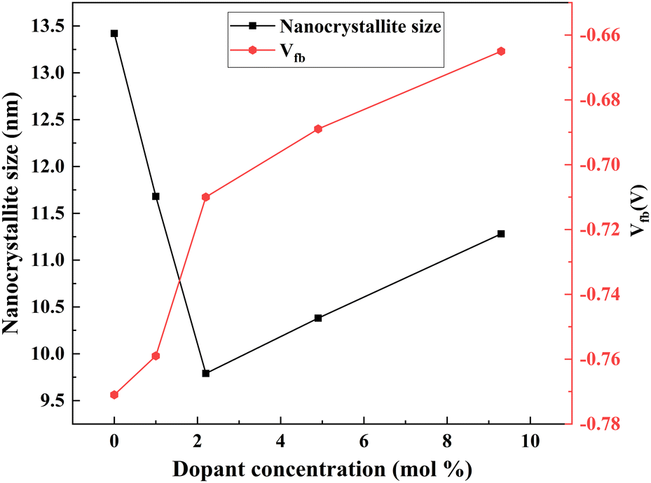 | ||
| Fig. 17 Nb dopant crystallite size and Vfb.138 | ||
(3) Electron collection efficiency – it is determined by the electron transport ability, electron transfer resistance, and electron recombination resistance. Thorough experiments are required to determine optimal doping to attain maximum electron collection efficiency (Fig. 18).
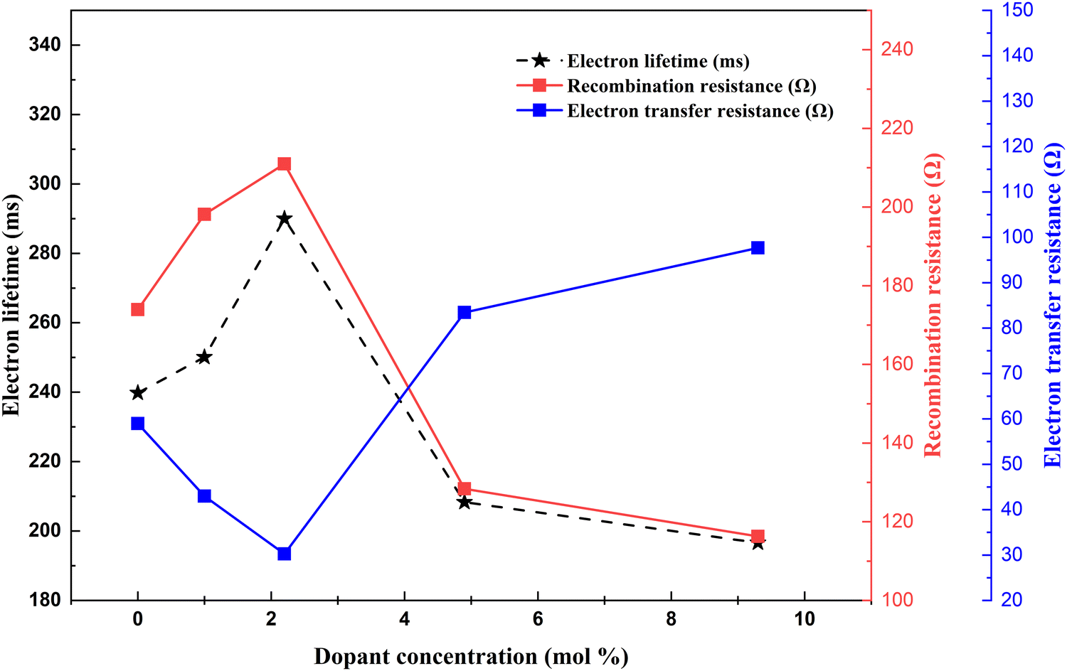 | ||
| Fig. 18 Nd dopant electron lifetime, recombination resistance and electron transfer resistance correlation.138 | ||
Another work reported the use of a blocking layer along with a Nb-doped TiO2 photoanode structure.174 DSSCs with a blocking layer exhibited pronounced increments in Voc and Jsc, which is attributed to the suppression of the electron recombination process. The advantage of using a blocking layer is that it prevents backward electron transfer at the FTO/electrolyte interface. An alternative study focusing on annealing revealed an increase in efficiency when annealing was followed by H2O2 treatment.175Fig. 19 shows how the PCE of DSSCs using Ti–Nb photoanodes with and without H2O2 treatment after annealing under different conditions and the corresponding improvement in efficiency percentage of Ti–Nb compared to Ti photoanodes.175
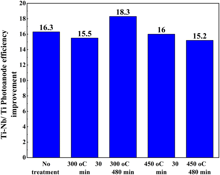 | ||
| Fig. 19 The conversion efficiency of DSSCs using Ti–Nb photoanodes with and without H2O2 treatment after annealing at (a) 300 °C and (b) 450 °C for 30 and 480 min and (c) the improvement in efficiency percentage of Ti–Nb compared to Ti photoanodes.175. | ||
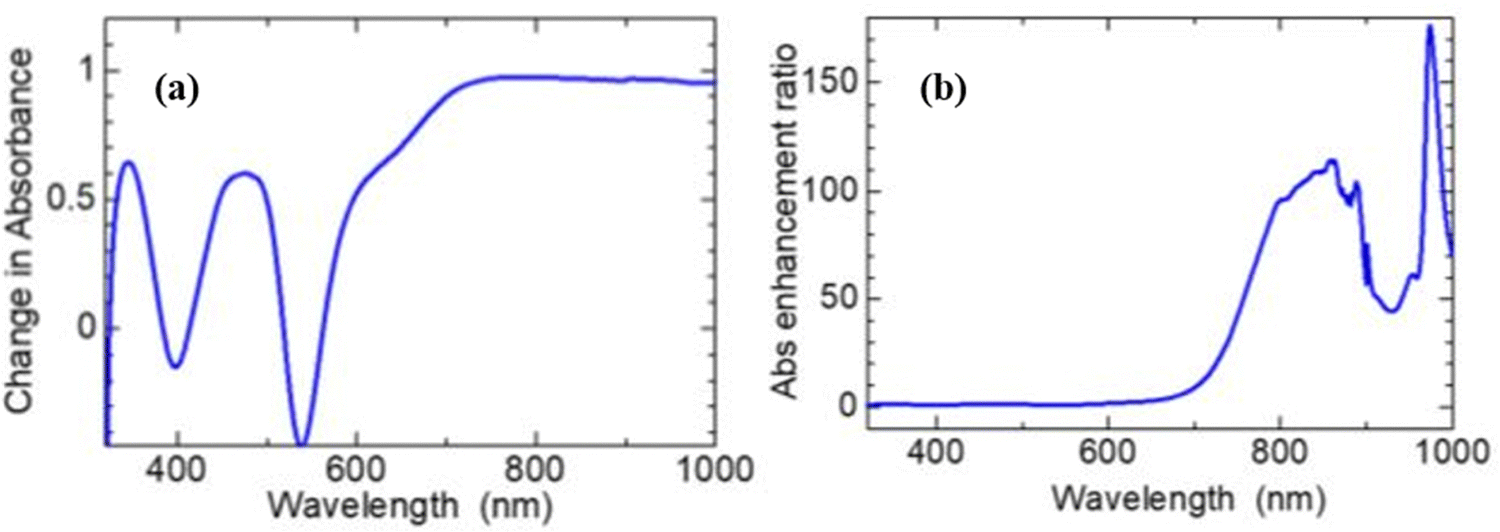 | ||
| Fig. 20 Optical absorption spectra showing enhanced broadband light absorbance of the N719 dye: (a) absorbance of [0.12 mg ml−1 dye] – absorbance of [dye-only]. (b) The absorbance of [0.12 mg ml−1 dye] ÷absorbance of [dye-only].176 | ||
An optimal concentration of Ag aids in enhancing the short circuit current density and reducing in Voc, which is attributed to the optimal lowering of the Fermi level of the photoanode and efficient electron injection. Optimal doping concentration is necessary to balance the positive and negative effects of plasmonic doping. The advantages are improved charge transport and lower recombination owing to the electron-sink effect. The disadvantage is poor charge injection efficiency due to increasing Fermi levels.
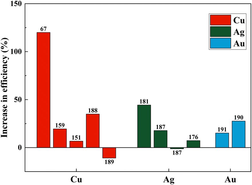
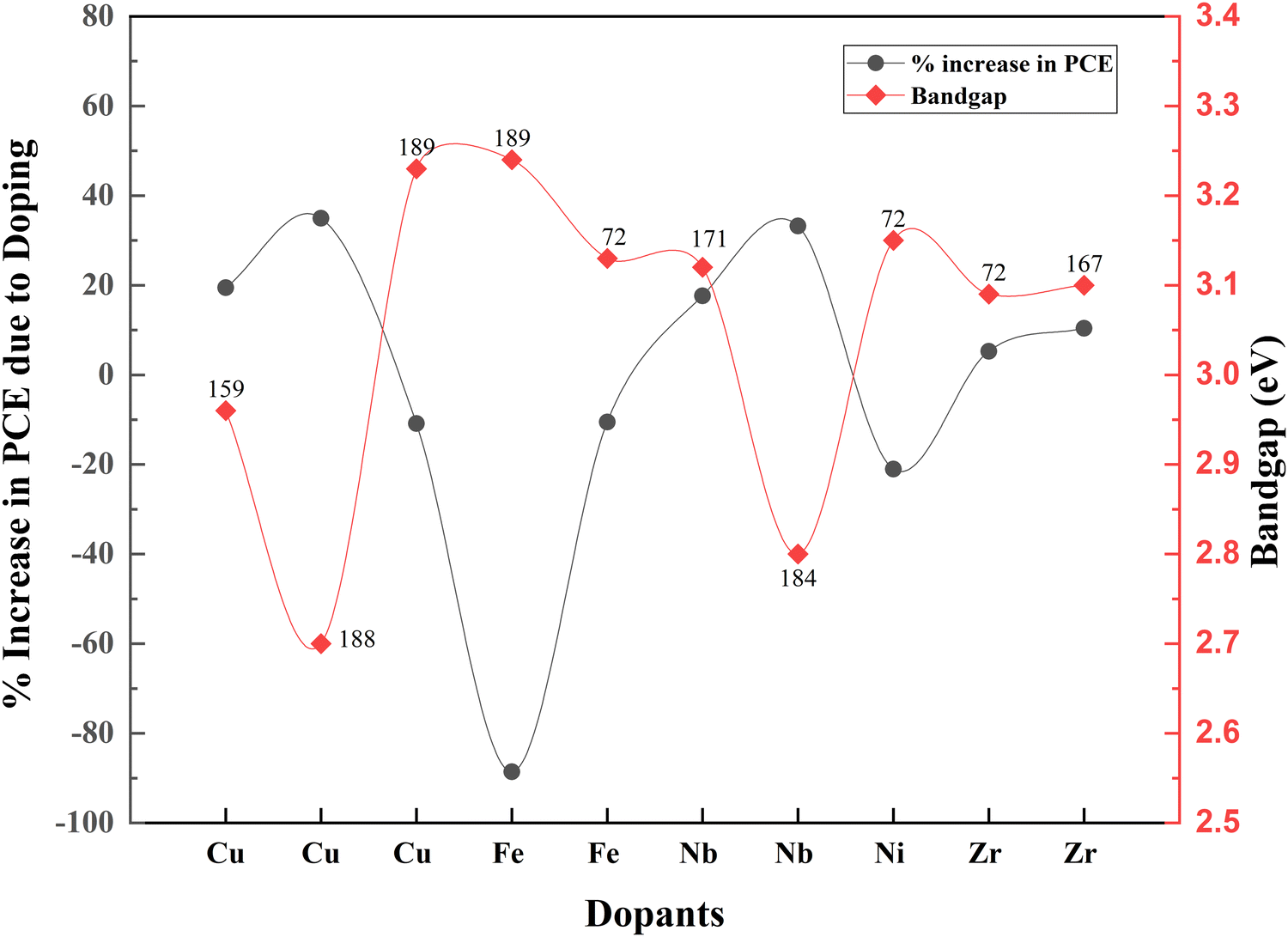
Fig. 21(a)–(c) and Table 3 summarize the performance of dopants which increased the efficiency by more than ten percent. However, dopants that increased the PCE by less than 10% are also included in Table 1. As seen in Fig. 21, copper, zinc, and zirconium increased the efficiency drastically when doped.67,74,180 However, Ag, Cr, Nb, Ta, W, and Y showed an increase in PCE (locked below 50%).146,166,181–184 At the same time, in a different study, the highest-performing zirconium and copper showed a decrease in PCE.154,185,186 Other than these, Ag, Fe, Ni, Mn, and Co also reduced the efficiency of DSSCs compared to the control DSSC when doped into a TiO2 photoanode.72,135,187
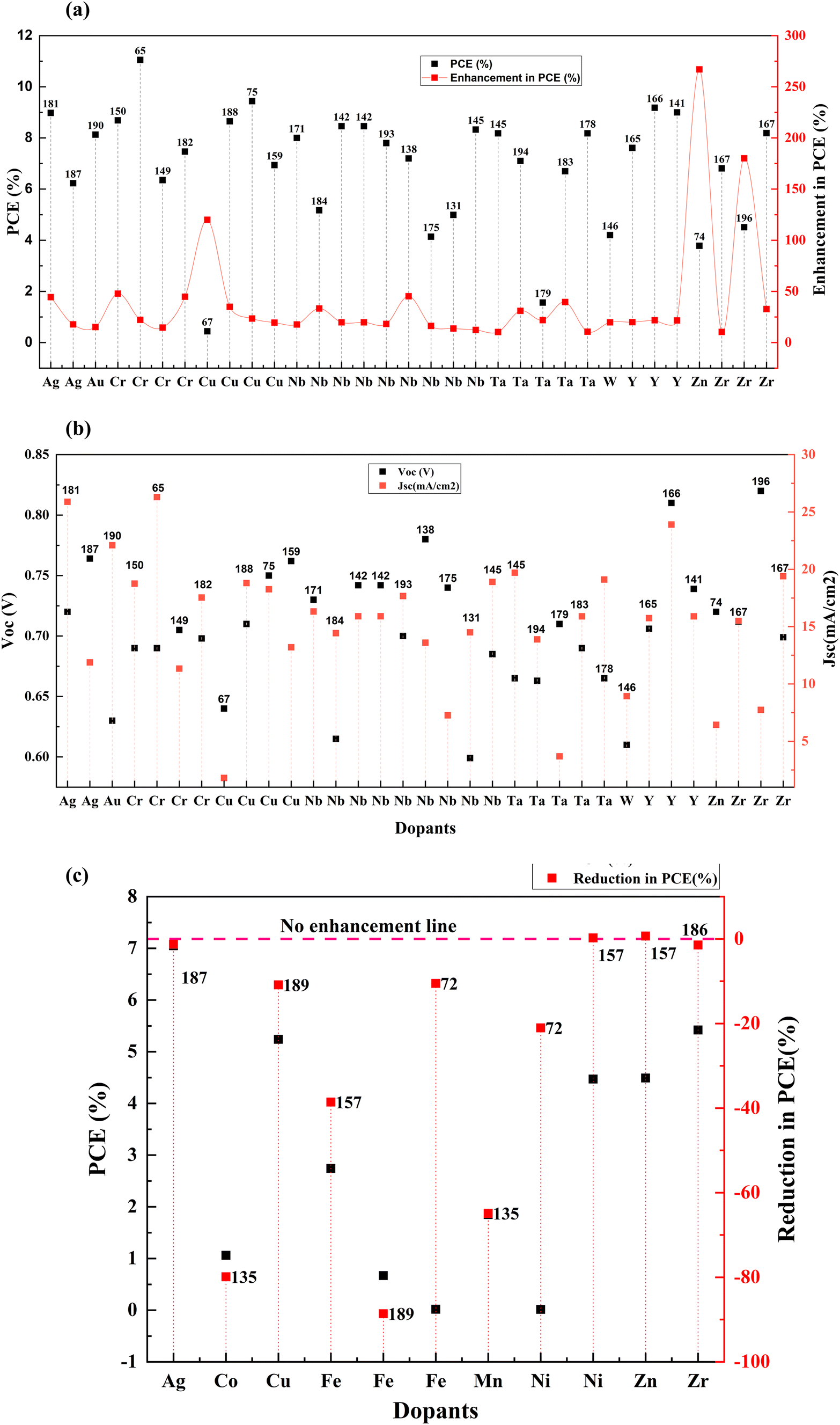 | ||
| Fig. 21 (a) Performance of transition metals when doped into TiO2 for DSSC fabrication. (b) Jsc and Voc of transition metals when doped into TiO2 for DSSC fabrication. (c) Reduction in PCE when transition elements are doped into TiO2 for DSSC fabrication. Data points are labelled with references. | ||
| S. no. | Dopant | Treatment/coating | Structure | Synthesis method | V oc (V) | Photocurrent density (mA cm−2) | FF | PCE (%) | Enhancement in PCE (%) | Bandgap (eV) | Application | Sensitizer/dye | Ref. |
|---|---|---|---|---|---|---|---|---|---|---|---|---|---|
| 1 | Chromium (Cr) | Nanoparticles | Hydrothermal and doctor blade | 0.705 | 11.34 | 0.69 | 6.35 | 14.62 | DSSC | N719 | 149 | ||
| 2 | Chromium (Cr) | Bilayers, NPs, nanotubes | Microwave assisted hydrothermal | 0.69 | 18.75 | 0.66 | 8.69 | 47.79 | DSSC | N719 | 150 | ||
| 3 | Chromium (Cr) | Nanoparticles, nanotubes | Microwave assisted hydrothermal | 0.69 | 26.29 | 0.6 | 11.05 | 22.10 | DSSC | N719 | 65 | ||
| 4 | Chromium (Cr) | Nanoparticles, nanotubes | Sol–gel, spin coating | 6.98 | 17.54 | 0.609 | 7.47 | 44.77 | DSSC | N719 | 182 | ||
| 5 | Cobalt (Co) | Nanoparticles | Hydrothermal, doctor blade | 0.6 | 3.12 | 0.571 | 1.06 | −79.89 | DSSC | N719 | 135 | ||
| 6 | Cobalt (Co) | Nanoparticles | Microwave assisted hydrothermal | 1.201 | 6.87 | 0.59 | 4.85 | 8.74 | DSSC | N719 | 157 | ||
| 7 | Cobalt (Co) | Brookite | Spray pyrolysis | 0.87 | 11.04 | 0.59 | 5.66 | 3.3 | DSSC | N719 | 156 | ||
| 8 | Copper (Cu) | Core–shell nanostructures, nanowires | Doctor blade | 0.75 | 18.26 | 0.68 | 9.44 | 23.40 | DSSC | N719 | 75 | ||
| 9 | Copper (Cu) | Nanowalls | Liquid phase deposition | 0.64 | 1.8 | 0.0038 | 0.44 | 120.00 | 3.32 | DSSC | N719 | 67 | |
| 10 | Copper (Cu) | Nanoparticles | Microwave assisted hydrothermal | 0.762 | 13.2 | 0.689 | 6.94 | 19.45 | 2.96 | DSSC | N719 | 159 | |
| 11 | Copper (Cu) | Nanoparticles | Microwave assisted hydrothermal | 1.073 | 7.34 | 0.65 | 5.09 | 6.71 | DSSC | N719 | 151 | ||
| 12 | Copper (Cu) | Nanoparticles | Sol–gel | 0.71 | 18.8 | 0.642 | 8.65 | 34.95 | 2.7 | DSSC | N719 | 188 | |
| 13 | Copper (Cu) | Nanoparticles | Sol–gel, hydrothermal | 0.76 | 10.68 | 0.585 | 5.24 | −10.88 | 3.23 | DSSC | N719 | 189 | |
| 14 | Gold (Au) | Thin shell, hollow sub-microspheres | Hydrothermal | 0.63 | 22.1 | 0.64 | 8.13 | 15.16 | DSSC | N719 | 190 | ||
| 15 | Gold (Au) | Nanoparticles | 0.7 | 0.7 | 0.5611 | 6.51 | DSSC | N719 | 191 | ||||
| 16 | Iron (Fe) | Nanoparticles | Microwave assisted hydrothermal | 0.939 | 8.37 | 0.35 | 2.74 | −38.57 | DSSC | N719 | 157 | ||
| 17 | Iron (Fe) | Nanoparticles | Sol–gel | 0.29 | 0.22 | 0.0027 | 0.017 | −10.53 | 3.13 | DSSC | N719 | 72 | |
| 18 | Iron (Fe) | Nanoparticles | Sol–gel, hydrothermal | 0.71 | 1.14 | 0.731 | 0.67 | −88.61 | 3.24 | DSSC | N719 | 189 | |
| 19 | Manganese (Mn) | Nanoparticles | Hydrothermal, doctor blade | 0.656 | 4.241 | 0.667 | 1.85 | −64.90 | DSSC | N719 | 135 | ||
| 20 | Manganese (Mn) | Nanoparticles | Microwave assisted hydrothermal | 1.181 | 7.52 | 0.55 | 4.87 | 2.10 | DSSC | N719 | 151 | ||
| 21 | Nickel (Ni) | Nanoparticles | Microwave assisted hydrothermal | 1.126 | 7.75 | 0.51 | 4.47 | 0.22 | DSSC | N719 | 157 | ||
| 22 | Nickel (Ni) | Nanoparticles | Sol–gel | 0.31 | 0.17 | 0.0029 | 0.015 | −21.05 | 3.15 | DSSC | N719 | 72 | |
| 23 | Niobium (Nb) | Nanorods | Electrochemical anodization | 0.615 | 14.43 | 0.583 | 5.17 | 33.25 | 2.8 | DSSC | N719 | 184 | |
| 24 | Niobium (Nb) | Nanoparticles | Horizontal ultrasonic spray pyrolysis deposition (HUSPD) | 0.74 | 16.9 | 0.6026 | 7.5 | 4.75 | DSSC | N719 | 192 | ||
| 25 | Niobium (Nb) | Nanoparticles | Hydrothermal | 0.7 | 17.67 | 0.63 | 7.8 | 18.18 | DSSC | N719 | 193 | ||
| 26 | Niobium (Nb) | Nanoparticles | Hydrothermal | 0.742 | 15.907 | 0.717 | 8.459 | 19.78 | DSSC | N719 | 142 | ||
| 27 | Niobium (Nb) | Nanoparticles | Hydrothermal | 0.685 | 18.9 | 0.64 | 8.33 | 12.26 | DSSC | N3 | 145 | ||
| 28 | Niobium (Nb) | Porous microspheres | Hydrothermal method followed by heat treatment | 0.599 | 14.5 | 0.575 | 4.99 | 13.67 | DSSC | N719 | 131 | ||
| 29 | Niobium (Nb) | Nanoparticles | Hydrothermal synthesis and screen printing | 0.742 | 15.907 | 0.717 | 8.459 | 19.78 | DSSC | N719 | 142 | ||
| 30 | Niobium (Nb) | Nanoparticles | Screen printing | 0.74 | 7.26 | 0.76 | 4.14 | 16.29 | DSSC | N719 | 175 | ||
| 31 | Niobium (Nb) | Nanoparticles | Sol–gel, co-hydrolysis, hydrothermal treatment | 0.73 | 16.32 | 0.68 | 8 | 17.65 | 3.12 | DSSC | N719 | 171 | |
| 32 | Niobium (Nb) | Nanoarrays, nanoparticles | Two-step hydrothermal, spin-coating approach | 0.78 | 13.6 | 0.68 | 7.2 | 45.16 | DSSC | N719 | 138 | ||
| 33 | Scandium (Sc) | Mesoporous beads/nanoparticles | Controlled hydrolysis | 0.752 | 19.1 | 0.675 | 9.6 | 6.67 | DSSC | N719 | 127 | ||
| 34 | Silver (Ag) | 3D flower like microstructures | Hydrothermal, photoreduction | 0.72 | 25.88 | 0.49 | 8.98 | 44.37 | DSSC | N719 | 181 | ||
| 35 | Silver (Ag) | Nanoparticles | Polyol, electrospinning | 0.764 | 11.88 | 0.685 | 6.23 | 17.77 | DSSC | N719 | 187 | ||
| 36 | Silver (Ag) | Nanoparticles, nanofibres | Polyol, electrospinning | 0.752 | 13.68 | 0.685 | 7.05 | −1.26 | DSSC | N719 | 187 | ||
| 37 | Silver (Ag) | Nanoparticles | Sol process | 0.744 | 8.93 | 0.591 | 5 | 7.30 | DSSC | N719 | 176 | ||
| 38 | Silver (Ag) | Ag coating | Nanoparticles | 0.71 | 4.24 | 0.62 | DSSC | N719 | 177 | ||||
| 39 | Tantalum (Ta) | Nanoparticles | Atomic layer deposition | 0.71 | 3.69 | 0.6 | 1.56 | 21.88 | DSSC | N719 | 179 | ||
| 40 | Tantalum (Ta) | Nanoparticles | Hydrothermal | 0.665 | 19.7 | 0.65 | 8.18 | 10.24 | DSSC | N3 | 145 | ||
| 41 | Tantalum (Ta) | Nanoparticles | Hydrothermal | 0.665 | 19.1 | 0.65 | 8.18 | 10.54 | DSSC | N3 | 178 | ||
| 42 | Tantalum (Ta) | Nanoparticles | Laser ablation | 0.69 | 15.9 | 0.61 | 6.7 | 39.58 | DSSC | N719 | 183 | ||
| 43 | Tantalum (Ta) | Nano spheres | Screen printing method | 0.663 | 13.89 | 0.77 | 7.1 | 31.00 | DSSC | N719 | 194 | ||
| 44 | Tungsten (W) | Nanoparticles | Modified sol–gel | 0.61 | 8.94 | 0.77 | 4.2 | 19.76 | DSSC | A new coumarin dye | 146 | ||
| 45 | Vanadium (V) | Nanoparticles | Hydrothermal | 0.687 | 17.6 | 0.65 | 7.8 | 5.12 | DSSC | N3 | 145 | ||
| 46 | Yttrium (Y) | Nanoparticles | Gel–sol | 0.706 | 15.74 | 0.6846 | 7.61 | 19.97 | DSSC | N719 | 165 | ||
| 47 | Yttrium (Y) | Nanoparticles | Hydrothermal | 0.739 | 15.9 | 0.77 | 9 | 21.62 | DSSC, QDSSC | C101 Ru(+II) | 141 | ||
| 48 | Yttrium (Y) | Nanoparticles | Hydrothermal | 0.81 | 23.9 | 0.4724 | 9.18 | 21.79 | DSSC | N719 | 166 | ||
| 49 | Zinc (Zn) | Nanowalls | Liquid phase deposition | 0.66 | 10.68 | 0.28 | 1.98 | DSSC | N719 | 195 | |||
| 50 | Zinc (Zn) | Nanoparticles | Microwave assisted hydrothermal | 1.097 | 7.85 | 0.52 | 4.49 | 0.67 | DSSC | N719 | 157 | ||
| 51 | Zinc (Zn), cobalt (Co) | Sol–gel | 0.72 | 6.44 | 0.82 | 3.78 | 266.99 | 2.9 | DSSC | N719 | 74 | ||
| 52 | Zirconium (Zr) | Ball milling, dissolving, impregnation, mixing, screen printing | 0.7067 | 10.527 | 0.75 | 5.42 | −1.45 | DSSC | N719 | 186 | |||
| 53 | Zirconium (Zr) | Nanoparticles | Sol–gel | 0.712 | 15.5 | 0.626 | 6.81 | 10.37 | 3.1 | DSSC | N719 | 167 | |
| 54 | Zirconium (Zr) | CNT coating | Nanoparticles | Sol–gel | 0.699 | 19.4 | 0.602 | 8.19 | 32.74 | DSSC | N719 | 167 | |
| 55 | Zirconium (Zr) | Nanoparticles | Sol–gel | 0.45 | 0.13 | 0.0034 | 0.02 | 5.26 | 3.09 | DSSC | N719 | 72 | |
| 56 | Zirconium (Zr) | Nanofibers | Sol–gel, electrospinning | 0.82 | 7.74 | 0.71 | 4.51 | 180.12 | 3.22 | DSSC | N719 | 196 |
Even though doping research is thriving, associated bandgap data are relatively less noted. Fig. 22 shows the variation of bandgap and the corresponding effect on PCE with doping. When the bandgap is reduced, there is an increase in PCE and vice versa. Nevertheless, TiO2 nanofiber does not follow this order. When the bandgap is higher, the PCE increases.
 | ||
| Fig. 22 Bandgap and increase in PCE with doping in transition elements. Data points are labelled with references. | ||
3.6. Post-transition metals
Post-transition metals are poor metals with lower reactivity. They are also brittle and generally have low boiling points than transition metals. These include aluminum, gallium, indium, tin, thallium, lead, and bismuth. Except for thallium and lead, all other post-transition metals were doped into TiO2 to increase conductivity, change the absorption to the visible region for better charge-hole separation, decrease the recombination, and tailor the surface defects for better charge transfer by changing dimensionality.81,197–201These traps effectively reduce the photocurrent through charge recombination. However, aluminum doping has a positive effect on DSSCs despite the drop in the photocurrent.202 Not just in DSSCs, Al3+ doped TiO2 has a positive influence on PCE when used as an electrode material in QDSSCs. But the study by R. Li et al. published in 2016 showed that doping aluminium into the mesoporous TiO2 followed by 500 °C sintering increased the PCE significantly over the other two studies in 2011202 and 2017.71 Aluminum doping into the mesoporous layer increased the PCE by around 67 percent. The incorporation of Al ions into the TiO2 causes a change in the concentration of defect states. The flat band potential plays a vital role by increasing the electron injection rate and charge collection efficiency. Altogether, they contributed to the efficiency in the DSSC. Even though the efficiency is much lower in the study by R. Li et al., the effect of aluminum doping stands out.
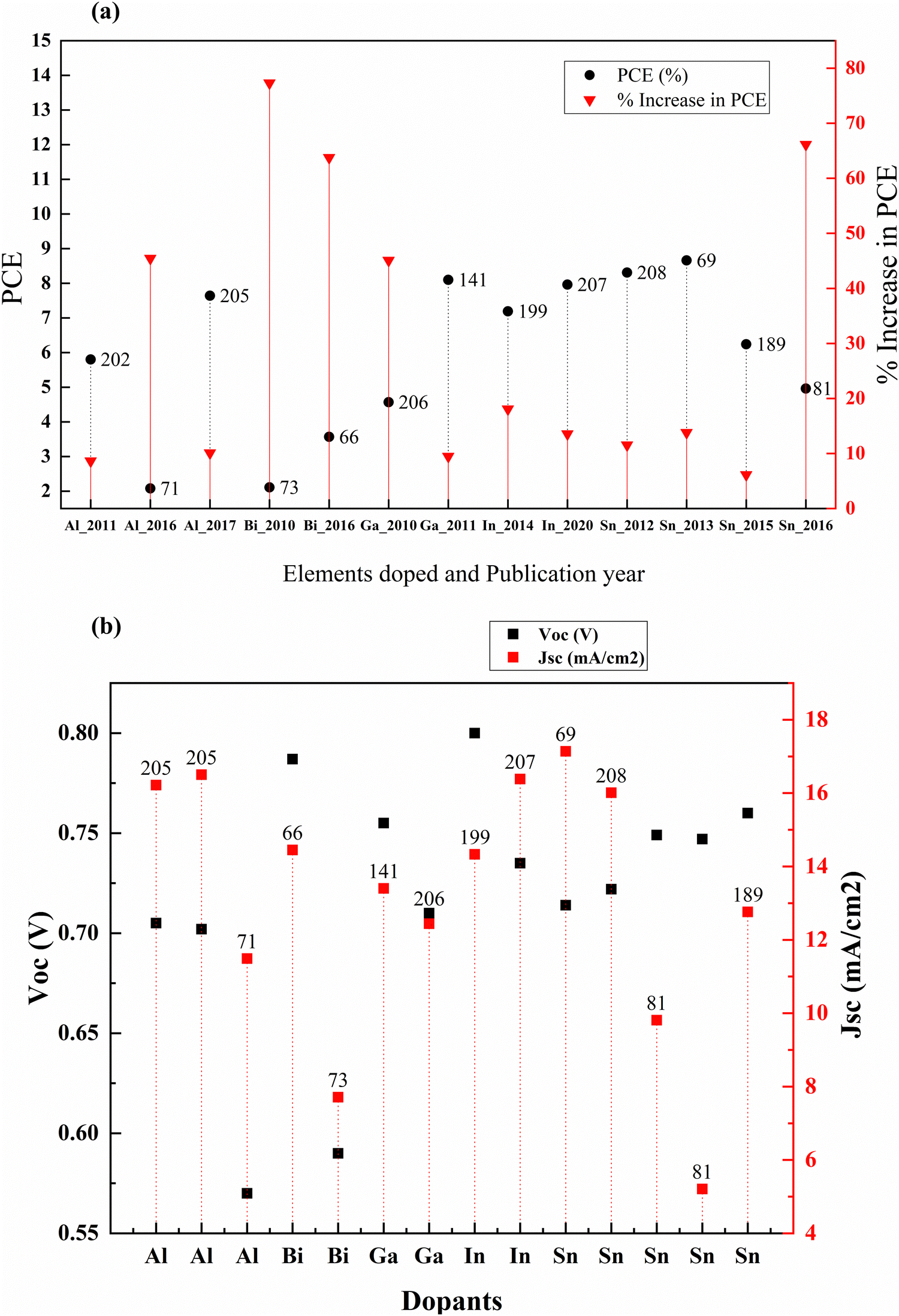 | ||
| Fig. 23 (a) Percentage increase in PCE in post-transition metals with doping. (b) Jsc and Voc of post-transition metals when doped into TiO2 for DSSC fabrication. Data points are labelled with references. | ||
| S. no. | Dopant | Treatment/coating | Structure | Synthesis method | V oc (V) | Photocurrent density (mA cm−2) | FF | PCE (%) | Enhancement in PCE (%) | Bandgap (eV) | Application | Sensitizer/dye | Ref. |
|---|---|---|---|---|---|---|---|---|---|---|---|---|---|
| 37 | Aluminium (Al) | Mesoporous | Chemical bath deposition | 0.705 | 16.22 | 0.6677 | 7.64 | 10.09 | DSSC | N719 | 205 | ||
| 38 | Aluminium (Al) | Nanoparticles | Doctor blade | 0.702 | 16.5 | 65.75 | 7.66 | 9.12 | DSSC | N719 | 205 | ||
| 39 | Aluminium (Al) | Nanoparticles | Screen printing | 0.57 | 11.49 | 0.318 | 2.08 | 45.45 | QDSSC | CdS/ZnS | 71 | ||
| 40 | Bismuth (Bi) | Nanofibres | Hydrothermal | 0.787 | 14.45 | 78.2 | 3.57 | 63.76 | DSSC | N719 | 66 | ||
| 41 | Bismuth (Bi) | Nanocubes | Sol–gel hydrothermal | 0.59 | 7.71 | 0.46 | 2.11 | 77.31 | DSSC | N3 | 73 | ||
| 42 | Gallium (Ga) | Nanoparticles | Hydrothermal | 0.755 | 13.4 | 0.79 | 8.1 | 9.46 | DSSC, QDSSC | C101 Ru(+II) | 141 | ||
| 43 | Gallium (Ga) | Nanoparticles | Hydrothermal | 0.71 | 12.44 | 0.51 | 4.57 | 45.08 | DSSC | N3 | 206 | ||
| 44 | Indium (In) | Nanoparticles | Simple surface doping technique by immersing TiO2 films with In3+ acidic solution at different soaking times at 70 °C followed by sintering at 450 °C | 0.8 | 14.33 | 0.63 | 7.19 | 18.06 | DSSC | C264 triphenylamine dye | 199 | ||
| 45 | Indium (In) | Nanoparticles | Sol–gel, spin coating | 0.735 | 16.384 | 0.661 | 7.96 | 13.55 | DSSC | N719 | 207 | ||
| 46 | Tin (Sn) | Nanoparticles | Hydrothermal | 0.714 | 17.14 | 0.71 | 8.66 | 13.80 | DSSC | N3 | 69 | ||
| 47 | Tin (Sn) | Hydrothermal | 0.722 | 16.01 | 0.707 | 8.31 | 11.54 | DSSC | N3 | 208 | |||
| 48 | Tin (Sn) | Post-treated with Zr and HNO3 | Nanorods | Sol–gel, hydrothermal | 0.749 | 9.81 | 0.674 | 4.96 | 2.99 | DSSC | N719 | 81 | |
| 49 | Tin (Sn) | Post-treated with Zr and HNO4 | Nanorods | Sol–gel, hydrothermal | 0.747 | 5.21 | 0.534 | 2.09 | 2.99 | DSSC | Leaves of Camellia sinensis | 81 | |
| 50 | Tin (Sn) | Nanoparticles | Sol–gel, hydrothermal | 0.76 | 12.76 | 0.577 | 6.24 | 6.12 | 3.27 | DSSC | N719 | 189 |
(1) Direct transfer from the conduction band to electrolyte.
(2) Indirect transfer from monoenergetic deep surface states.
(3) Indirect transfer from the distribution of bandgap surface states.
In the indium doping case, the surface trap states are dominant trap states and lead to decreased recombination centers, eventually benefiting the PCE.199
Analyzing PCE to understand doping is deceiving because it does not give any information about what it does to efficiency. Meanwhile, an increase in PCE provides vital information regarding the effect of doping. From the graph, it is clear that indium and tin have higher PCEs owing to their preparation methods. Aluminum, bismuth, and gallium when doped into TiO2 have significantly changed the DSSC's efficiency.
3.7. Halogens
Among halogens, fluorine and iodine showed effective narrowing of the bandgap attributed to their higher ability to absorb visible light. This observation is supported by DFT calculations of n-type iodine-TiO2 doping and p-type nitrogen-TiO2 doping. Comparatively, iodine doping improved the conductivity and increased the visible light absorption of anatase TiO2. From 2011 on, iodine and fluorine alternatively have become the best dopants for TiO2 from the halogen group. The statistical information about halogen doped TiO2 based DSSCs is summarized in Table 5.| S. no. | Dopant | Treatment/coating | Structure | Synthesis method | V oc (V) | Photocurrent density (mA cm−2) | FF | PCE (%) | Enhancement in PCE (%) | Bandgap (eV) | Application | Sensitizer/dye | Ref. |
|---|---|---|---|---|---|---|---|---|---|---|---|---|---|
| 1 | Fluorine (F) | Nanoparticles | Hydrolysis | 0.67 | 13.89 | 0.57 | 5.24 | 10.08 | DSSC | N719 | 218 | ||
| 2 | Fluorine (F) | Nanocuboids | Hydrothermal | 0.603 | 17.621 | 0.6984 | 7.463 | 62.45 | 3.1 | DSSC | N719 | 84 | |
| 3 | Fluorine (F) | Hollowspheres | Hydrothermal | 0.754 | 11 | 0.761 | 6.31 | DSSC | 215 | ||||
| 4 | Fluorine (F) | Quasi-cubic structures | Microwave assisted solvothermal | 0.745 | 18.74 | 0.59 | 8.2 | 63.35 | DSSC | N719 | 219 | ||
| 5 | Iodine (I) | Nanocrystals | Hydrolysis, hydrothermal | 0.715 | 14.1 | 0.67 | 7 | 42.86 | 2.4 | DSSC | N3 | 212 | |
| 6 | Iodine (I) | Spheres | Hydrothermal, screen printing | 0.616 | 13.81 | 0.75 | 6.38 | 34.03 | Quasi-solid state DSSC | N719 | 220 |
The idea of high-quality blocking layers that are non-metallic leads to the use of fluorine as a dopant for TiO2. Noh and coworkers introduced a new concept of dense layers into DSSCs for creating a non-ohmic layer between the nanoporous TiO2 layer and FTO glass. High interfacial resistance has hindered the efforts to develop adequate blocking layers. For example, Nb doping on the TiO2 dense layer increased the conductivity of the SrTiO3 substrate, but the thermal instability and production cost were high. Compared to the undoped samples, this work shows that the doping effect on DSSCs is substantially less.
Nevertheless, considering that this is one of the first works in fluorine-doped TiO2, this study used a low-cost method and materials for doping and successfully introduced a fluorine-doped dense layer. This layer prevented back electron transfer, a breakthrough in DSSC research.216 Fluorine (F−) is a superior anionic dopant due to its high electronegativity. It disrupts the CB and inhibits electron recombination by its strong electronegativity. Fluorine ions can penetrate the lattice and induce Ti3+ species generation, which helps in charge collection efficiency. Fig. 24 shows that the fluorine content increases in the TiO2 electrode and the bandgap increases. Consequently, the efficiency of the DSSC increases. On the optimal doping we discuss throughout this paper, at 6% doping, the F-doped TiO2-based DSSC reaches maximum efficiency. Beyond this doping point, fluorine doping adversely affects the DSSC's efficiency. F-doped TiO2 nanocubes with a nanovoid/pore morphology play a crucial role in confining light and favoring electron transfer. Nanocubes increase the surface area, thus enhancing dye loading and light trapping. These naturally result in the percentage improvement in the efficiency of the F-doped TiO2 based DSSC compared to the bare TiO2-based DSSC. The presence of nanovoids at the surface of TiO2 influences the grain boundary resistance by increasing the electron concentration. Consequently, this leads to an increase in charge transportation rate. However, the F-doping concentration increases with space charge polarization effects due to intensive charge carriers, resulting in more recombination.217
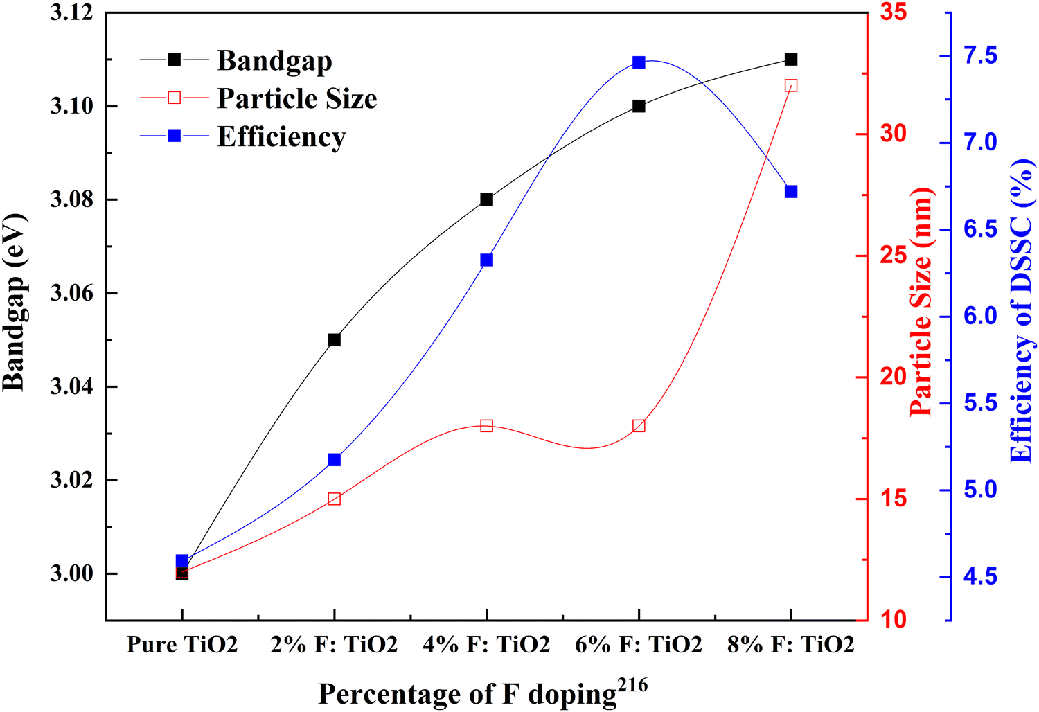 | ||
| Fig. 24 Correlation of the percentage of F doping with bandgap, particle size and efficiency. | ||
Defects generated by mesoporous TiO2 result in numerous electronic sub-bandgap trap states.221 Peng Xiang et al. doped TiO2 with iodine and applied it in a quasi-solid state DSSC. From Fig. 25(a), it is clear that iodine doping is vital in improving the cell performance by 34 percent, owing to the distributed pores, which increase the surface area. Nevertheless, compared to fluorine, the percentage efficiency improvement achieved is insignificant in this study.222Fig. 25(b) provides the comparison of Voc and Jsc data of halogen doped TiO2 based DSSCs. Recently, microwave-assisted solvothermal doping of fluorine into TiO2 was explored. This preparation method is very competitive with all other fluorine doping techniques. Compared to other methods, this method is non-toxic and non-corrosive as well. In this study, F-doped TiO2 forms a quasi-cubic morphology due to the fluorine iron doping. F doping introduces mesoporous structures. The ability of fluorine to separate charges is crucial in DSSC efficiency. Fluorine doping also induces facets that have high surface energy and lead to the formation of heterojunctions. This improves the photogenerated carrier density. The high adsorption capacity of fluorine creates Ti–F and Ti–F–Ti bonding by replacing oxygen. This action favors charge separation.83
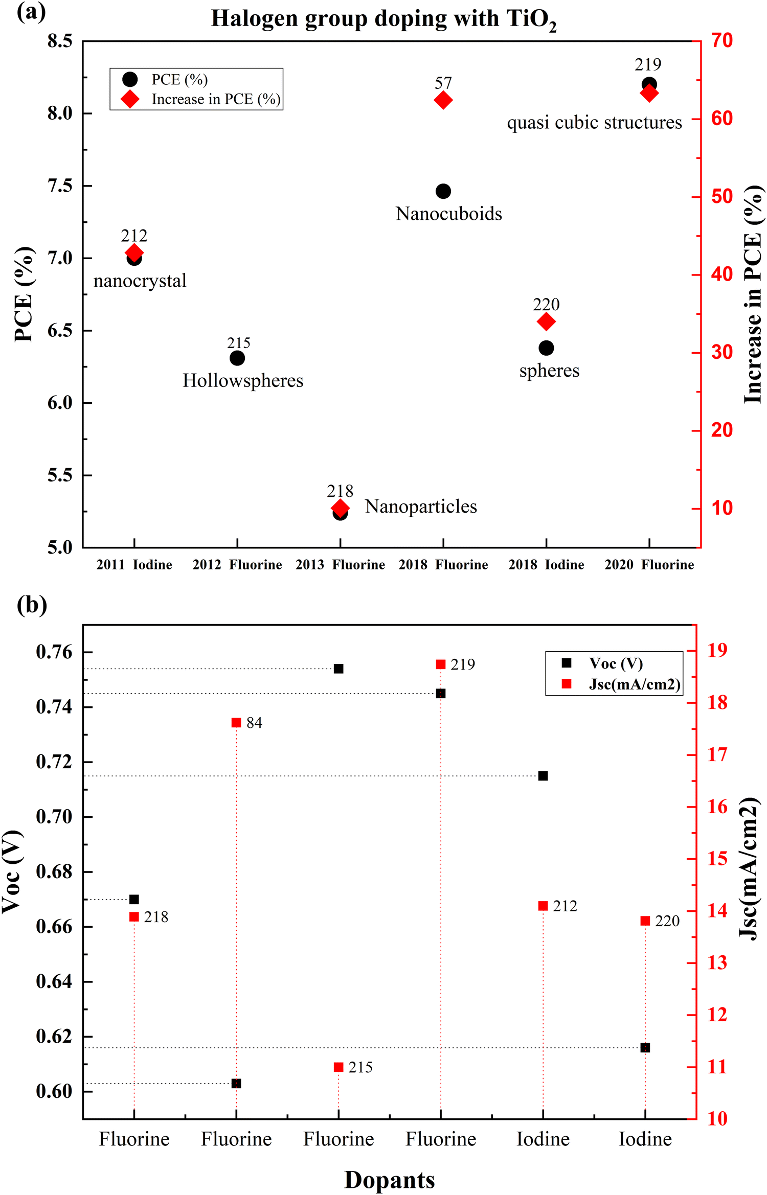 | ||
| Fig. 25 (a) Comparison of the PCEs of different halogen doped TiO2 based DSSCs from 2011. (b) Jsc and Voc of halogen doped TiO2 based DSSCs. Data points are labelled with references. | ||
Since 2011, halogen group elements have been used as prospective candidates for improving the conductivity of photoanodes for DSSCs. Researchers successfully doped TiO2 into blocking layers into various TiO2 structures such as hollow spheres, nanocuboids, and mesoporous structures. Since the introduction of hierarchical TiO2 layers and quasi-solid-state DSSCs, fluorine doping increases the conductivity, improves dye absorption, and quickens electron transport. Around 2020, researchers looked into the possibilities of non-corrosive, non-toxic, green synthesis routes and green precursor materials like polyvinylidene fluoride (PVDF).
3.8. Other nonmetals
Non-metal ions are thermally stable and suitable candidates for engineering the bandgaps by shifting the band edges compared with metal ionic dopants. Nitrogen is the most attractive non-metal for doping into TiO2 due to its comparable atomic size with oxygen. In 2009, Soon Hyung Kang and co-authors tried to enhance the DSSC photocurrent using a nitrogen-doped TiO2 anode. They incorporated urea into the sol–gel technique to obtain nitrogen-doped TiO2 for photovoltaic applications. Compared to the bare TiO2 samples, these samples were smaller in crystallite size. DSSCs fabricated with optimally doped samples exhibited an efficiency of 4.86%. Even though nitrogen is a frequent dopant, sulphur doped TiO2 was also used to prepare DSSCs for achieving better efficiencies.223,224 An increase in PCE of DSSCs when TiO2 is doped with all other non-metal elements is depicted in Fig. 26. Statistics of other nonmetal doped TiO2 based DSSCs are provided in Table 6.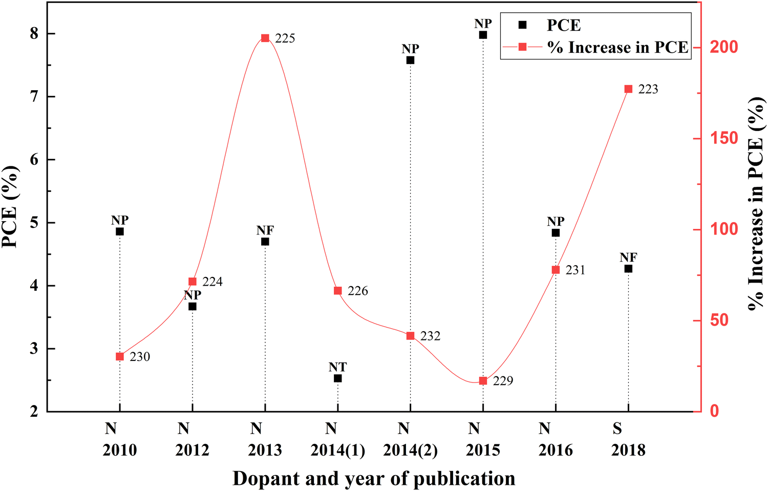 | ||
| Fig. 26 Increase in PCE with other nonmetal category dopants. Data points are labelled with references. | ||
| S. no. | Dopant | Treatment/coating | Structure | Synthesis method | V oc (V) | Photocurrent density (mA cm−2) | FF | PCE (%) | Enhancement in PCE (%) | Bandgap (eV) | Application | Sensitizer/dye | Ref. |
|---|---|---|---|---|---|---|---|---|---|---|---|---|---|
| 1 | Carbonate | Microspheres | Solvothermal | 0.76 | 16.6 | 0.625 | 7.65 | 48.26 | DSSC | N719 | 227 | ||
| 2 | Graphidyne (GD) | Nanoparticles | Homocoupling reaction, ball milling | 0.8 | 13.73 | 0.7434 | 8.03 | 20.92 | 2.89 | DSSC | N719 | 228 | |
| 3 | Nitrogen (N) | Nanoparticles | Doctor blade | 0.73 | 18.76 | 0.58 | 7.98 | 17.01 | DSSC | N719 | 229 | ||
| 4 | Nitrogen (N) | Nanofibres | Electrospinning process, hydrothermal treatment | 0.75 | 11.16 | 0.56 | 4.7 | 205.19 | DSSC | N719 | 225 | ||
| 5 | Nitrogen (N) | Nano spheres | Hydrothermal and doctor blade | 0.474 | 12.03 | 0.64 | 3.67 | 71.50 | QDSSC | CdSe | 224 | ||
| 6 | Nitrogen (N) | Nanoparticles | Sol–gel | 0.726 | 10.52 | 0.636 | 4.86 | 30.29 | DSSC | N719 | 230 | ||
| 7 | Nitrogen (N) | Nanotubes | Solvothermal | 0.67 | 8.82 | 0.4266 | 2.53 | 66.45 | DSSC | N719 | 226 | ||
| 8 | Nitrogen (N) | Nanoparticles | Wet chemical | 0.7426 | 9.52 | 0.6854 | 4.84 | 77.94 | 3.13 | DSSC | N719 | 231 | |
| 9 | Nitrogen (N) | Wet method, screen printing | 0.83 | 12.4 | 0.7362 | 7.58 | 41.68 | 3.15 | DSSC | N719 | 232 | ||
| 10 | Sulphur (S) | Nanofibers | Sol–gel, hydrothermal, electrospinning | 0.683 | 10.66 | 0.59 | 4.27 | 177.27 | DSSC | 223 |
Wang and his group incorporated 1D structures and nanoparticles and increased the efficiency percentage by 0.27 times that of a bare TiO2-based DSSC. Depositing nanoparticles in the walls of nanotubes is effective for increasing efficiency. These aligned nanotubes and dispersed nanoparticles provide a higher surface area. This anode material can be further modified using nitrogen doping. By limiting electron and hole recombination, elements doped into TiO2 can increase efficiency. Nitrogen-doped nanoparticles decorated with TiO2 were obtained by the solvothermal method. Small nanocrystals along the wall were confirmed with SEM and HRTEM. This modified structure was treated with Ti(OH)3, which was found to have a more significant influence on the morphology and photoelectric–chemical properties. The photoanode made with doped-nanoparticle-modified films showed improved light-harvesting efficiency. These nanoparticles that stuck on the nanotubes acted as light scattering centers, which reflected in the higher reflectivity. This Ti–O–N bonding, with nanotubes acting as vertical transport channels for photoinduced electrons and adsorbed nanoparticles together, increased the efficiency of DSSCs by 1.68 times the original efficiency.226 While the exact position of N remains debatable, Ti–O–N linkages point to the presence of N-ions in the TiO2 lattice by replacing the oxygen atom.
When the scattering layer came under the spotlight and became an essential part of DSSCs, doping and modifying the scattering layer attracted more comprehensive attention. Mixing nitrogen-doped aggregated sub-micron size particles into commercial TiO2, and using this as a scattering layer, increases the scattering percentage without any drawback in electrical properties. The IV characteristics of DSSCs with these mixed-phase scattering layers seem to be improved, and the efficiency is increased by 0.14 times that of the commercial scattering layer. Adding a scattering layer introduced the concept of multilayers to DSSC researchers. So, doping and introducing these multilayers into DSSCs has become the next challenge. Multilayers were introduced to increase the Jsc by adding the TiO2 layer (scattering, P25, Doped P25) into the FTO substrate. Using a compact layer, a P25 layer, and a N-doped TiO2 layer doubled the Jsc when compared with using an undoped TiO2 layer in the DSSC. However, this reduced the fill factor slightly and increased the efficiency. The charge transfer resistance of the TiO2/electrolyte interface is significantly less when a DSSC is prepared with N-doped samples. The resistance–efficiency relationship in these DSSC samples is commendably complex. When the TiO2 layers use P25, the charge transfer resistance is meager. When undoped TiO2 is replaced with P25 particles, nearly half of the original charge transfer resistance is increased. Even though doped multilayers considerably improved the solar performance of DSSCs, when N-doped layers are used in place of undoped TiO2, the charge transfer resistance, ion diffusion resistance, and shunt resistance simultaneously decreased.229
In general, nitrogen induces a redshift in the absorption band edge due to the positive shift in flat band potential of TiO2.233–239 Incorporation of N3− into the TiO2 lattice can cause replacement of Ti4+ and fill up interstitial sites. Even when there is a higher Jsc due to increased dye absorption and improved electron injection, charge transport can be affected by lattice distortion.239,240 However, most studies agree with increased charge transport rates and reduced carrier recombination.226,241–244
4. Co-doping
The light absorption, charge transport, and charge transfer characteristics of an anode determine the efficiency of an electrochemical cell. Successful doping of suitable elements into TiO2 improves these fundamental properties. However, single elemental doping is inadequate to satisfy the requirements of TiO2 as an anode material. These monodoped atoms act as recombination centers due to their partially occupied impurity-generated energy bands. Even though contradictory arguments and theoretical calculations exist against passivation theory, many researchers are still on board with passivation theory.248 Investigations by Dhonde et al. show that co-doping with more than one foreign atom can passivate or cause doping asymmetry to these impurity bands. In addition, co-doping effectively modulates the charge equilibrium.79 Consequently, co-doping increases the surface area and shifts the band edge in TiO2.82Alkaline earth metals, transition metals, post-transition metals, metalloids, and other non-metals investigated for codoping are marked in Fig. 27. Depending on the type of dopant, there are three types of strategies: metal–metal codoping, metal–nonmetal codoping, and nonmetal–nonmetal codoping.
 | ||
| Fig. 27 Elements explored for codoping into TiO2 for DSSC applications. | ||
4.1. Metal–metal codoping
Mono-metal dopants in TiO2 create serious recombination centers and deteriorate carrier transport. Metal atom doping of TiO2 causes the inhomogeneous distribution of dopants and requires high-temperature sintering, leading to particle agglomeration.249 Metal doping also causes rapid recombination of immobilized charge species and thermal instability of TiO2. However, it improves band structure and shifts absorption towards a longer wavelength. Codoping focuses on increasing Voc and Jsc simultaneously through the synergetic effect of dopants. The metal dopant combinations are Al–La, Ca–La, Eu–Tb, Mg–La, Ni–Zn, Nb–Fe, Sr–V, Sr–Cr, Zn–Mg, and Zn–Ga. Fig. 28 shows the effects of these metal codoped TiO2 based DSSC efficiency enhancements.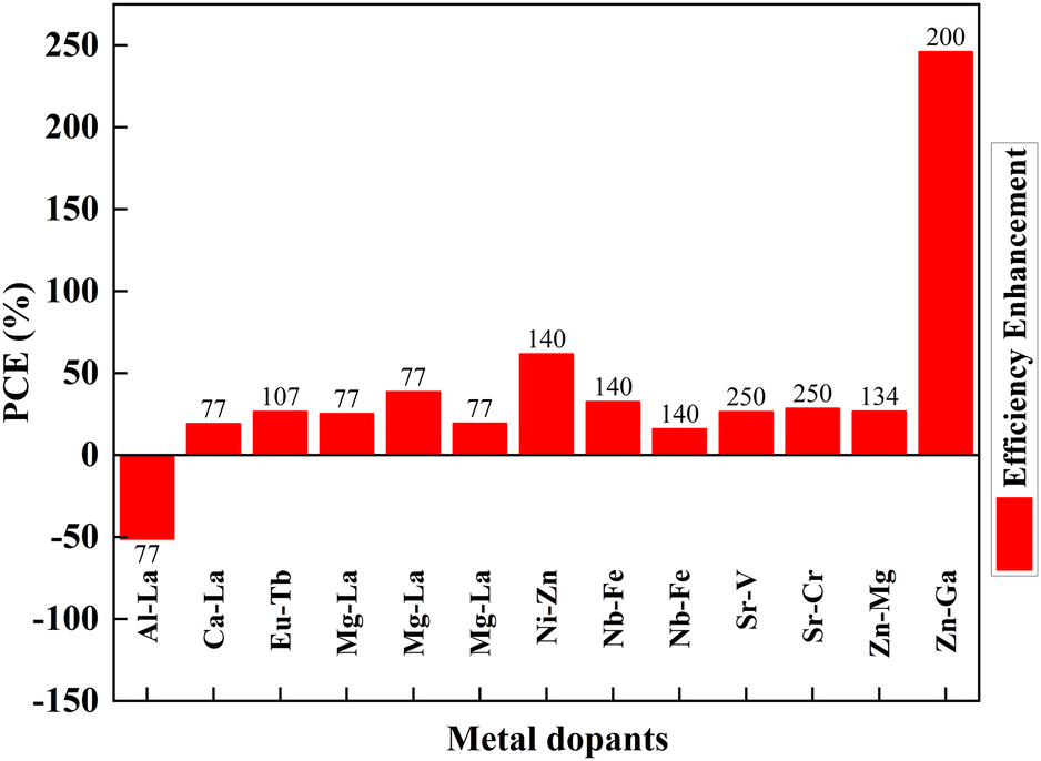 | ||
| Fig. 28 Effects of metal-doped TiO2 in the efficiency profile of DSSCs. Data points are labelled with references. | ||
Amid metal dopants, Zn–Ga combinational doping into TiO2 exhibits the highest efficiency in DSSCs. Changes in the electronic structure of TiO2 facilitate oxygen ion movement in the lattice, superior crystallization, and lattice expansion. During doping, Zn2+ and Ga3+ move into the lattice, facilitating the breaking and formation of new bonds. Zinc, an n-type dopant, causes a shift in Fermi level towards the conduction band, leading to an increase in the redox potential of electrolyte and a consequent increase in open-circuit voltage. Furthermore, the trap state distribution in TiO2 has been reduced through zinc doping and has abetted the increase in short circuit current.200
A high concentration of trap sites reduced electron transport and formed an impurity-grazed bandgap in Al–La-doped TiO2. Furthermore, insertion of Al3+ ions into the TiO2 lattice increased the recombination rate and resulted in inefficiency. In Mg–La, Mg–Ca, and Mg–Al doping, the ionic radius plays a vital role in solar cell efficiency. Titanium has smaller ionic radii than La3+, Mg2+, and Ca2+. While doping, these atoms cannot penetrate the lattice. However, Al3+ quickly enters the lattice without further problems. Prominent ions, Ca2+ and La3+, cannot penetrate the TiO2 lattice after doping.77
Consequently, these bigger atoms remain on the surface, facilitating better charge transfer. Relative to these systems, an Al–La codoped system has inefficient charge transfer resulting in low cell efficiency. Mg2+ ions are slightly larger than Ti4+ ions. During doping, Mg2+ enters the lattice and causes slight distortions in the parent material lattice. Moreover, while larger atoms induce surface charge trapping, Mg2+ doping provides deep charge trapping in the materials. However, Mg2+ ion substitution substitutes Ti4+, resulting in band edge shift.77
Ni–Zn doping into TiO2 achieves more than a 50 percent increase in efficiency than the undoped material. This achievement requires tricky bandgap engineering. Ni produces a negative shift, and Zn causes a positive shift in flat band potential. Consequently, Ni increases the open-circuit voltage and reduces the short-circuit current. It is vice versa for Zn. Ni–Zn doping mainly shifts the fundamental absorption edge and reduces the band energy. However, finding the optimum point for the maximum Voc and Jsc is challenging. Nb–Fe doping shifts the conduction band edge. Subsequently, the absorption changes from UV to visible light. Fe and Nb dopants serve as trap states and increase the electron lifetime via trapping and de-trapping events over trapping sites of Ti3+, Nb5+and Fe3+. Another research study on the same dopants suggests that Fe and Nb at ultralow concentrations generate Ti3+ donor trap states. These trap sites facilitate efficient charge diffusion and collection in titania nanobelts.140
Sr,V codoped TiO2 shows lower electron transit time, higher electron diffusion, and lower resistance, aiding efficiency. The increased charge separation and electron transformation demonstrated through EIS analysis confirm the doped sample's improved efficiency. The synergistic effect of Sr and Cr doping is vital for increasing efficiency. Cr incorporation into the TiO2 lattice produces isolated energy levels adjacent to the conduction band, narrowing the band gap. Cr3+ has excess valence electrons, leading to the generation of holes near the valence band, further contributing to the reduction in the bandgap.250
When the crystallite size decreases, the efficiency increases in metal codoped TiO2. Except for the Zn–Ga sample, this observation concludes that large crystallites have an adverse effect on efficiency. Analysing the specific Zn–Ga doping instance, data shows that the DSSC generated with the sample having a crystallite size of around 19 nm has the highest efficiency, in line with the most recent studies. A detailed investigation shows that when the crystallite size increases more than 20 nm, a DSSC exhibits a drastic decrease in DSSC efficiency (Fig. 29). Optimum crystallite size plays a significant role even in the doping-related efficiency profile. The notable point is that doping affects crystallite size in general. An optimum doping amount exists for each dopant, which decreases the crystallite size to an optimum size. Further doping from this point consequently reduces the efficiency and increases agglomeration.
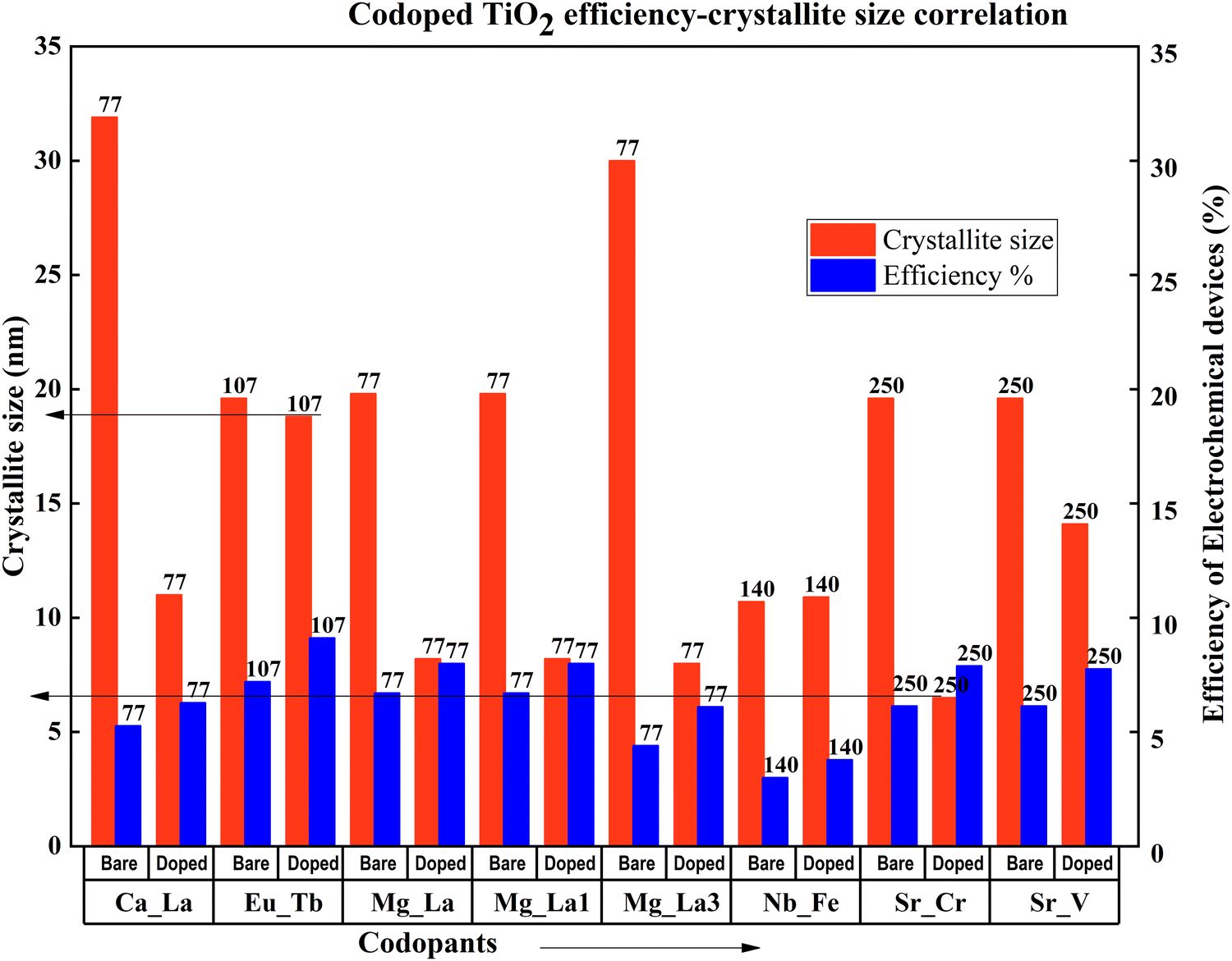 | ||
| Fig. 29 Codoped TiO2 efficiency–crystallite size correlation. Data points are labelled with references. | ||
All the doped TiO2 samples except for Zn–Ga and Nb–Fe doped samples have nanoparticle structures. Nb–Fe doped samples are in the form of nanobelts synthesized via a hydrothermal method. Zn–Ga has a thin-film structure prepared and fabricated by sol–gel and dip coating. These structural differences might have contributed to the efficiency increase in the Zn–Ga doped TiO2 sample. Compared with other sample preparation methods, the sol–gel technique is extensively used to prepare metal-codoped TiO2 samples. Doctor blade coating, screen printing, and dip coating are the fabrication methods used to prepare TiO2 anode materials for DSSCs.134
4.2. Metal–nonmetal codoping
The thermal instabilities of metal-doped TiO2 instigated the search for non-metal dopants for TiO2. Nitrogen, fluorine, sulfur, and boron are successful non-metal dopants. Doping with these non-metals alone brings changes in photocatalytic activity. However, the latest research indicates that codoping can further improve photocatalytic activity and promote the transportation of photogenerated electrons through the hybridization orbitals. Non-metal codoping is still a feeble area in doping TiO2. Yuanyuan and co-authors illustrated how doping increases the formation of the pure anatase phase rather than the rutile phase. A set of experiments with different concentrations of mesoporous N, S doped TiO2 and P25 particles has been conducted to understand the effect of doping into TiO2. Excess doping always worsens the DSSC's properties among purely doped TiO2 and undoped TiO2. This efficiency reduction is due to the larger particle size and lower surface area of the doped TiO2 sample. While mixing the doped TiO2 with undoped TiO2, the cell efficiency increases from 5% to 20%, reaches a peak, and decreases. The 10% N, S doped TiO2 sample mixed with 90% Degussa P25 shows a 35.6 percent increase in efficiency yield. This work claims that unique mesoporous nanoparticles and hierarchical structures increase dye absorption and facilitate electrolyte diffusion. Su Pei Lim and co-authors obtained similar results when TiO2 was doped with nitrogen and sulphur. Both the samples achieved a more than 30 percent enhancement in efficiency.251,252Fig. 30 compares the increase in PCE with non-metal codoping, which is discussed in this section.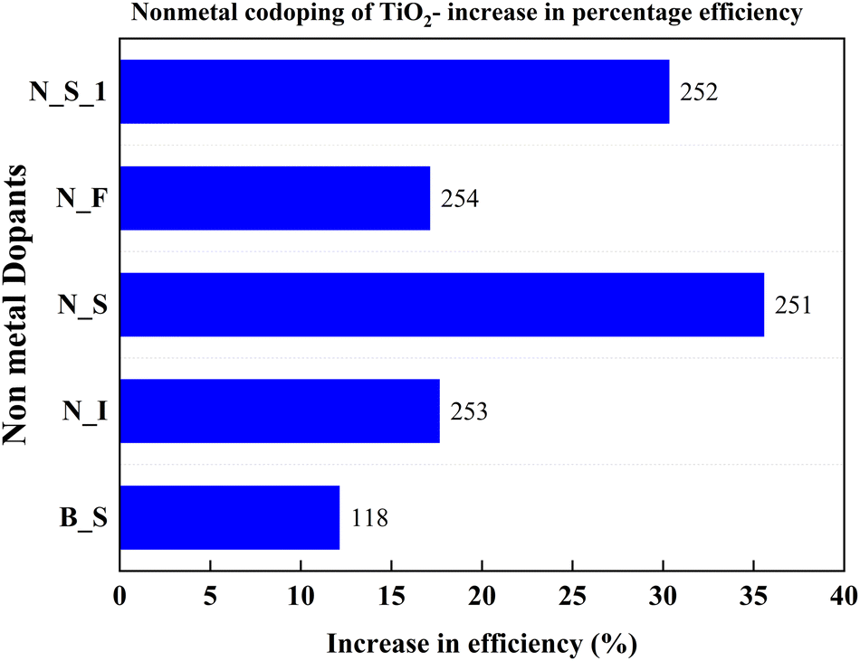 | ||
| Fig. 30 Increase in PCE of nonmetal codoped TiO2. Data points are labelled with references. | ||
Conductivity is a critical property of TiO2. Each doping attempt is towards achieving this goal. Fu Lv et al. doped anatase TiO2 with nitrogen, fluorine, and iodine to induce carriers in the lattice. This process eventually improves conductivity. N–I codoping shows the best blocking effect compared to undoped and single non-metal doped samples. The magnitude of internal charge recombination resistance (Rrec) decides the scale of the blocking effect. Usually, the charge recombination is dominated by the interfacial mesoporous TiO2, but the compact underlayer also has an influence on charge recombination. The aforementioned blocking effect empties the impurity band and improves the conductivity of TiO2 with N–I doping. So, the N–I doping inhibits electron recombination, leading to higher current density and efficiency. The N–I codoping increases electron injection between porous TiO2 and the compact layer by tuning the conduction band. The synergetic effects of the dopants result in a 17.67% increase in efficiency.253
Trap states in the conduction band of nanostructured TiO2 play a vital role in its photochemical properties. The current–time profiles of N–F doped samples are greatly influenced by the applied potential. They depend on the trap state density's current decaying behavior. At low trap density, the trap filling is fast; at high trap density, the trap filling is slower. Calculations show that the N–F doping significantly reduces the trap density due to the ability of nitrogen and fluorine to bind at the under-coordinated surface sites of TiO2.254
Doping improves the performance of DSSCs and has similar effects in other electrochemical systems. B–S doping in QDSSCs is an excellent example of codoping and consequent efficiency increase. Doping TiO2 with B–S results in bandgap narrowing and redshift in electronic absorption, leading to the increase in photocurrent response. The doping-induced efficiency is 12 percent greater compared to the bare TiO2−based QDSSC.118
4.3. Metal–nonmetal codoping
Metal–nonmetal codoping is constantly highlighted as a solution to the difficulties generated by single metal and single non-metal doping. The synergetic effect of both metal and non-metal provides higher thermal stability, lower bandgap values, and enhanced surface area. Furthermore, it reduces the carrier recombination and enhances the short circuit current.255 Doping Cu/S into the TiO2 lattice minimizes the particle size and scattering effect. In the study by Gupta et al., the concentration of sulfur remains fixed, while the copper concentration is changed from 0 to 0.5 percent.256Fig. 31 demonstrates the increase in PCE with metal–nonmetal codoped TiO2.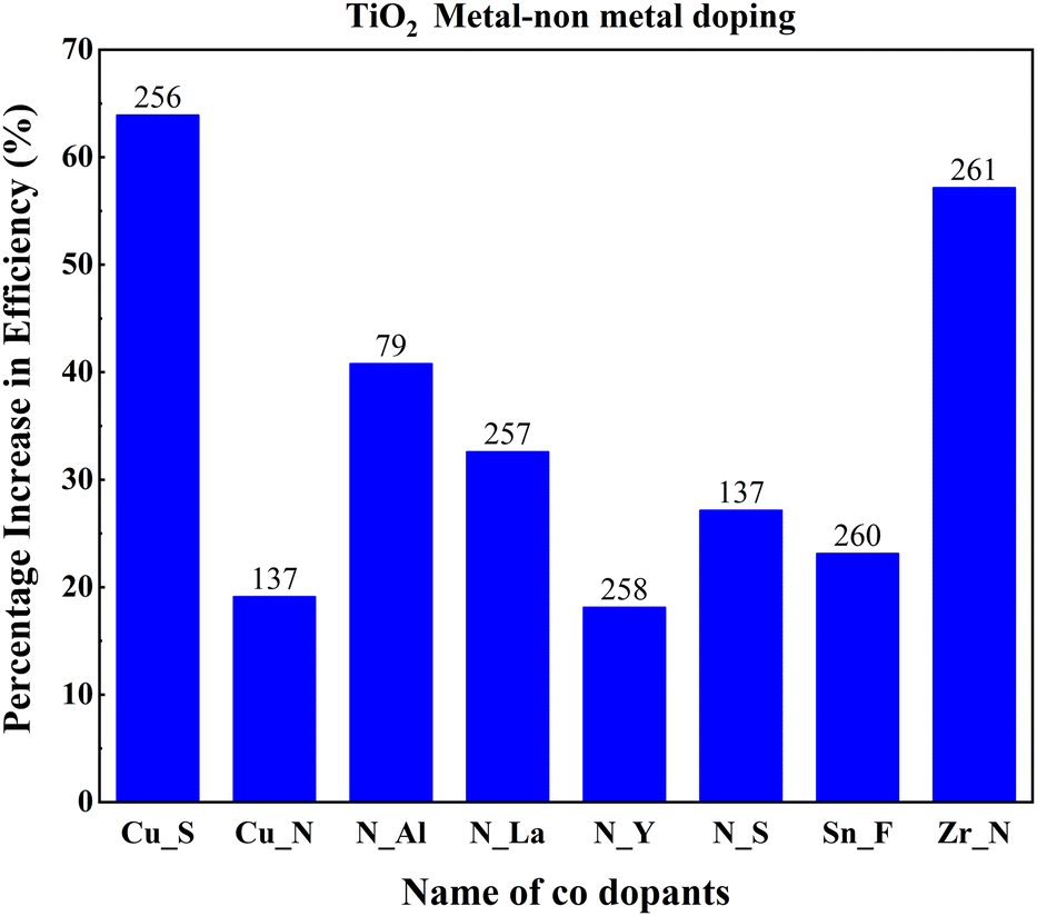 | ||
| Fig. 31 Increase in PCE with metal–nonmetal codoped TiO2. Data points are labelled with references. | ||
The synergetic effect of hybridized Cu-3d and S species with Ti-3d orbitals significantly reduced the band gap of TiO2. Consequently, this dip improved the redshift in favor of efficiency. Fig. 32 shows the varying crystallite size with 0.05 percent sulfur and copper concentration. Optimal doping plays a significant role in the Cu/S doping technique. When the doping level increased, crystals with smaller sizes started to agglomerate, clogged the microspores, and caused a severe drop in efficiency. The probability of an improved efficiency point between 0.2 and 0.3 percent doping is shown in Fig. 32. A more detailed and precise study requires finding the optimum point for maximum efficiency in Cu–S doped TiO2 anode-based cells.
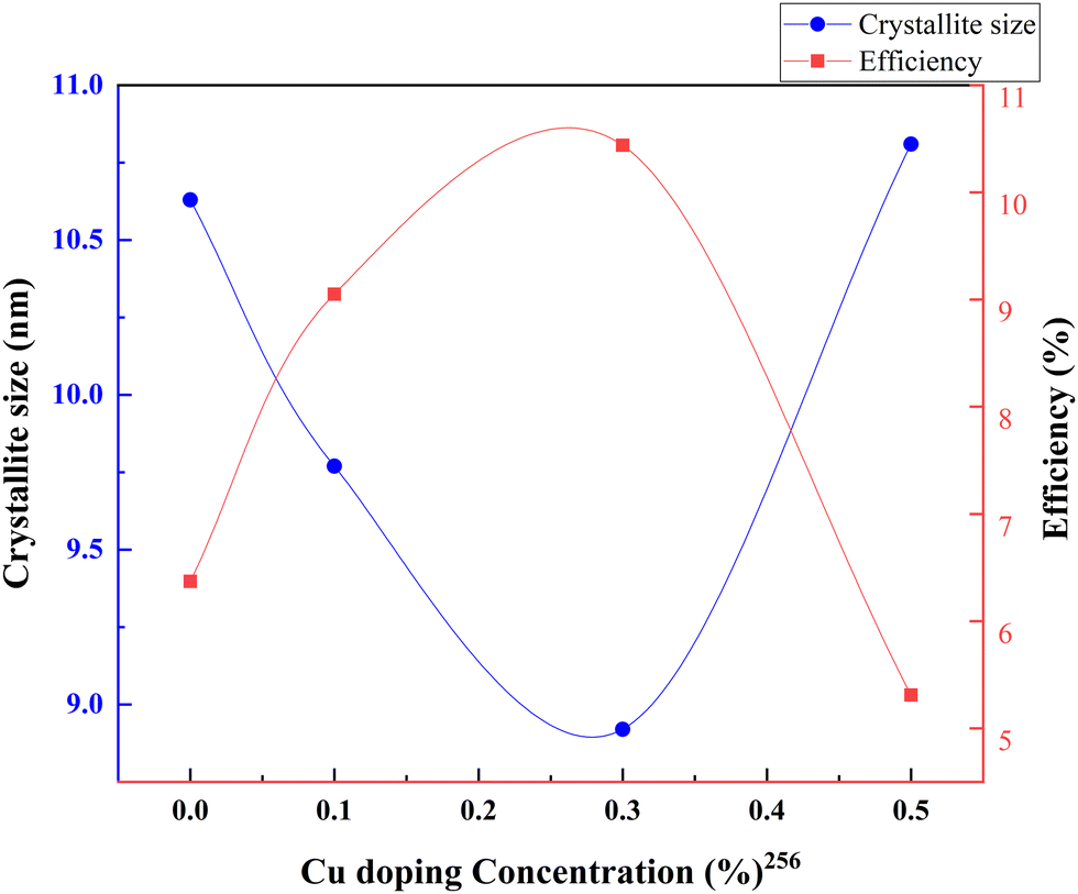 | ||
| Fig. 32 Variation of crystallite size and efficiency with copper doping concentration. Data points are labelled with references. | ||
Copper and nitrogen codoping was also investigated in the same way as copper and sulfur codoping. A DSSC made with doped TiO2 particles (crystallites) shows different efficiencies at the doping concentration of copper. Fig. 33 shows an optimum doping point in Cu–N doping, as discussed in all other examples. In this case, a maximum efficiency is attained when TiO2 is doped with copper by adding 0 to 20 mM copper nitrate into the paste, keeping the doping amount of nitrogen constant for all experiments. This tendency trails in the current generation through reduced crystallite size and increased surface area. When linking copper doping with nitrogen and sulfur, copper–nitrogen doping exhibits only a 19 percent increase in efficiency due to doping. The absence of data between 1 mM and 20 mM copper–nitrogen doping is probably the reason. According to the observations, a better optimal point for doping exists further to increase the efficiency of anodes.137
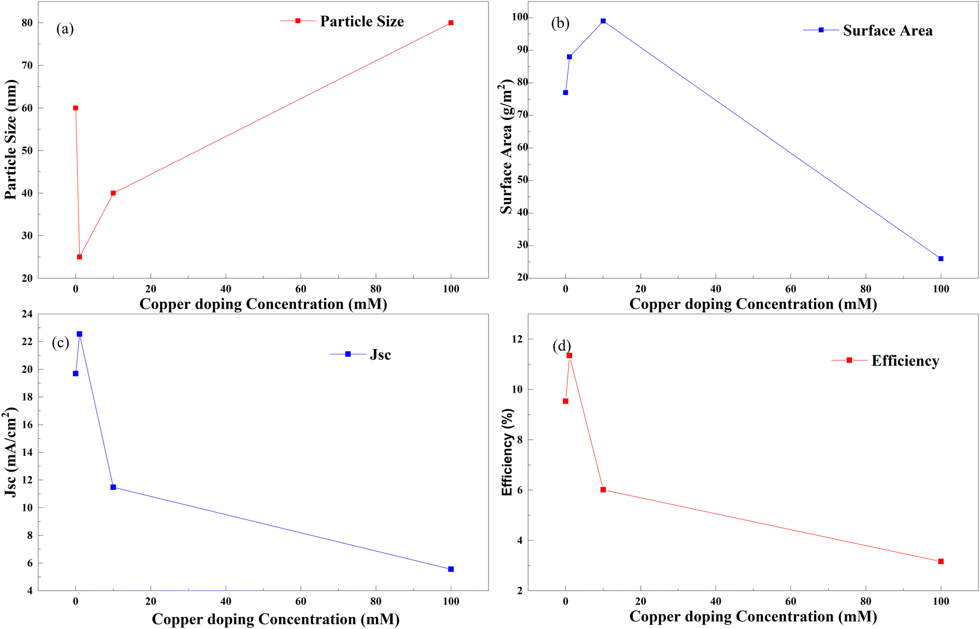 | ||
| Fig. 33 Copper doping concentration with (a) particle size, (b) surface area, (c) Jsc and (d) efficiency.137 | ||
The same trend is observed in nitrogen–aluminum doping as well. However, as the doping increases and aluminum enters the TiO2 lattice, a gradual fall in the peak intensities of the TiO2 anatase phase is observed. This fall is an indication of anatase crystal growth obstruction. An appropriate combination of aluminum and nitrogen could effectively contribute to the efficiency. Higher doping causes severe agglomeration of the nanoparticles, leading to sluggish charge transfer and enhanced charge recombination. In this case, the codoping of aluminum and nitrogen leads to a gradual decrease in bandgap energies and an electron–hole lifetime.79
Nitrogen and lanthanum codoping leads to a decrease in charge transport resistance, which effectively increases the dye absorption of the photoanode. Besides, the formation of new bonds with N, O, and lanthanum causes an increase in the disorder of the lattice structure of TiO2 and the generation of trap states. Consequently, Jsc increases, which reflects in efficiency.257
Yttrium–nitrogen doping into TiO2 shows a significant observation with an XPS scan. The TiO2 anode shows a discrepancy in the amount of dopant added through precursors and dopant in the nanoparticles synthesized. When the nominal molar ratio of added precursors TiO2–N–Y for synthesis is 100–100–0.5, the XPS observed concentrations of nitrogen and yttrium are 0.30% and 0.48%, which are different from the one we have prepared. Most studies with added precursors for doped products may have this discrepancy if the dopant ratio is not determined through the characterization technique. Nitrogen–yttrium doping also follows the same trend as other dopants in doping concentration and efficiency. The maximum efficiency is attained for a 100–300–0.5 nominal molar ratio combination sample. This is 18 percent higher compared to pure TiO2 electrodes.258
Instead of producing an efficient DSSC, silver–sulfur codoped TiO2 offered an environmentally conscious preparation approach. Even though 0.50% Ag was added for the codoping, XPS analysis showed that the anode had 0.75% silver in the atomic composition. Similar to our previous observations, when the anode had a doping concentration of 0.75% silver and 0.70% sulfur, it had the highest synergy and high-efficiency output.259
Zirconium doping with titanium increases the electron density and uplifts the Fermi level of TiO2.78 Tin is a homovalent atom to zirconium. Similar to zirconium, tin also offers lower transport resistance.81 The electron transport resistance decreases after tin doping and increases with fluorine doping. Impedance analysis shows that the dual doping increases interfacial charge recombination resistance. This resistance effectively decreases the recombination. A shorter transport time, measured with IMPS, implies a faster electron transport rate. The faster electron transport rate is favorable for charge collection and photocurrent density. The bonding may play a significant role in increasing efficiency as well. F atoms are bonded with the surface fivefold that of Ti, and the binding energy is 1 eV, showing strong chemisorption. Detailed density functional theory implementation gives more robust validation to existing arguments. Stronger bonding with Ti–F than Ti–O lowers the energy of the electrons of the valence band and leads to shifting the Fermi level towards the valence band and extending the bandgap. Both lead to the production of charge-trapping sites on the surface and subdue the charge recombination at the interface by holding trapped electrons, thus ending up in a longer electron lifetime. The longer electron lifetime is confirmed with IMVS measurements.260
Zirconium and nitrogen doping in TiO2 results in high surface area, enhanced charge transfer, and reduced charge recombination in electrochemical devices. When P25 TiO2 particles showed an efficiency of 8.32%, codoping with 0.01 zirconium and nitrogen increased the efficiency to 12.62%. While increasing the doping percentage of Zr/N in the anode, the efficiency of the cell decreased drastically. While the nitrogen doping shifts the absorption of TiO2 into the visible light region, adding zirconium amplifies the short-circuit current. The dip in the efficiency is not discussed in detail in the paper but is ambiguously correlated with the dye absorption. We conclude that an optimum efficiency point exists where various properties such as charge transfer resistance, less electron–hole recombination, and bandgap tuning increase the maximum attainable efficiency. Above this point, the doping could negatively affect the efficiency and properties of the TiO2 anode.261
4.4. Bandgap tuning and codoping
Doping is considered to be the best option to tune the bandgap of any material.77 When we introduce foreign materials into the TiO2 lattice, they can alter the properties in both ways. The Burstein–Moss effect explains the increases in the bandgap when TiO2 is doped with Cu, Ni, and Cr.262 Here, doping populates the conduction band and pushes the absorption edge to higher energies, resulting in an increased bandgap. At lower doping concentrations, doping can decrease the band gap. Doping with different elements can introduce additional energy levels within the bandgap of the TiO2. Subsequently, these levels will allow electrons with lower photon energy to reach the conduction band. Fig. 34 shows the quantitative relationship between the doped TiO2 bandgap and the corresponding increase in efficiency. The Voc, Jsc, PCE, and bandgap values of codoped TiO2 are provided in Table 7. A more detailed dataset is provided in the ESI.† While the bandgap changes between 2.5 and 4 electron volts, the PCE increases to 6 percent, an enormous difference. Whenever the TiO2 bandgap increases above 3, the efficiency tends to decrease. Finding the exact bandgap–efficiency relationship in electrochemical devices required extensive and pointed research in doping of TiO2. Doping with zirconium and nitrogen tunes the bandgap to 2.83 eV, and the increase in the PCE is 5.65%. Doping TiO2 with N–La, Al–N, Zr–N, and Cu–S tunes the bandgap around 2.7 to 2.86 eV. In this range, the efficiency is maximum for TiO2 based devices.79,256,257,261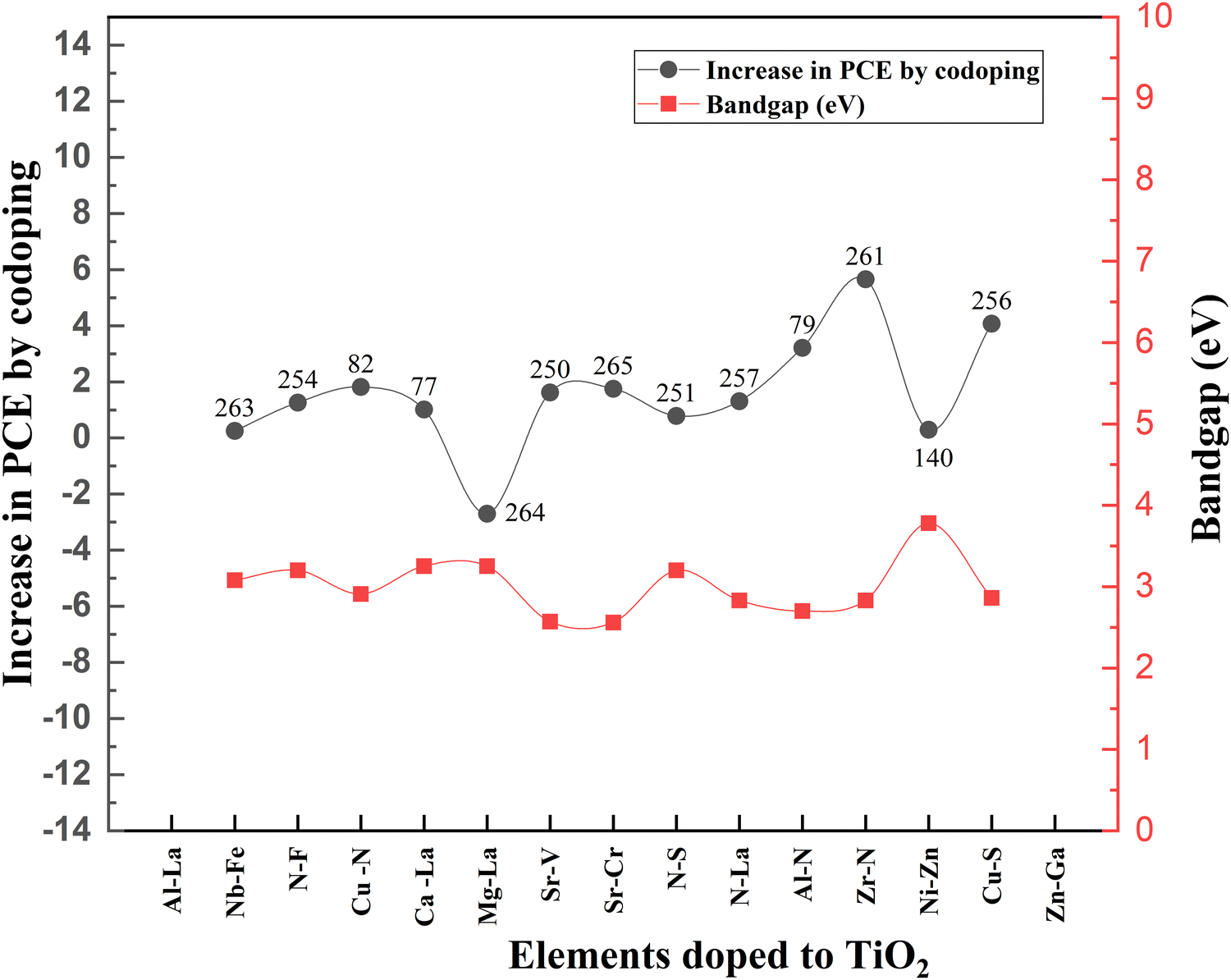 | ||
| Fig. 34 The quantitative relationship between the bandgap and increase in PCE. Data points are labelled with references. | ||
| S. no. | Elements doped into TiO2 | Bandgap (eV) | Increase in PCE through doping (%) | Ref. |
|---|---|---|---|---|
| 1 | Al–La | 3.25 | 1.33 | 77 |
| 2 | Nb–Fe | 3.08 | 0.25 | 263 |
| 3 | N–F | 3.2 | 1.26 | 254 |
| 4 | Cu–N | 2.91 | 1.82 | 82 |
| 5 | Ca–La | 3.25 | 1.01 | 77 |
| 6 | Mg–La | 3.25 | −2.7 | 264 |
| 7 | Sr–V | 2.57 | 1.62 | 250 |
| 8 | Sr–Cr | 2.56 | 1.75 | 265 |
| 9 | N–S | 3.2 | 0.78 | 251 |
| 10 | N–La | 2.83 | 1.31 | 257 |
| 11 | Al–N | 2.7 | 3.21 | 79 |
| 12 | Zr–N | 2.83 | 5.65 | 261 |
| 13 | Ni–Zn | 3.78 | 0.29 | 140 |
| 14 | Cu–S | 2.86 | 4.07 | 256 |
| 15 | Zn–Ga | 3.2 | 3.1 | 200 |
TiO2 conduction band edges with doping Mg2+ ions are well studied, but La doping is not profound. The Mg–La doping increases the bandgap by 0.05 eV with doping. Contradictory to this, Ca–La and Al–La codoping results in the decrease of the bandgap. Lower Voc values associated with Ca–La codoping in TiO2 are found to reduce the bandgap. Nevertheless, all these band gap observations are made using Tauc plots, which could affect the accuracy of these measurements. A dopant with a smaller ionic radius than Ti4+ can enter the titanium lattice. When this dopant goes in, it can create more impurity levels and increase the recombination rate. Consequently, these impurity levels are due to the bandgap changes in the case of Al3+ and Mg2+. Moreover, Ca2+ ions have larger ionic radii than Ti4+ ions and cannot enter the lattice and get blocked outside. Doping with Ca–La causes a decrease in bandgap and has a positive impact on charge transfer.77,114
In copper and sulfur codoping into TiO2, the copper doping concentration changes while keeping the sulfur doping concentration at 0.05%. Their doping ratios are validated with EDAX. When the copper doping increases, the band gap of the doped sample is reduced due to the synergic effect of both dopants. The 3d and s species of copper hybridize with Ti-3d orbitals and produce localized defect levels above the maximum of the valence band. These defect levels effectively shift the valence band towards a longer wavelength. Impurity levels and oxygen doping can widen or narrow the bandgap.256Fig. 35 exemplifies the decrease in bandgap with Cu/S codoping.
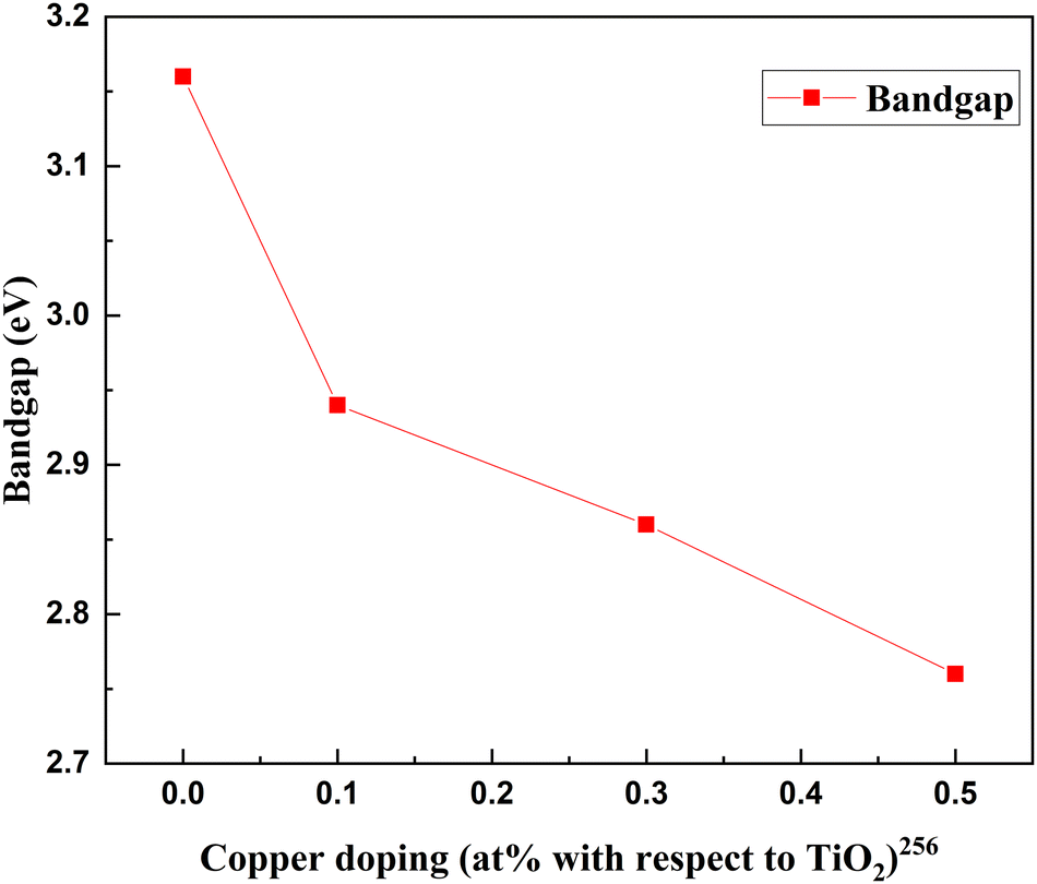 | ||
| Fig. 35 Decrease in bandgap with Cu/S codoping. | ||
Impedance measurements by intensity-modulated photocurrent spectroscopy (IMPS) and intensity-modulated voltage spectroscopy (IMVS) are standard techniques for understanding charge carrier kinetics in oxides. The time constant can be calculated from the impedance semicircle of the Nyquist plot. IMPS and IMVS analysis can provide electron lifetime and transport time details. IMPS spectra consist of two semicircles, one representing the trap limited transport time and the trap free transport time. The effect of doping can be determined from the trap mediated transport time and electron lifetime.
Doping TiO2 with Fe has a shorter trap limited transport time and a longer electron lifetime than bare TiO2. Nb–Fe codoped TiO2 samples take longer trap limited transport times and longer electron lifetimes than the other samples. This observation leads to the guesstimation that during Fe doping of TiO2, there is the formation of Ti3+ donors and Fe traps. Shallow Ti3+ donors cause shorter transport times, while Fe has multiple trapping and de-trapping events, causing a longer lifetime. Fe and Nb codoping introduces Nb5+ into the TiO2 lattice, creating further shallow Ti3+ donors and Nb5+ traps. These shallow donors extend the electron lifetime through electron excitation and trapping transport, allowing more diffusion under illumination. Oxygen vacancies generated during doping can act in favor of or against the charge collection during transport. However, open circuit photo-potential transient analysis shows that the Nb addition to Fe-doped TiO2 facilitates charge relaxation through the passivation of deep oxygen vacancies generated by Fe doping. So, considering the OCP analysis, deep oxygen vacancies in the shallow levels may favor electron capture and de-trapping during photoexcitation.134
Doping TiO2 with Fe does not contribute much to bandgap engineering. Nevertheless, doping with Fe and Nb together significantly tunes the valence band position. The Nb doping reduces the bandgap by 0.01 eV, and the valence band position shifts to 0.11 eV. There are also similar effects on the conduction band edge. Even though the final bandgap of TiO2 does not seem affected, there is an influential band re-tuning with the codoping. Only doping, donor generation, and trap state generation can account for this bandgap tuning.
Nitrogen and sulfur codoping also shows a reduction in the bandgap. Nitrogen is responsible for bandgap reduction, and sulfur facilitates the electron transfer process. Considering strontium and vanadium codoping, V doping into TiO2 ends up in the stoichiometric reduction of Ti4+. Vanadium is also responsible for the formation of isolated energy levels near the conduction and valence bands, contributing to the PCE. The reduction facilitated by V leads to increased carrier density and improvement in photoresponse. At the same time, introducing strontium, a relatively high ionic radius ion (Sr2+), causes distortions in the TiO2 lattice. These distortions accumulate oxygen vacancies across the lattice and extend the life of photoexcited electrons and holes. Chromium doping introduces isolated energy levels near conduction and valence bands like V. The reason for these isolated energy levels is excess holes. These holes are responsible for the acceptor band near the TiO2 valence band.250–252,265
Similar to copper–sulfur doping, zirconium–nitrogen codoping causes an increase and decrease in the bandgap.261Fig. 36 shows the Zr/N doping concentration in TiO2 and the corresponding change in the bandgap.
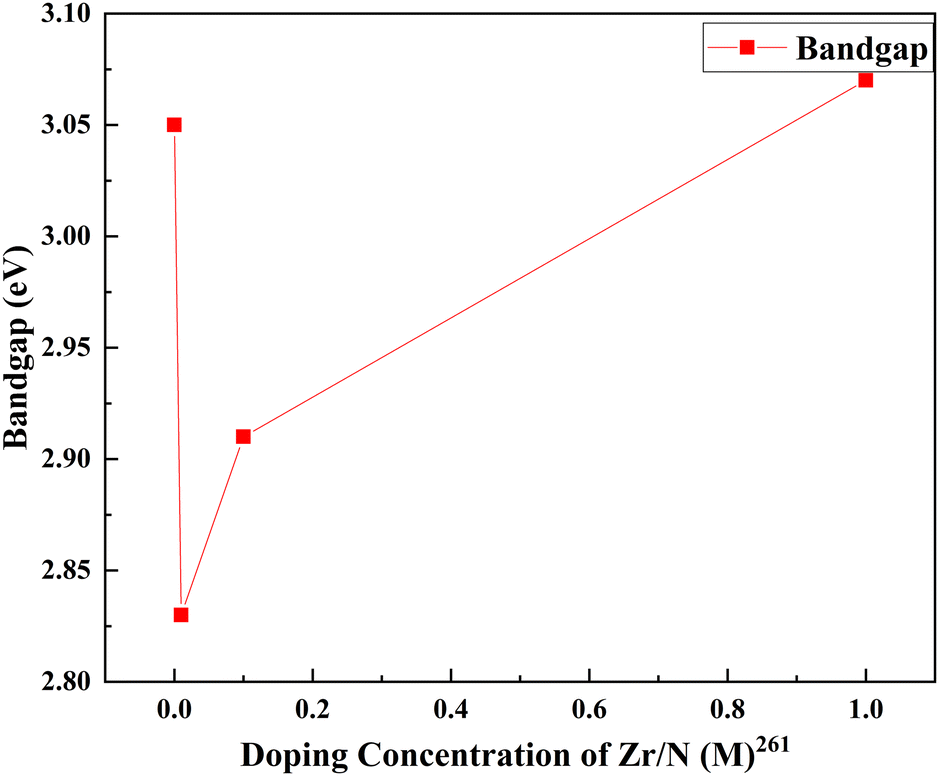 | ||
| Fig. 36 Zr/N doping concentration in TiO2 and the corresponding change in bandgap. | ||
This study argues that the change in bandgap is connected with particle size variation (Fig. 37). When the particle size increases, the bandgap decreases. Simultaneously the reduction in bandgap results in increased cell efficiency. On the other hand, aluminum–nitrogen doping shows a similar bandgap trend to Zr/N.79 There is a limitation to concluding the doping concentration and bandgap relationship due to the non-uniformity of reported doping concentration units. Fig. 36 roughly describes the connection between the bandgap and doping concentration. More or less, each dopant pair shows a decrease in the bandgap when materials are added in small amounts. However, adding materials beyond an optimum point decreases the doping effect and increases the bandgap.
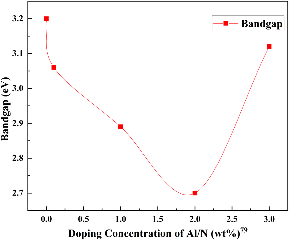 | ||
| Fig. 37 Doping concentration vs. bandgap. | ||
5. Composite doping
Composite materials are macroscopic combinations of two or more distinct materials having a finite interface. They have been introduced into several industries in diverse forms. Doping and adding composites into TiO2 have attracted considerable attention since they have significantly increased the PCE of DSSCs. Adding various composite nanostructures into TiO2, including nanoparticles, nanobelts, and nanofibers, through different synthesis methods has advantages in tailoring its properties. Creating TiO2-elemental composites plays a significant role in the flexibility and performance of the resulting material. In some studies a significantly low amount of material is added into TiO2 for better performance. This is called composite doping. This composite impurity added to the TiO2 can alter the photoanode performances and increase the efficiency. Composite dopants include metal composites, MW CNT composites, semiconductor composites, polymer carbon nitride composites, carbonate composites, and amine composites.266–269Functional nanocomposites involving metals improve the photocatalytic electron transfer process. Semiconductor–metal composites can sustain charge separation to a great extent. When Pt creates an ohmic type contact with ZnO, Au–ZnO creates a Schottky type contact.270,271 Introducing Au into bulk TiO2 and producing a metal nanoparticle composite reduces charge recombination, increases thermal and chemical stability, and inhibits non-radiative quenching.272 In this case, the Au–TiO2 composite has higher absorption due to the surface plasmon effect provided by Au. In another study, 0 to 0.6 wt% of Ag nanowires coated with SiO2 were applied to TiO2. The strength of the material, photon capture ability, and Jsc were significantly increased.273 F. Zheng and Z. Zhu showed that Au nanoparticles in TiO2 nanofibers exhibited broad surface plasmonic absorption. The Au concentration in the anode conversely affected the DSSC performance beyond the optimum loading.274 Considering the available metal composite data, a N,S codoped silver nanoparticles decorated photoanode showed an exceptional increase in PCE. When the control sample (bare TiO2 based) had 2.57 percentage efficiency, a codoped composite sample-based DSSC exhibited 8.22 percentage efficiency. The concentration of Ag NPs plays a dynamic role in the efficiency of the DSSC. When N,S doping reduced the bandgap, shifted the optical absorption towards the visible region, and suppressed the charge recombination, Ag nanoparticles harvested more light owing to the surface plasmon effect. The synergetic effect of codoping and Ag silver nanoparticles amplified the photocurrent generation, and consequently the efficiency of the DSSC.252Fig. 38 compares the effect of metal composite doping on the percentage increase in PCE.
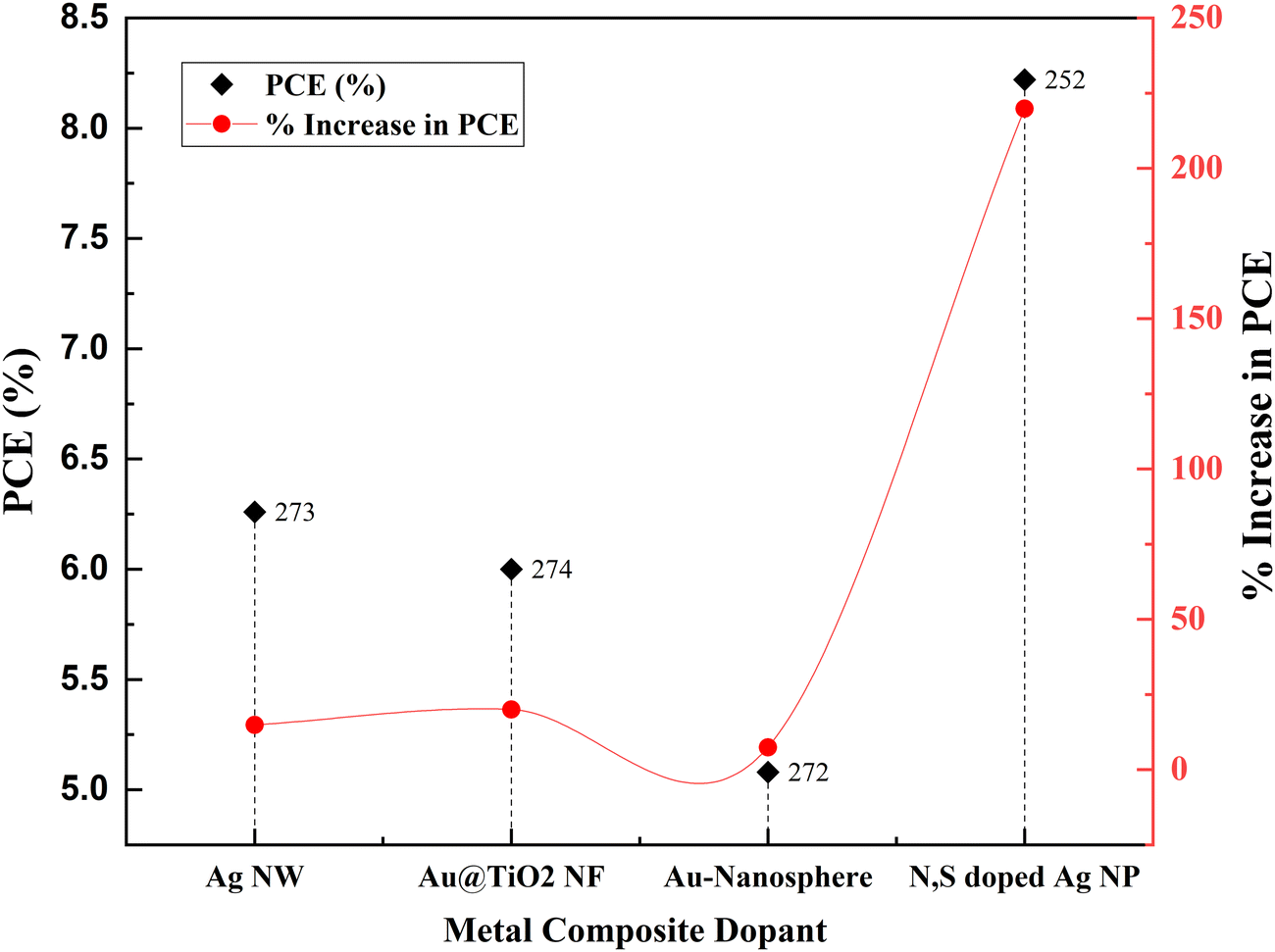 | ||
| Fig. 38 Metal composites and percentage increases in PCE. Data points are labelled with references. | ||
TiO2, dyes, and electrolyte interfaces have been studied since the beginning of the DSSC invention. Significant research is on the electron injection from dyes into the conduction band of TiO2 since it is a crucial mechanism in determining efficiency. Various semiconductors were developed and deposited over TiO2 to modulate the interfacial properties. Some include metal oxide semiconductors with wide bandgaps such as NiO, Bi2S3:Eu3+, Cu2O, NiO, NiO:Eu+Tb, and ZnO nanobelts. ZnO and TiO2 exhibit identical physical properties and bandgap values. The electron mobility and crystallization ability of ZnO are better than those of TiO2. But ZnO-based photoanodes have comparatively lower PCEs than TiO2 based DSSCs. This is primarily due to the poor dye-ZnO electron injection kinetics. The synergy of ZnO nanobelts and TiO2 contributes to PCE by improving charge transfer efficiency and large surface area. ZnO nanobelt@TiO2 also shows an increased carrier lifetime and fast electron transfer.269
Similarly, Bi2S3:Eu3+ can act as the down-conversion luminescent composite anode material. Bi2S3 transfers electrons to TiO2, and the Eu3+ metal ion improves photocatalytic performance. P-type NiO is a wide bandgap semiconductor that is thermally and chemically stable. A photoanode, a combination of NiO and TiO2, enhances the charge separation and increases the PCE.275 These samples—Bi2S3:Eu, NiO, NiO: Eu, and Tb—display excellent efficiency and only a slight increase in PCE due to composite doping. On the other hand, Cu2O shows a tremendous increase in PCE. Cu2O studies have been conducted by fabricating QDSSC, CdS, and ZnS layers. Cu2O is one of the most potential p-type semiconductors for photovoltaic applications. It has high charge mobility and high minority carrier diffusion length. When the control QDDSC shows mere 1.17% efficiency, a Cu2O incorporated QDDSC offers 3.01% efficiency. Contrary to the PCE, the effect of adding Cu2O is much higher.276Fig. 39 shows the increase in PCE with each semiconductor composite dopant we have discussed.
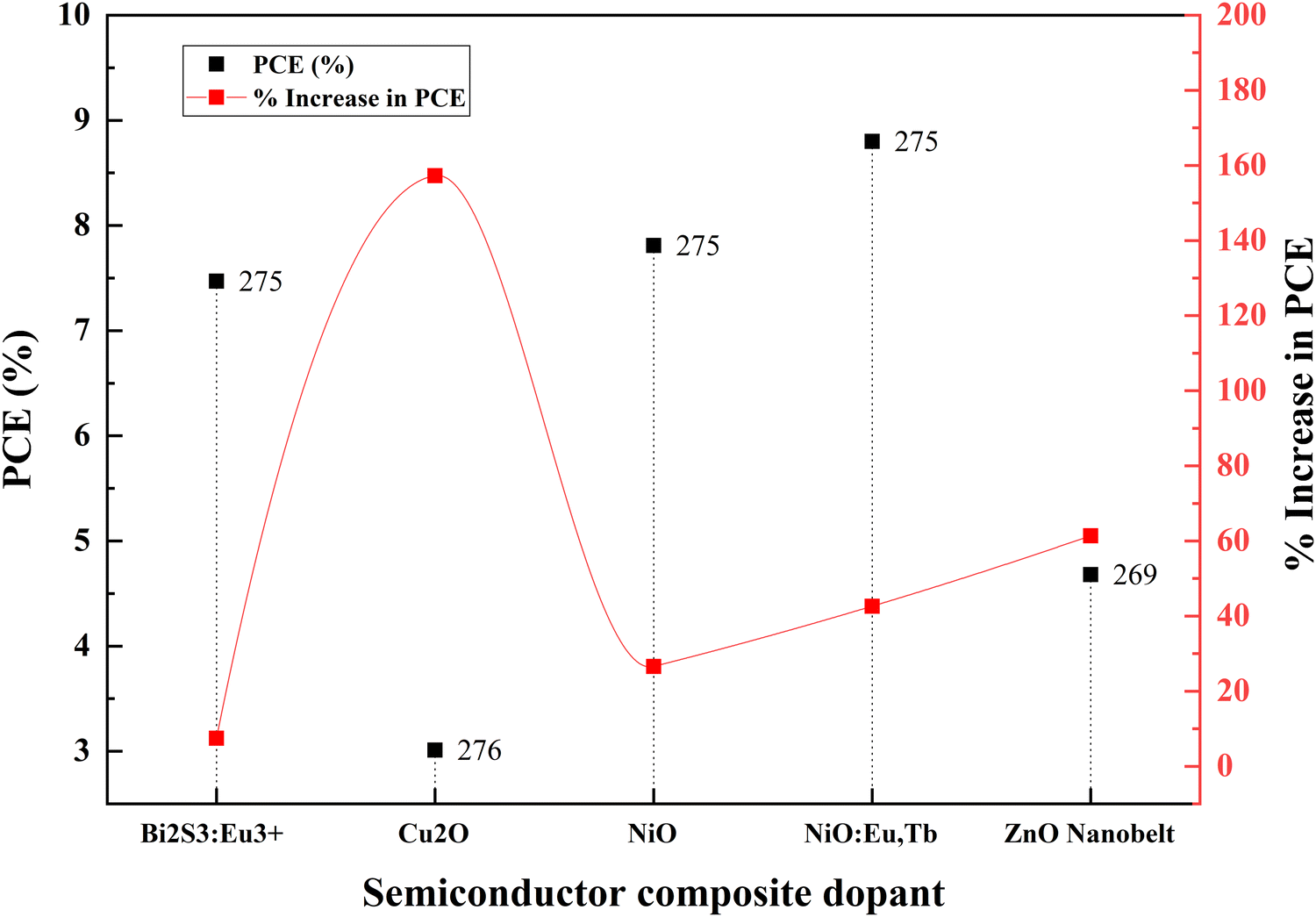 | ||
| Fig. 39 Increase in PCE with different semiconductor composite dopants. Data points are labelled with references. | ||
Carbon nitrides, carbonate groups, amines, and carbon nanotubes have also been used for creating composites. A graphene–C3N4–TiO2 composite exhibits a 29.3% improvement in PCE when used as a photoanode in a QDSSC. It has a suitable band structure and chemical-thermal stability for use as a photoanode. This material increases the roughness and makes the loading of CdS QDs easier.268
When comparing the efficiencies of other composite dopants, the efficiency of g-C3N4@TiO2 seems to be less. There are two studies on carbonate doped TiO2: one in 2016 and the other in 2018.227,277 Carbonate doping results in a structure called a carbonate doped mesoporous microstructure (doped MS). A carbonate-doped mesosphere structure-based DSSC has higher PCE than carbonate doped MS nanospheres. Nevertheless, the increase in PCE is more in DSSCs based on carbonate based MS nanospheres.227 Carbonate doping produces a band tail state which effectively reduces the bandgap. Carbonates increase porosity and decrease electron recombination, and enhance the redox coupling. In the case of a carbonate-MS-NS@TiO2-based photoanode, the carbonate reduced the internal cell resistance and improved the electron lifetime. The reduced internal cell resistance led to high light absorption and fast electron transport in carbonate based DSSCs.277Fig. 40 shows the increase in PCE with different composite dopants such as carbonates, amines, and carbon nanotubes.
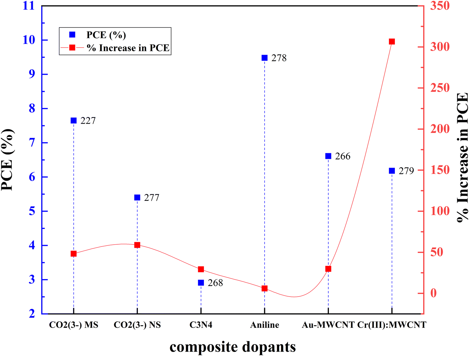 | ||
| Fig. 40 Increase in PCE with different composite dopants. Data points are labelled with references. | ||
Aniline, an amine, has recently been doped into TiO2 to achieve better photocurrent generation. Reduction of TiO2 nanocrystal size using long-chain monoamines decreases the transmission. Amine capping improves efficiency and increases light scattering to a great extent. Amine groups such as aniline and o-phenylenediamine have active sites that can enhance PCE. The ability of nonmetal dopant's N2p and O2p orbitals to modify TiO2 and reduce the deposition in interstitial sites has drawn attention towards non-metal doping. The operational strategy behind amine group doping is to improve photocurrent generation, increase electron transfer dynamics and reduce recombination in the scattering layer. It has long been known that amines affect morphology (by controlling TiO2 size and providing an increased surface area) as well as reflectivity and PCE.278 In this study, aromatic amine passivated TiO2 is prepared through a hydrothermal method. After amine capping, there is a reduction in crystallinity, and broadening in the XRD peak. Due to the formation of coordination bonds, there is a shift observed in the XRD peak. From reflectance studies, it is evident that amines increase the absorbance. By using FTIR, it is clear that the broadened N–H stretching reveals the fermi resonance of N–H and O–H peaks. The overlapping of N–H and Ti–OH bonds confirms the presence of aromatic amines in the TiO2 lattice. The increase in reflectivity is due to the amines attached to the crystal surface. These amines reduce light penetration into the TiO2 surface and the pi electrons in aromatic rings absorb light. This effectively reduces the scattering and increases the absorption.267 However, the control cell efficiency and amine-doped photoanode-based cell efficiency are high. The effect of amine capping is insignificant compared to other composite dopants.267
Cr(III) doping into TiO2/MWCNTs results in an incredible increase in PCE. Impurities in the TiO2 lattice act as charge trapping sites and improve the rate of charge transport in DSSCs. MWCNT@TiO2 alone increases the efficiency by 4.6 percent. The percentage increase in PCE is around 300%. When Cr(III) is added to the matrix, the percentage increases from 6.18% to 7.69%. The overall increase in efficiency becomes 6.17 percent, which is around a 400 percent increase.279 Au nanoparticles and MWCNT composites also enhance the PCE by 30 percent. Compared with Cr(III), this is less. However, the control DSSC cell efficiency is higher here (5.09%) than the Cr(III)@MWCNT composite (1.52%). An Au@MWCNT composite-based DSSC has comparable efficiency (6.61%). This improvement in efficiency is attributed to the synergetic effect of Au and MWCNTs through improved charge generation and enhanced light absorption.266
6. Dopant distribution in the TiO2 lattice – summary
Numerous studies have examined how dopants are distributed and where they are located within the TiO2 lattice. This positioning information is collected from XPS, FTIR and XRD observations. The TiO2 lattice can integrate a dopant to:(a) Substitute Ti4+,
(b) Substitute Ti4+ and produce Ti3+,
(c) Substitute O2−,
(d) Substitute O2− and induce Ti3+ formation,
(e) Go into interstitial sites and
(f) Go into surface interstitials.
The ionic radius of the dopant is a critical factor influencing the nature of doping. Dopants with a comparable atomic size of Ti4+ substitute it and causes slight rearrangements and distortions in the lattice. In rare cases, these substitutions lead to the surge of Ti3+ in the lattice. The ionic radius depends on factors such as coordination number, spin state, crystal radius, and electron configuration. Even in detailed ionic radius studies, if there is an uncertainty in coordination number or a deviation from the radius vs. valence plots then the obtained ionic radius values may not be that reliable.280 Keeping that aside, a significant number of dopants replace Ti4+ such as Mg2+, Ca2+, Sr2+, Sc3+, Y3+, Zr4+, V5+, Nb5+, Ta5+, W4+, Cr3+, Mn2+, Fe3+, Co2+, Ni2+, Cu2+, Zn2+, Cd2+, In3+, Sn4+, Bi3+, and Al3+. Among these, bigger ionic radius atoms such as Sr2+, Bi3+, and Ca2+ cause lattice distortions and changes in crystalline information.
It has been suggested that replacing Ti4+ ions may result in Ti–O–Cr structures and oxygen vacancies. This Ti4+ withdraws electrons from superficial hydroxyl groups and reduces to Ti3+:
| Ti4+ + Cr3+ + e(O2−) →T3+ + Cr3+ + Ovacancy |
Iron (Fe2+) and copper (Cu2+) also result in the creation of Ti3+ trap states, just like chromium (Cr3+) does. In a way analogous to this, fluorine (F−) substitutes oxygen and produces Ti3+ ions, improving the effectiveness of charge collection. Due to its great electronegativity, it interferes with the CB of TiO2 and prevents electron recombination. Since oxygen (O2−) and nitrogen (N3−) have similar ionic sizes, nitrogen can easily replace oxygen. There are some conflicts regarding the oxidation state and position of nitrogen dopant in the TiO2 lattice. The presence of Ti–O–N bonding indicates the presence of N− ions.55,224,229–231,281 FTIR, XPS, and XRD studies show that lithium (Li+) and boron (B3+) are introduced into the interstitial sites.
Some researchers claim that no rare earth elements can pass through the TiO2 lattice due to the larger ionic size. They either form Ti–O–La bonding on the surface or are in the surface interstitials of TiO2. This bonding increases the surface area and oxygen vacancies of TiO2. When doped with rare earth elements, photovoltaic devices that use TiO2 perform better. When doped, La3+, Nd3+, Sm3+, Eu3+, Gd3+, Tb3+, Er3+, and Yb3+ remain in the surface interstitials.
Sulfur shows a peculiar behavior when doped into TiO2. It is challenging to establish the oxidation state of sulfur when doped.223 Although sulphur has oxidation states ranging from S6+ to S2−, there is no evidence that S2− (1.7 Å) would replace O2− (1.22 Å) atoms; instead, S6+ (0.29 Å) would replace Ti4+ (0.64 Å). In addition, O2− and Ti4+ ions with various oxidation states might get randomly substituted, significantly disturbing the lattice.245,246 The entire discussion is summarized in Fig. 41, which illustrates the distribution of dopants in the TiO2 lattice.
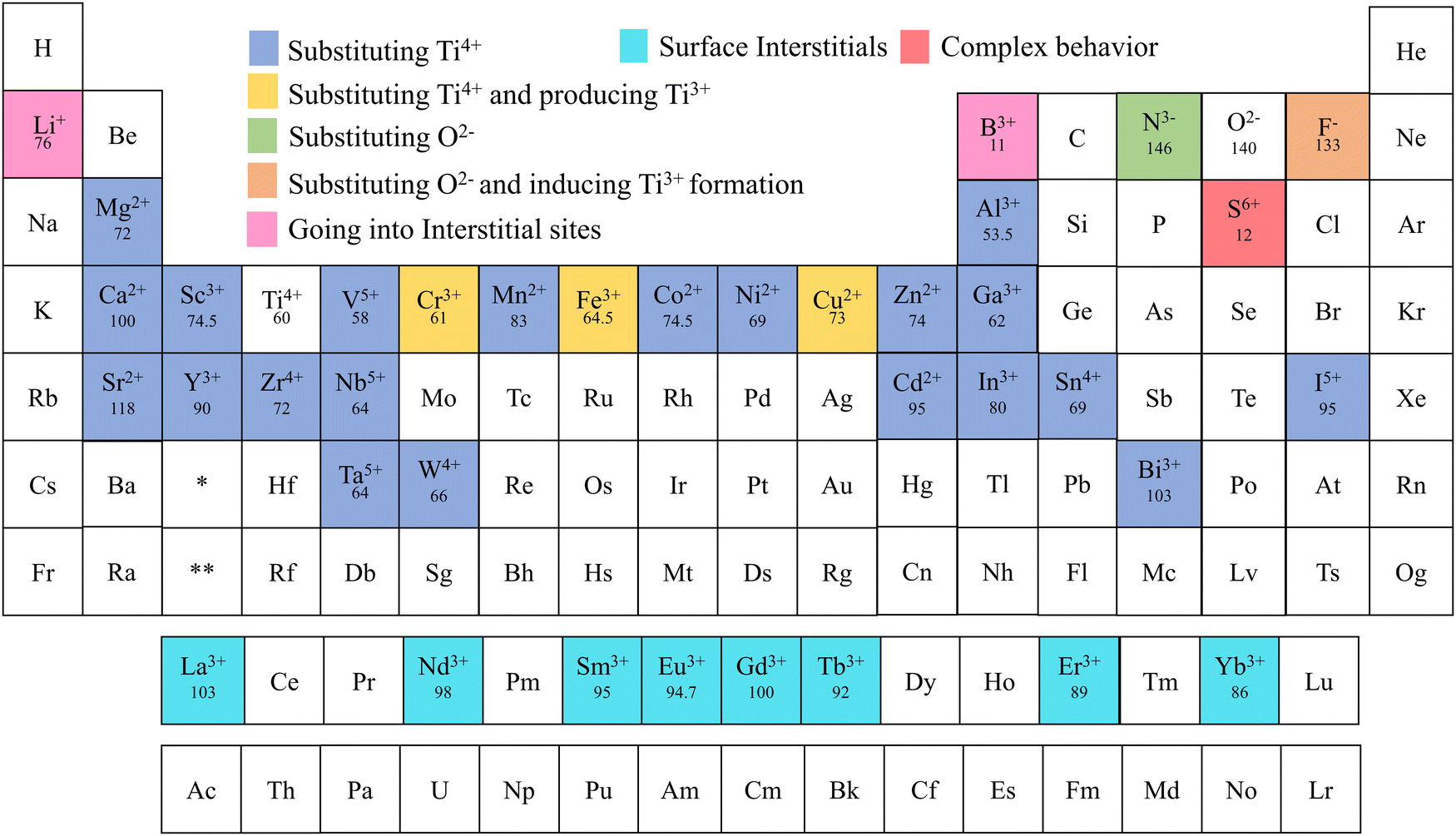 | ||
| Fig. 41 Distribution of dopants in TiO2 (references provided in Table 8). | ||
| Name of the element | Ionic state | Ionic radius (pm) | Lattice interaction | Ref. |
|---|---|---|---|---|
| Lithium | Li+ | 76 | Going into interstitial sites | 86 |
| Boron | B3+ | 11 | Going into interstitial sites | 126 |
| Nitrogen | N3− | 146 | Substituting O2− | 239 |
| Fluorine | F− | 133 | Substituting O2− and inducing Ti3+ formation | 217 |
| Magnesium | Mg2+ | 83 | Substituting Ti4+ | 88 |
| Aluminium | Al3+ | 53.5 | Substituting Ti4+ | 77 |
| Sulfur | S6+ | 12 | Complex behavior | 245–247 |
| Calcium | Ca2+ | 100 | Substituting Ti4+ and distorting the lattice | 77 |
| Scandium | Sc3+ | 74.5 | Substituting Ti4+ | 127 |
| Vanadium | V5+ | 58 | Substituting Ti4+ | 147 |
| Manganese | Mn2+ | 83 | Substituting Ti4+ | 151 |
| Chromium | Cr3+ | 61 | Substituting Ti4+ and producing Ti3+ | 250 |
| Iron | Fe3+ | 64.5 | Substituting Ti4+ and producing Ti3+ | 153–155 |
| Cobalt | Co2+ | 74.5 | Substituting Ti4+ | 156 |
| Nickel | Ni2+ | 69 | Substituting Ti4+ | 136,158 |
| Copper | Cu2+ | 73 | Substituting Ti4+ and producing Ti3+ | 151,154,159 |
| Zinc | Zn2+ | 74 | Substituting Ti4+ | 200 |
| Gallium | Ga3+ | 62 | Substituting Ti4+ | 209 |
| Strontium | Sr2+ | 118 | Substituting Ti4+ | 99 |
| Yttrium | Y3+ | 90 | Substituting Ti4+ | 141,165,166 |
| Zirconium | Zr4+ | 72 | Substituting Ti4+ | 72,167 |
| Niobium | Nb5+ | 64 | Substituting Ti4+ | 171,172 |
| Cadmium | Cd2+ | 95 | Substituting Ti4+ | 144 |
| Indium | In3+ | 80 | Substituting Ti4+ | 199 |
| Tin | Sn4+ | 69 | Substituting Ti4+ | 203 |
| Iodine | I5+ | 95 | Substituting Ti4+ | 213,214 |
| Tantalum | Ta5+ | 64 | Substituting Ti4+ | 178 |
| Tungsten | W4+ | 66 | Substituting Ti4+ | 146 |
| Bismuth | Bi3+ | 103 | Substituting Ti4+ | 66,201 |
| Lanthanum | La3+ | 103 | Surface interstitials | 114–116 |
| Neodymium | Nd3+ | 98 | Surface interstitials | 117 |
| Samarium | Sm3+ | 95 | Surface interstitials | 104 |
| Europium | Eu3+ | 94.7 | Surface interstitials | 70,107 |
| Gadolinium | Gd3+ | 100 | Surface interstitials | 106 |
| Terbium | Tb3+ | 92 | Surface interstitials | 106 |
| Erbium | Er3+ | 89 | Surface interstitials | 108,109 |
| Ytterbium | Yb3+ | 86 | Surface interstitials | 107 |
7. Conclusion
This review developed a framework to analyze the doping of TiO2 based on the PCE of sensitized solar cells. This review helps researchers to identify, analyze and plan doping in TiO2 electrode-based power sources. Beyond this review, this framework can be used for all electrochemical systems, including hydrogen generation, supercapacitors, and batteries. We identified and summarized significant elements in the periodic table doped into TiO2 and their effect on the material's PCE, Jsc, Voc, FF, and morphology.We compiled information on TiO2 dopants, such as the treatment/coating used, sub-type of doping, structure, synthesis and fabrication method, Voc (V), photocurrent density (mA cm−2), FF, PCE (%), percentage increase in efficiency due to doping, bandgap (eV), application, sensitizer/dye, and periodic classification of element types (which are included in each section). We have 106 observations where single-element doped TiO2 is used for developing DSSCs, 34 data points where codoped TiO2 is used when making DSSCs, and 15 data points where composite doped TiO2 is employed to fabricate DSSCs. According to our knowledge, this is the largest, complete information data set available until now.
Doping is not merely creating a change in electronic band structure; rather, it is altering the morphology and distribution of atoms throughout the lattice, and how these factors affect PCE. Throughout the review, we discussed how doping impacts the TiO2 crystal structure, alters the bandgap, and affects PCE. According to electron transfer dynamics studies, the morphology of the crystal surface influences the inhomogeneous distribution of the conduction band.27,29Fig. 42 features how doping increases and decreases PCE. In general, all the post-transition element dopants, nitrogen, Al–La, Zr–N, and Ca–La (codopants) show high charge transfer resistance compared to other dopants. It is also found that bigger atoms that are not able to penetrate the lattice facilitate the charge transfer process.
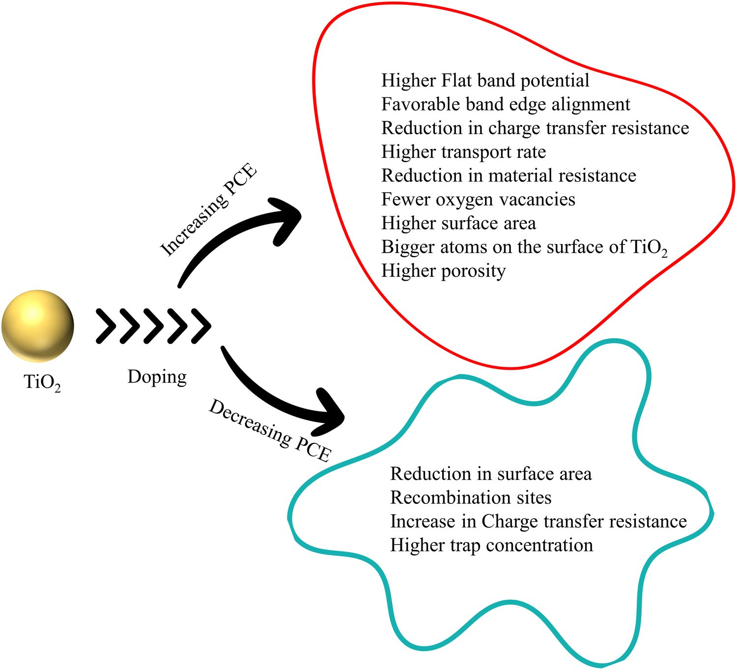 | ||
| Fig. 42 Summary of TiO2 doping. | ||
Three main factors which affect the PCE have been identified as the concentration of dopant, the size of doped TiO2 particles, and the band gap of the doped TiO2 electrode. The concentration of dopant is critical in the doping procedure. The concentration of dopant affects the size of dopant, recombination rate, transport rate, film resistance, diffusion coefficient, and oxygen vacancies. These effects are discussed with examples of Sr, Gd, Sc, V, Zr, and Nb doping.99,106,127,145,170,184,228 The efficiency decreases when the dopant concentration is below or above an optimum amount. The challenge involved in doping is finding the optimum point of peak performance. Having a control sample is necessary to understand the research progress in global standards. Many research papers lack data on the bare TiO2-based control cell to compare the doping effect and understand the role of doping in PCE. Voc, Jsc, or FF alone is not enough to comprehend the effect of doping. We need to determine the increase in PCE from that of the control-based DSSC sample. However, to summarize, Voc is increased using Mg, Cu, Nb, W, Ga, In, N, and S-doped TiO2, whereas Zr, Ag, and Ca–La doped TiO2 reduce Voc. The short circuit current increases in Sr, B, Sb, Nb, I, N, S, N–L, Ag, and Au-doped TiO2, but the Jsc decreases in Mg-doped TiO2.
The size and morphology of the doped samples are altered by doping. As a result of doping, nanoparticles, nanowalls, nanotubes, nanowires, and nanoflower structures have been created. The doped material has optimum dimensions that provide the highest PCE, similar to the concentration's influence on PCE. When the dimensions increase above this optimum point, the PCE is drastically reduced. The particle/crystallite size and doping concentration impact PCE. A material's bandgap has an impact on its electrical and optical characteristics. The PCE increases as the bandgap narrows. Some scientists contend that the bandgap influences PCE as a result of the bandgap influencing crystallite size.
Among all of the doping methods, codoping might be referred to as sensible doping. Codoping correlates the synergistic effect of two or more dopants, contributes to both Voc and Jsc simultaneously, and improves PCE. Single dopants contribute to either Voc or Jsc. Their synergetic effect also contributes to thermal stability, reduction in the bandgap, and enhanced surface area. One element enhances the short-circuit current, boosts electron transfer, and minimizes carrier recombination. The other element contributes to Voc, provides isolated energy levels close to the conduction band, lowers the bandgap, and participates in codoping. Codoping significantly boosts carrier density and enhances photoresponse.
Regarding green energy technology, doping has a bright future in research and applications. A negligible amount of resources can alter the properties of non-toxic, abundant semiconductors so they serve as excellent light-harvesting energy materials. This review has the highest PCE data to the authors’ best knowledge. It gives a holistic view of doping of TiO2 based on PCE in sensitized solar cells. This review will help future researchers understand the role of TiO2 dopants in PCE.
Author contributions
Prasanth Ravindran – supervision and writing (review & editing). Aparna Markose and Debanita Das – conceptualization, data curation, investigation, methodology, writing, and data analysis – (original draft). Aparna Markose – visualization and graphics.Conflicts of interest
The authors declare no conflict of interest.Acknowledgements
We acknowledge the funding from the South Asia Foundation (SAF), the Ministry of New and Renewable Energy (MNRE), the University Grants Commission (UGC), the Council of Science and Industrial Research (CSIR), and the Board of Research in Nuclear Sciences (BRNS). The authors acknowledge Pondicherry University for providing the required infrastructure.References
- C. C. Raj and R. Prasanth, Review—Advent of TiO2 Nanotubes as Supercapacitor Electrode, J. Electrochem. Soc., 2018, 165(9), E345–E358 CrossRef CAS.
- C. C. Raj, R. Sundheep and R. Prasanth, Enhancement of Electrochemical Capacitance by Tailoring the Geometry of TiO2 Nanotube Electrodes, Electrochim. Acta, 2015, 176, 1214–1220 CrossRef CAS.
- M. Grätzel, Photoelectrochemical Cells, Nature, 2001, 414, 338–344 CrossRef PubMed.
- M. Grätzel, Solar Energy Conversion by Dye-Sensitized Photovoltaic Cells, Inorg. Chem., 2005, 44(20), 6841–6851 CrossRef PubMed.
- A. G. Vega Poot, D. Reyes Coronado and G. Oskam, Application of Three TiO2 Polymorphs in Photoelectrochemical Solar Cells, ECS Meet. Abstr., 2006, MA2006-02(38), 1737 CrossRef.
- M. Zhang, T. Chen and Y. Wang, Insights into TiO2 Polymorphs: Highly Selective Synthesis, Phase Transition, and Their Polymorph-Dependent Properties, RSC Adv., 2017, 7(83), 52755–52761 RSC.
- T. Zhu and S. P. Gao, The Stability, Electronic Structure, and Optical Property of TiO2 Polymorphs, J. Phys. Chem. C, 2014, 118(21), 11385–11396 CrossRef CAS.
- A. J. Frank, N. Kopidakis and J. V. D. Lagemaat, Electrons in Nanostructured TiO2 Solar Cells: Transport, Recombination and Photovoltaic Properties, Coord. Chem. Rev., 2004, 248(13–14), 1165–1179 CrossRef CAS.
- B. O’Regan and M. Graetzel, A Low-Cost, High-Efficiency Solar Cell Based on Dye-Sensitized Colloidal TiO2 Films, Nature, 1991, 354, 737–740 CrossRef.
- H. Tributsch and M. Calvin, Electrochemistry of Excited Molecules: Photo-Electrochemical Reactions of Chlorophylls, Photochem. Photobiol., 1971, 14(2), 95–112 CrossRef CAS.
- B. N. Dimarco, R. N. Sampaio, E. M. James, T. J. Barr, M. T. Bennett and G. J. Meyer, Efficiency Considerations for SnO2-Based Dye-Sensitized Solar Cells, ACS Appl. Mater. Interfaces, 2020, 12(21), 23923–23930 CrossRef CAS.
- A. Le Viet, R. Jose, M. V. Reddy, B. V. R. Chowdari and S. Ramakrishna, Nb2O5 Photoelectrodes for Dye-Sensitized Solar Cells: Choice of the Polymorph, J. Phys. Chem. C, 2010, 114(49), 21795–21800 CrossRef CAS.
- D. Devadiga, M. Selvakumar, P. Shetty and M. S. Santosh, Dye-Sensitized Solar Cell for Indoor Applications: A Mini-Review, J. Electron. Mater., 2021, 50(6), 3187–3206 CrossRef CAS.
- U. Mehmood, Z. Malaibari, F. A. Rabani, A. U. Rehman, S. H. A. Ahmad, M. A. Atieh and M. S. Kamal, Photovoltaic Improvement and Charge Recombination Reduction by Aluminum Oxide Impregnated MWCNTs/TiO2 Based Photoanode for Dye-Sensitized Solar Cells, Electrochim. Acta, 2016, 203, 162–170 CrossRef CAS.
- V. Rondán-Gómez, I. Montoya De Los Santos, D. Seuret-Jiménez, F. Ayala-Mató, A. Zamudio-Lara, T. Robles-Bonilla and M. Courel, Recent Advances in Dye-Sensitized Solar Cells, Appl. Phys. A: Mater. Sci. Process., 2019, 125(12), 1–24 CrossRef.
- M. Freitag, J. Teuscher, Y. Saygili, X. Zhang, F. Giordano, P. Liska, J. Hua, S. M. Zakeeruddin, J.-E. Moser and M. Grätzel, et al., Dye-Sensitized Solar Cells for Efficient Power Generation under Ambient Lighting, Nat. Photonics, 2017, 11(6), 372–378 CrossRef CAS.
- C. Arrouvel and S. C. Parker, Investigating Surface Properties and Lithium Diffusion in Brookite-TiO2, J. Braz. Chem. Soc., 2020, 31(1), 51–65 CAS.
- B. O’regan and M. Grätzel, A Low-Cost, High-Efficiency Solar Cell Based on Dye-Sensitized Colloidal TiO2 Films, Lett. Nat., 1991, 353, 737–740 CrossRef.
- J. J. Cid, J. H. Yum, S. R. Jang, M. K. Nazeeruddin, E. Martínez-Ferrero, E. Palomares, J. Ko, M. Grätzel and T. Torres, Molecular Cosensitization for Efficient Panchromatic Dye-Sensitized Solar Cells, Angew. Chem., Int. Ed., 2007, 46(44), 8358–8362 CrossRef CAS.
- H. J. Snaith, Estimating the Maximum Attainable Efficiency in Dye-Sensitized Solar Cells, Adv. Funct. Mater., 2010, 20(1), 13–19 CrossRef CAS.
- S. Ardo and G. J. Meyer, Photodriven Heterogeneous Charge Transfer with Transition-Metal Compounds Anchored to TiO2 Semiconductor Surfaces, Chem. Soc. Rev., 2009, 38(1), 115–164 RSC.
- A. Hagfeldt and M. Grätzel, Light-Induced Redox Reactions in Nanocrystalline Systems, Chem. Rev., 1995, 95(1), 49–68 CrossRef CAS.
- Nanostructured and Photoelectrochemical Systems for Solar Photon Conversion, ed. M. D. Archer and A. J. Nozik, Imperial College Press, 2008 Search PubMed.
- J. R. Durrant, S. A. Haque and E. Palomares, Towards Optimisation of Electron Transfer Processes in Dye Sensitised Solar Cells, Coord. Chem. Rev., 2004, 248(13–14), 1247–1257 CrossRef CAS.
- S. A. Haque, E. Palomares, B. M. Cho, A. N. M. Green, N. Hirata, D. R. Klug and J. R. Durrant, Charge Separation versus Recombination in Dye-Sensitized Nanocrystalline Solar Cells: The Minimization of Kinetic Redundancy, J. Am. Chem. Soc., 2005, 127(10), 3456–3462 CrossRef CAS PubMed.
- N. A. Andersen and T. Lian, Ultrafast Electron Transfer at the Molecule-Semiconductor Nanoparticle Interface, Annu. Rev. Phys. Chem., 2005, 56(78), 491–519 CrossRef.
- A. Listorti, B. O’Regan and J. R. Durrant, Electron Transfer Dynamics in Dye-Sensitized Solar Cells, Chem. Mater., 2011, 23(15), 3381–3399 CrossRef CAS.
- Y. Q. Gao and R. Marcus, On the theory of electron transfer reactions at semiconductor/liquid interfaces. II. A free electron model, J. Chem. Phys., 2000, 113(15), 1–3 CrossRef.
- R. Katoh, A. Furube, A. V. Barzykin, H. Arakawa and M. Tachiya, Kinetics and Mechanism of Electron Injection and Charge Recombination in Dye-Sensitized Nanocrystalline Semiconductors, Coord. Chem. Rev., 2004, 248(13–14), 1195–1213, DOI:10.1016/j.ccr.2004.03.017.
- X. Zhang, J. J. Zhang and Y. Y. Xia, Molecular Design of Coumarin Dyes with High Efficiency in Dye-Sensitized Solar Cells, J. Photochem. Photobiol., A, 2008, 194(2–3), 167–172 CrossRef CAS.
- K. Hara, T. Sato, R. Katoh, A. Furube, Y. Ohga, A. Shinpo, S. Suga, K. Sayama, H. Sugihara and H. Arakawa, Molecular Design of Coumarin Dyes for Efficient Dye-Sensitized Solar Cells, J. Phys. Chem. B, 2003, 107(2), 597–606 CrossRef CAS.
- T. Santos, A. Dos Morandeira, S. Koops, A. J. Mozer, G. Tsekouras, Y. Dong, P. Wagner, G. Wallace, J. C. Earles and K. C. Gordon, et al., Injection Limitations in a Series of Porphyrin Dye-Sensitized Solar Cells, J. Phys. Chem. C, 2010, 114(7), 3276–3279 CrossRef.
- K. Hara, Z. S. Wang, T. Sato, A. Furube, R. Katoh, H. Sugihara, Y. Dan-Oh, C. Kasada, A. Shinpo and S. Suga, Oligothiophene-Containing Coumarin Dyes for Efficient Dye-Sensitized Solar Cells, J. Phys. Chem. B, 2005, 109(32), 15476–15482 CrossRef CAS PubMed.
- A. Morandeira, I. López-Duarte, M. V. Martínez-Díaz, B. O’Regan, C. Shuttle, N. A. Haji-Zainulabidin, T. Torres, E. Palomares and J. R. Durrant, Slow Electron Injection on Ru-Phthalocyanine Sensitized TiO2, J. Am. Chem. Soc., 2007, 129(30), 9250–9251 CrossRef CAS.
- S. E. Koops, B. C. O’Regan, P. R. F. Barnes and J. R. Durrant, Parameters Influencing the Efficiency of Electron Injection in Dye-Sensitized Solar Cells, J. Am. Chem. Soc., 2009, 131(13), 4808–4818 CrossRef CAS.
- H. N. Ghosh, J. B. Asbury and T. Lian, Direct Observation of Ultrafast Electron Injection from Coumarin 343 to TiO2 Nanoparticles by Femtosecond Infrared Spectroscopy, J. Phys. Chem. B, 1998, 102(34), 6482–6486 CrossRef CAS.
- S. Pelet, M. Grätzel and J. E. Moser, Femtosecond Dynamics of Interfacial and Intermolecular Electron Transfer at Eosin-Sensitized Metal Oxide Nanoparticles, J. Phys. Chem. B, 2003, 107(14), 3215–3224 CrossRef CAS.
- R. J. Ellingson, J. B. Asbury, S. Ferrere, H. N. Ghosh, J. R. Sprague, T. Lian and A. J. Nozik, Dynamics of Electron Injection in Nanocrystalline Titanium Dioxide Films Sensitized with [Ru(4,4′-Dicarboxy-2,2′-Bipyridine)2(NCS)2] by Infrared Transient Absorption, J. Phys. Chem. B, 1998, 102(34), 6455–6458 CrossRef CAS.
- Y. Tachibana, J. E. Moser, M. Grätzel, D. R. Klug and J. R. Durrant, Subpicosecond Interfacial Charge Separation in Dye-Sensitized Nanocrystalline Titanium Dioxide Films, J. Phys. Chem., 1996, 100(51), 20056–20062 CrossRef CAS.
- J. B. Asbury, E. Hao, Y. Wang, H. N. Ghosh and T. Lian, Ultrafast Electron Transfer Dynamics from Molecular Adsorbates to Semiconductor Nanocrystalline Thin Films, J. Phys. Chem. B, 2001, 105(20), 4545–4557 CrossRef CAS.
- J. Kallioinen, G. Benkö, V. Sundström, J. E. I. Korppi-Tommola and A. P. Yartsev, Electron Transfer from the Singlet and Triplet Excited States of Ru(Dcbpy)2(NCS)2 into Nanocrystalline TiO2 Thin Films, J. Phys. Chem. B, 2002, 106(17), 4396–4404 CrossRef CAS.
- J. E. Moser and M. Grätzel, Observation of Temperature Independent Heterogeneous Electron Transfer Reactions in the Inverted Marcus Region, Chem. Phys., 1993, 176(2–3), 493–500 CrossRef CAS.
- D. Kuciauskas, J. E. Monat, R. Villahermosa, H. B. Gray, N. S. Lewis and J. K. McCusker, Transient Absorption Spectroscopy of Ruthenium and Osmium Polypyridyl Complexes Adsorbed onto Nanocrystalline TiO2 Photoelectrodes, J. Phys. Chem. B, 2002, 106(36), 9347–9358 CrossRef CAS.
- Y. Tachibana, S. A. Haque, I. P. Mercer, J. E. Moser, D. R. Klug and J. R. Durrant, Modulation of the Rate of Electron Injection in Dye-Sensitized Nanocrystalline TiO2 Films by Externally Applied Bias, J. Phys. Chem. B, 2001, 105(31), 7424–7431 CrossRef CAS.
- F. Werner, J. F. Gnichwitz, R. Marczak, E. Palomares, W. Peukert, A. Hirsch and D. M. Guldi, Grafting Porphyrins (Face-to-Edge/Orthogonal versus Face-to-Face/Parallel) to ZnO En Route toward Dye-Sensitized Solar Cells, J. Phys. Chem. B, 2010, 114(45), 14671–14678 CrossRef CAS PubMed.
- M. Planells, F. J. Céspedes-Guirao, L. Gonçalves, A. Sastre-Santos, F. Fernández-Lázaro and E. Palomares, Supramolecular Interactions in Dye-Sensitised Solar Cells, J. Mater. Chem., 2009, 19(32), 5818–5825 RSC.
- J. J. Cid, M. García-Iglesias, J. H. Yum, A. Forneli, J. Albero, E. Martínez-Ferrero, P. Vázquez, M. Grätzel, M. K. Nazeeruddin and E. Palomares, et al., Structure-Function Relationships in Unsymmetrical Zinc Phthalocyanines for Dye-Sensitized Solar Cells, Chem. – Eur. J., 2009, 15(20), 5130–5137 CrossRef CAS PubMed.
- A. Reynal, A. Forneli and E. Palomares, Dye Structure-Charge Transfer Process Relationship in Efficient Ruthenium-Dye Based Dye Sensitized Solar Cells, Energy Environ. Sci., 2010, 3(6), 805–812 RSC.
- H. J. Snaith, A. Petrozza, S. Ito, H. Miura and M. Graätzel, Charge Generation and Photovoltaic Operation of Solid-State Dye-Sensitized Solar Cells Incorporating a High Extinction Coefficient Indolene-Based Sensitizer, Adv. Funct. Mater., 2009, 19(11), 1810–1818 CrossRef CAS.
- H. K. Ardakani, Electrical and Optical Properties of in Situ “Hydrogen-Reduced” Titanium Dioxide Thin Films Deposited by Pulsed Excimer Laser Ablation, Thin Solid Films, 1994, 248(2), 234–239 CrossRef CAS.
- CRC Handbook of Chemistry and Physics 95th Edition, ed. W. M. Haynes, R. David and T. J. B. Lide, CRC Press, 95th edn, 1942 Search PubMed.
- R. Asahi, Y. Taga and W. Mannstadt, Electronic and Optical Properties of Anatase, Phys. Rev. B: Condens. Matter Mater. Phys., 2000, 61(11), 7459–7465 CrossRef CAS.
- M. A. Othman, N. F. Amat, B. H. Ahmad and J. Rajan, Electrical Conductivity Characteristic of TiO2 Nanowires from Hydrothermal Method., J. Phys.: Conf. Ser., 2014, 495(1), 012027, DOI:10.1088/1742-6596/495/1/012027.
- M. C. K. Sellers and E. G. Seebauer, Measurement Method for Carrier Concentration in TiO2via the Mott–Schottky Approach, Thin Solid Films, 2011, 519(7), 2103–2110 CrossRef CAS.
- G. Murali, M. Reddeppa, C. Seshendra Reddy, S. Park, T. Chandrakalavathi, M. D. Kim and I. In, Enhancing the Charge Carrier Separation and Transport via Nitrogen-Doped Graphene Quantum Dot-TiO2 Nanoplate Hybrid Structure for an Efficient NO Gas Sensor, ACS Appl. Mater. Interfaces, 2020, 12(11), 13428–13436 CrossRef CAS PubMed.
- A. K. Chandiran, F. Sauvage, M. Casas-Cabanas, P. Comte, S. M. Zakeeruddin and M. Graetzel, Doping a TiO2 Photoanode with Nb5+ to Enhance Transparency and Charge Collection Efficiency in Dye-Sensitized Solar Cells., J. Phys. Chem. C, 2010, 114(37), 15849–15856 CrossRef CAS.
- K. Subalakshmi and J. Senthilselvan, Effect of Fluorine-Doped TiO2 Photoanode on Electron Transport, Recombination Dynamics and Improved DSSC Efficiency., Sol. Energy, 2018, 171, 914–928 CrossRef CAS.
- A. Paxton and L. Thiên-Nga, Electronic Structure of Reduced Titanium Dioxide, Phys. Rev. B: Condens. Matter Mater. Phys., 1998, 57(3), 1579–1584 CrossRef CAS.
- H. J. Snaith and L. Schmidt-Mende, Advances in Liquid-Electrolyte and Solid-State Dye-Sensitized Solar Cells, Adv. Mater., 2007, 19(20), 3187–3200 CrossRef CAS.
- M. Radecka, M. Rekas, A. Trenczek-Zajac and K. Zakrzewska, Importance of the Band Gap Energy and Flat Band Potential for Application of Modified TiO2 Photoanodes in Water Photolysis, J. Power Sources, 2008, 181(1), 46–55 CrossRef CAS.
- V. Kumar, S. K. Swami, A. Kumar, O. M. Ntwaeaborwa, V. Dutta and H. C. Swart, Eu3+ Doped down Shifting TiO2 Layer for Efficient Dye-Sensitized Solar Cells, J. Colloid Interface Sci., 2016, 484, 24–32 CrossRef CAS PubMed.
- B. Roose, S. Pathak and U. Steiner, Doping of TiO2 for Sensitized Solar Cells, Chem. Soc. Rev., 2015, 44(22), 8326–8349 RSC.
- A. A. Awsha, S. H. Alazoumi and B. Elhub, A Review on the Development of TiO2 Photoanode for Solar Applications, 2021, 6(2), 1–9.
- X. Hou, K. Aitola and P. D. Lund, TiO2 Nanotubes for Dye-Sensitized Solar Cells—A Review., Energy Sci. Eng., 2020, 921–937 Search PubMed.
- H. H. Nguyen, G. Gyawali, J. S. Hoon, T. Sekino and S. W. Lee, Cr-Doped TiO2 Nanotubes with a Double-Layer Model: An Effective Way to Improve the Efficiency of Dye-Sensitized Solar Cells, Appl. Surf. Sci., 2018, 458, 523–528 CrossRef CAS.
- M.-C. Wu, W.-C. Chen, T.-H. Lin, K.-C. Hsiao, K.-M. Lee and C.-G. Wu, Enhanced Open-Circuit Voltage of Dye-Sensitized Solar Cells Using Bi-Doped TiO2 Nanofibers as Working Electrode and Scattering Layer, Sol. Energy, 2016, 135, 22–28 CrossRef CAS.
- D. Dahlan, S. K. Md Saad, A. U. Berli, A. Bajili and A. A. Umar, Synthesis of Two-Dimensional Nanowall of Cu-Doped TiO2 and Its Application as Photoanode in DSSCs., Phys. E, 2017, 91, 185–189 CrossRef CAS.
- S. Shalini, R. Balasundaraprabhu, T. Satish Kumar, N. Muthukumarasamy, S. Prasanna, K. Sivakumaran and M. D. Kannan, Enhanced Performance of Sodium Doped TiO2 Nanorods Based Dye Sensitized Solar Cells Sensitized with Extract from Petals of Hibiscus SABDARIFFA (Roselle), Mater. Lett., 2018, 221, 192–195 CrossRef CAS.
- Y. Duan, N. Fu, Q. Zhang, Y. Fang, X. Zhou and Y. Lin, Influence of Sn Source on the Performance of Dye-Sensitized Solar Cells Based on Sn-Doped TiO2 Photoanodes: A Strategy for Choosing an Appropriate Doping Source, Electrochim. Acta, 2013, 107, 473–480 CrossRef CAS.
- V. Kumar, S. K. Swami, A. Kumar, O. M. Ntwaeaborwa, V. Dutta and H. C. Swart, Eu3+ Doped down Shifting TiO2 Layer for Efficient Dye-Sensitized Solar Cells, J. Colloid Interface Sci., 2016, 484, 24–32 CrossRef CAS PubMed.
- E. Jalali-Moghadam and Z. Shariatinia, Al3+ Doping into TiO2 Photoanodes Improved the Performances of Amine Anchored CdS Quantum Dot Sensitized Solar Cells, Mater. Res. Bull., 2018, 98, 121–132 CrossRef CAS.
- F. A. Unal, S. Ok, M. Unal, S. Topal, K. Cellat and F. Şen, Synthesis, Characterization, and Application of Transition Metals (Ni, Zr, and Fe) Doped TiO2 Photoelectrodes for Dye-Sensitized Solar Cells, J. Mol. Liq., 2020, 299, 112177 CrossRef CAS.
- M. N. An’amt, S. Radiman, N. M. Huang, M. A. Yarmo, N. P. Ariyanto, H. N. Lim and M. R. Muhamad, Sol–Gel Hydrothermal Synthesis of Bismuth–TiO2 Nanocubes for Dye-Sensitized Solar Cell, Ceram. Int., 2010, 36(7), 2215–2220 CrossRef.
- M. I. Khan, M. Sabir, G. M. Mustafa, M. Fatima, A. Mahmood, S. A. Abubshait, H. A. Abubshait and M. Iqbal, 300 keV Cobalt Ions Irradiations Effect on the Structural, Morphological, Optical and Photovoltaic Properties of Zn Doped TiO2 Thin Films Based Dye Sensitized Solar Cells., Ceram. Int., 2020, 46(10, Part B), 16813–16819 CrossRef CAS.
- Y. Zhang, N. Zhou, K. Zhang and F. Yan, Plasmonic Copper Nanowire@TiO2 Nanostructures for Improving the Performance of Dye-Sensitized Solar Cells, J. Power Sources, 2017, 342, 292–300 CrossRef CAS.
- Q. Ma and Y. M. Huang, Improved Photovoltaic Performance of Dye Sensitized Solar Cell by Decorating TiO2 Photoanode with Li-Doped ZnO Nanorods, Mater. Lett., 2015, 148, 171–173 CrossRef CAS.
- A. I. Rafieh, P. Ekanayake, A. L. Tan and C. M. Lim, Effects of Ionic Radii of Co-Dopants (Mg, Ca, Al and La) in TiO2 on Performance of Dye-Sensitized Solar Cells, Sol. Energy, 2017, 141, 249–255 CrossRef CAS.
- A. A. Qureshi, H. M. A. Javed, S. Javed, A. Bashir, M. Usman, A. Akram, M. I. Ahmad, U. Ali, M. Shahid and M. Rizwan, et al., Incorporation of Zr-Doped TiO2 Nanoparticles in Electron Transport Layer for Efficient Planar Perovskite Solar Cells, Surf. Interfaces, 2021, 25, 101299 CrossRef CAS.
- K. Sahu Dhonde, M. Dhonde and V. V. S. Murty, Novel Synergistic Combination of Al/N Co-Doped TiO2 Nanoparticles for Highly Efficient Dye-Sensitized Solar Cells, Sol. Energy, 2018, 173, 551–557 CrossRef CAS.
- V. S. Katta, A. Das, K. R. Dileep, G. Cilaveni, S. Pulipaka, G. Veerappan, E. Ramasamy, P. Meduri, S. Asthana and D. Melepurath, et al., Vacancies Induced Enhancement in Neodymium Doped Titania Photoanodes Based Sensitized Solar Cells and Photo-Electrochemical Cells, Sol. Energy Mater. Sol. Cells, 2021, 220, 110843 CrossRef CAS.
- Y. Akila, N. Muthukumarasamy, S. Agilan, S. Senthilarasu and D. Velauthapillai, Zirconium Oxide Post Treated Tin Doped TiO2 for Dye Sensitized Solar Cells, Mater. Sci. Semicond. Process., 2017, 57, 24–31 CrossRef CAS.
- M. Dhonde, K. Sahu, V. V. S. Murty, S. S. Nemala, P. Bhargava and S. Mallick, Enhanced Photovoltaic Performance of a Dye Sensitized Solar Cell with Cu/N Co-Doped TiO2 Nanoparticles, J. Mater. Sci.: Mater. Electron., 2018, 29(8), 6274–6282 CrossRef CAS.
- V. M. Ramakrishnan, Microwave Assisted Solvothermal Synthesis of Quasi Cubic F Doped TiO2 Nanostructures and Its Performance as Dye Sensitized Solar Cell Photoanode, Int. J. Energy Res., 2021, 45(12), 17259–17268 CrossRef.
- K. Subalakshmi and J. Senthilselvan, Effect of Fluorine-Doped TiO2 Photoanode on Electron Transport, Recombination Dynamics and Improved DSSC Efficiency, Sol. Energy, 2018, 171, 914–928 CrossRef CAS.
- S. Nakade, S. Kambe, T. Kitamura, Y. Wada and S. Yanagida, Effects of Lithium Ion Density on Electron Transport in Nanoporous TiO2 Electrodes, J. Phys. Chem. B, 2001, 105(38), 9150–9152 CrossRef CAS.
- D. F. Watson and G. J. Meyer, Cation Effects in Nanocrystalline Solar Cells, Coord. Chem. Rev., 2004, 248(13–14), 1391–1406 CrossRef CAS.
- A. Subramanian, J. S. Bow and H. W. Wang, The Effect of Li+ Intercalation on Different Sized TiO2 Nanoparticles and the Performance of Dye-Sensitized Solar Cells, Thin Solid Films, 2012, 520(23), 7011–7017 CrossRef CAS.
- J. Manju and S. M. J. Jawhar, Synthesis of Magnesium-Doped TiO2 Photoelectrodes for Dye-Sensitized Solar Cell Applications by Solvothermal Microwave Irradiation Method, J. Mater. Res., 2018, 33(11), 1534–1542 CrossRef CAS.
- Q. Liu, Photovoltaic Performance Improvement of Dye-Sensitized Solar Cells Based on Mg-Doped TiO2 Thin Films, Electrochim. Acta, 2014, 129, 459–462 CrossRef CAS.
- M. I. Khan, W. A. Farooq, M. Saleem, K. A. Bhatti, M. Atif and A. Hanif, Phase Change, Band Gap Energy and Electrical Resistivity of Mg Doped TiO2 Multilayer Thin Films for Dye Sensitized Solar Cells Applications., Ceram. Int., 2019, 45(17, Part A), 21436–21439 CrossRef CAS.
- K. Kakiage, T. Tokutome, S. Iwamoto, T. Kyomen and M. Hanaya, Fabrication of a Dye-Sensitized Solar Cell Containing a Mg-Doped TiO2 Electrode and a Br3−/Br− Redox Mediator with a High Open-Circuit Photovoltage of 1.21 V, Chem. Commun., 2013, 49(2), 179–180 RSC.
- S. Iwamoto, Y. Sazanami, M. Inoue, T. Inoue, T. Hoshi, K. Shigaki, M. Kaneko and A. Maenosono, Fabrication of Dye-Sensitized Solar Cells with an Open-Circuit Photovoltage of 1 V, ChemSusChem, 2008, 1(5), 401–403 CrossRef CAS PubMed.
- C. Zhang, S. Chen, L. E. Mo, Y. Huang, H. Tian, L. Hu, Z. Huo, S. Dai, F. Kong and X. Pan, Charge Recombination and Band-Edge Shift in the Dye-Sensitized Mg2+-Doped TiO2 Solar Cells, J. Phys. Chem. C, 2011, 115(33), 16418–16424 CrossRef CAS.
- W. Li, J. Yang, J. Zhang, S. Gao, Y. Luo and M. Liu, Improve Photovoltaic Performance of Titanium Dioxide Nanorods Based Dye-Sensitized Solar Cells by Ca-Doping, Mater. Res. Bull., 2014, 57, 177–183 CrossRef CAS.
- M. Pan, H. Liu, Z. Yao and X. Zhong, Enhanced Efficiency of Dye-Sensitized Solar Cells by Trace Amount ca-Doping in TiO2 Photoelectrodes, J. Nanomater., 2015, 2015 Search PubMed.
- Q. Liu, Y. Zhou, Y. Duan, M. Wang, X. Zhao and Y. Lin, Enhanced Conversion Efficiency of Dye-Sensitized Titanium Dioxide Solar Cells by Ca-Doping., J. Alloys Compd., 2013, 548, 161–165 CrossRef CAS.
- S. Shakir, H. M. Abd-ur-Rehman, K. Yunus, M. Iwamoto and V. Periasamy, Fabrication of Un-Doped and Magnesium Doped TiO2 Films by Aerosol Assisted Chemical Vapor Deposition for Dye Sensitized Solar Cells, J. Alloys Compd., 2018, 737, 740–747 CrossRef CAS.
- N. Rajamanickam and K. Ramachandran, Improved Photovoltaic Performance in Nano TiO2 Based Dye Sensitized Solar Cells: Effect of TiCl4 Treatment and Sr Doping, J. Colloid Interface Sci., 2020, 580, 407–418 CrossRef CAS PubMed.
- H. F. Mehnane, C. Wang, K. K. Kondamareddy, W. Yu, W. Sun, H. Liu, S. Bai, W. Liu, S. Guo and X.-Z. Zhao, Hydrothermal Synthesis of TiO2 Nanoparticles Doped with Trace Amounts of Strontium, and Their Application as Working Electrodes for Dye Sensitized Solar Cells: Tunable Electrical Properties & Enhanced Photo-Conversion Performance, RSC Adv., 2017, 7(4), 2358–2364 RSC.
- N. Rajamanickam and K. Ramachandran, Improved Photovoltaic Performance in Nano TiO(2) Based Dye Sensitized Solar Cells: Effect of TiCl(4) Treatment and Sr Doping, J. Colloid Interface Sci., 2020, 580, 407–418 CrossRef CAS PubMed.
- X. H. Wu, S. Wang, Y. Guo, Z. Y. Xie, L. Han and Z. H. Jiang, Enhanced Energy Conversion Efficiency of La3+-Modified Nanoporous TiO2 Electrode Sensitized with a Ruthenium Complex, Chin. J. Chem., 2008, 26(10), 1939–1943 CrossRef CAS.
- S. Yahav, S. Rühle, S. Greenwald, H. N. Barad, M. Shalom and A. Zaban, Strong Efficiency Enhancement of Dye-Sensitized Solar Cells Using a La-Modified TiCl4 Treatment of Mesoporous TiO2 Electrodes, J. Phys. Chem. C, 2011, 115(43), 21481–21486 CrossRef CAS.
- J. Zhang, Z. Zhao, X. Wang, T. Yu, J. Guan, Z. Yu, Z. Li and Z. Zou, Increasing the Oxygen Vacancy Density on the TiO2 Surface by La-Doping for Dye-Sensitized Solar Cells, J. Phys. Chem. C, 2010, 114(43), 18396–18400 CrossRef CAS.
- M. Liu, Y. Hou and X. Qu, Enhanced Power Conversion Efficiency of Dye-Sensitized Solar Cells with Samarium Doped TiO2 Photoanodes, J. Mater. Res., 2017, 32(18), 3469–3476 CrossRef CAS.
- H. Hafez, M. Saif and M. S. A. Abdel-Mottaleb, Down-Converting Lanthanide Doped TiO2 Photoelectrodes for Efficiency Enhancement of Dye-Sensitized Solar Cells, J. Power Sources, 2011, 196(13), 5792–5796 CrossRef CAS.
- K. Singh, S. Harish, J. Archana, M. Navaneethan, M. Shimomura and Y. Hayakawa, Investigation of Gd-Doped Mesoporous TiO2 Spheres for Environmental Remediation and Energy Applications, Appl. Surf. Sci., 2019, 489, 883–892 CrossRef CAS.
- E. Akman, S. Akin, T. Ozturk, B. Gulveren and S. Sonmezoglu, Europium and Terbium Lanthanide Ions Co-Doping in TiO2 Photoanode to Synchronously Improve Light-Harvesting and Open-Circuit Voltage for High-Efficiency Dye-Sensitized Solar Cells, Sol. Energy, 2020, 202, 227–237 CrossRef CAS.
- J. Wang, J. Lin, J. Wu, M. Huang, Z. Lan, Y. Chen, S. Tang, L. Fan and Y. Huang, Application of Yb3+, Er3+-Doped Yttrium Oxyfluoride Nanocrystals in Dye-Sensitized Solar Cells, Electrochim. Acta, 2012, 70, 131–135 CrossRef CAS.
- J. Wu, J. Wang, J. Lin, Z. Lan, Q. Tang, M. Huang, Y. Huang, L. Fan, Q. Li and Z. Tang, Enhancement of the Photovoltaic Performance of Dye-Sensitized Solar Cells by Doping Y0.78Yb0.20Er0.02F3 in the Photoanode, Adv. Energy Mater., 2012, 2(1), 78–81 CrossRef CAS.
- J. Yu, Y. Yang, R. Fan, H. Zhang, L. Li, L. Wei, Y. Shi, K. Pan and H. Fu, Er3+ and Yb3+ Co-Doped TiO2-XFx up-Conversion Luminescence Powder as a Light Scattering Layer with Enhanced Performance in Dye Sensitized Solar Cells, J. Power Sources, 2013, 243, 436–443 CrossRef CAS.
- Q. Li, J. Lin, J. Wu, Z. Lan, Y. Wang, F. Peng and M. Huang, Enhancing Photovoltaic Performance of Dye-Sensitized Solar Cell by Rare-Earth Doped Oxide of Lu2O3:(Tm3+, Yb3+), Electrochim. Acta, 2011, 56(14), 4980–4984 CrossRef CAS.
- G. Xie, Y. Wei, L. Fan and J. Wu, Application of Doped Rare-Earth Oxide TiO2:(Tm3+, Yb3+) in Dye-Sensitized Solar Cells., J. Phys.: Conf. Ser., 2012, 339(1), 012010, DOI:10.1088/1742-6596/339/1/012010.
- X. Wei-Wei, D. Son-yuan, H. Lin-Hua, L. L. Yun and W. Kong-Jia, Influence of Yb Doped Nanoporous TiO2 Films on Photovoltaic Performance of Dye Sensitized Solar Cells., Chin. Phys. Lett., 2006, 23(8), 2288–2291 CrossRef.
- R. T. Ako, P. Ekanayake, A. L. Tan and D. J. Young, La Modified TiO2 Photoanode and Its Effect on DSSC Performance: A Comparative Study of Doping and Surface Treatment on Deep and Surface Charge Trapping, Mater. Chem. Phys., 2016, 172, 105–112 CrossRef CAS.
- A. R. Tanyi, A. I. Rafieh, P. Ekaneyaka, A. L. Tan, D. J. Young, Z. Zheng, V. Chellappan, G. S. Subramanian and R. L. N. Chandrakanthi, Enhanced Efficiency of Dye-Sensitized Solar Cells Based on Mg and La Co-Doped TiO2 Photoanodes, Electrochim. Acta, 2015, 178, 240–248 CrossRef CAS.
- J. Liqiang, S. Xiaojun, X. Baifu, W. Baiqi, C. Weimin and F. Honggang, The Preparation and Characterization of La Doped TiO2 Nanoparticles and Their Photocatalytic Activity, J. Solid State Chem., 2004, 177(10), 3375–3382 CrossRef.
- Neetu, S. Singh, P. Srivastava and L. Bahadur, Hydrothermal Synthesized Nd-Doped TiO2 with Anatase and Brookite Phases as Highly Improved Photoanode for Dye-Sensitized Solar Cell., Sol. Energy, 2020, 208, 173–181 CrossRef CAS.
- L. Li, X. Yang, W. Zhang, H. Zhang and X. Li, Boron and Sulfur Co-Doped TiO2 nanofilm as Effective Photoanode for High Efficiency CdS Quantum-Dot-Sensitized Solar Cells, J. Power Sources, 2014, 272, 508–512 CrossRef CAS.
- E. Finazzi, C. Valentin and G. Di Pacchioni, Boron-Doped Anatase TiO2: Pure and Hybrid DFT Calculations, J. Phys. Chem. C, 2009, 113(1), 220–228 CrossRef CAS.
- M. Wang, S. Bai, A. Chen, Y. Duan, Q. Liu, D. Li and Y. Lin, Improved Photovoltaic Performance of Dye-Sensitized Solar Cells by Sb-Doped TiO2 Photoanode, Electrochim. Acta, 2012, 77, 54–59 CrossRef CAS.
- H. Imahori, S. Hayashi, T. Umeyama, S. Eu, A. Oguro, S. Kang, Y. Matano, T. Shishido, S. Ngamsinlapasathian and S. Yoshikawa, Comparison of Electrode Structures and Photovoltaic Properties of Porphyrin-Sensitized Solar Cells with TiO2 and Nb, Ge, Zr-Added TiO2 Composite Electrodes, Langmuir, 2006, 22(26), 11405–11411 CrossRef CAS PubMed.
- A. Subramanian and H. W. Wang, Effects of Boron Doping in TiO2 Nanotubes and the Performance of Dye-Sensitized Solar Cells, Appl. Surf. Sci., 2012, 258(17), 6479–6484 CrossRef CAS.
- H. Tian, L. Hu, W. Li, J. Sheng, S. Xu and S. Dai, A Facile Synthesis of Anatase N,B Codoped TiO2 Anodes for Improved-Performance Dye-Sensitized Solar Cells, J. Mater. Chem., 2011, 21(20), 7074–7077 RSC.
- H. Tian, L. Hu, C. Zhang, S. Chen, J. Sheng, L. Mo, W. Liu and S. Dai, Enhanced Photovoltaic Performance of Dye-Sensitized Solar Cells Using a Highly Crystallized Mesoporous TiO2 Electrode Modified by Boron Doping, J. Mater. Chem., 2011, 21(3), 863–868 RSC.
- J. S. Im, J. Yun, S. K. Lee and Y. S. Lee, Effects of Multi-Element Dopants of TiO2 for High Performance in Dye-Sensitized Solar Cells, J. Alloys Compd., 2012, 513, 573–579 CAS.
- D. Chen, D. Yang, Q. Wang and Z. Jiang, Effects of Boron Doping on Photocatalytic Activity and Microstructure of Titanium Dioxide Nanoparticles, Ind. Eng. Chem. Res., 2006, 45(12), 4110–4116 CrossRef CAS.
- A. Latini, C. Cavallo, F. K. Aldibaja, D. Gozzi, D. Carta, A. Corrias, L. Lazzarini and G. Salviati, Efficiency Improvement of DSSC Photoanode by Scandium Doping of Mesoporous Titania Beads, J. Phys. Chem. C, 2013, 117(48), 25276–25289 CrossRef CAS.
- A. Ray, A. Roy, P. Sadhukhan, S. R. Chowdhury, P. Maji, S. K. Bhattachrya and S. Das, Electrochemical Properties of TiO2–V2O5 Nanocomposites as a High Performance Supercapacitors Electrode Material, Appl. Surf. Sci., 2018, 443, 581–591 CrossRef CAS.
- C. Kim, K. S. Kim, H. Y. Kim and Y. S. Han, Modification of a TiO2 Photoanode by Using Cr-Doped TiO2 with an Influence on the Photovoltaic Efficiency of a Dye-Sensitized Solar Cell, J. Mater. Chem., 2008, 18(47), 5809–5814 RSC.
- L. C. K. Liau and C. C. Lin, Semiconductor Characterization of Cr3+-Doped Titania Electrodes with p-n Homojunction Devices, Thin Solid Films, 2008, 516(8), 1998–2002 CrossRef CAS.
- Y. Liu, H. Ran, J. Fan, X. Zhang, J. Mao and G. Shao, Fabrication and Photovoltaic Performance of Niobium Doped TiO2 Hierarchical Microspheres with Exposed {001} Facets and High Specific Surface Area, Appl. Surf. Sci., 2017, 410, 241–248 CrossRef CAS.
- L. B. Patle, V. R. Huse and A. L. Chaudhari, Band Edge Movement and Structural Modifications in Transition Metal Doped TiO2Nanocrystals for the Application of DSSC., Mater. Res. Express, 2017, 4(10), 105045 CrossRef.
- B. Yacoubi, L. Samet, J. Bennaceur, A. Lamouchi and R. Chtourou, Properties of Transition Metal Doped-Titania Electrodes: Impact on Efficiency of Amorphous and Nanocrystalline Dye-Sensitized Solar Cells, Mater. Sci. Semicond. Process., 2015, 30, 361–367 CrossRef CAS.
- C. T. Wang, W. P. Wang and H. S. Lin, Niobium and Iron Co-Doped Titania Nanobelts for Improving Charge Collection in Dye-Sensitized TiO2 Solar Cells, Ceram. Int., 2018, 44(15), 18032–18038 CrossRef CAS.
- A. E. Shalan and M. M. Rashad, Incorporation of Mn2+ and Co2+ to TiO2 Nanoparticles and the Performance of Dye-Sensitized Solar Cells, Appl. Surf. Sci., 2013, 283, 975–981 CrossRef CAS.
- P. S. Archana, E. N. Kumar, C. Vijila, S. Ramakrishna, M. M. Yusoff and R. Jose, Random Nanowires of Nickel Doped TiO2 with High Surface Area and Electron Mobility for High Efficiency Dye-Sensitized Solar Cells, Dalton Trans., 2013, 42, 1024–1032 RSC.
- J. Y. Park, C. S. Kim, K. Okuyama, H. M. Lee, H. D. Jang, S. E. Lee and T. O. Kim, Copper and Nitrogen Doping on TiO2 Photoelectrodes and Their Functions in Dye-Sensitized Solar Cells, J. Power Sources, 2016, 306, 764–771 CrossRef CAS.
- W. Liu, H. G. Wang, X. Wang, M. Zhang and M. Guo, Titanium Mesh Supported TiO2 Nanowire Arrays/Nb-Doped TiO2 Nanoparticles for Fully Flexible Dye-Sensitized Solar Cells with Improved Photovoltaic Properties, J. Mater. Chem. C, 2016, 4(47), 11118–11128 RSC.
- A. Khlyustova, N. Sirotkin, T. Kusova, A. Kraev, V. Titov and A. Agafonov, Doped TiO2: The Effect of Doping Elements on Photocatalytic Activity, Mater. Adv., 2020, 1(5), 1193–1201 RSC.
- T. S. Bramhankar, S. S. Pawar, J. S. Shaikh, V. C. Gunge, N. I. Beedri, P. K. Baviskar, H. M. Pathan, P. S. Patil, R. C. Kambale and R. S. Pawar, Effect of Nickel–Zinc Co-Doped TiO2 Blocking Layer on Performance of DSSCs., J. Alloys Compd., 2020, 817(xxxx), 152810 CrossRef CAS.
- A. K. Chandiran, F. Sauvage, L. Etgar and M. Graetzel, Ga3+ and Y3+ Cationic Substitution in Mesoporous TiO2 Photoanodes for Photovoltaic Applications, J. Phys. Chem. C, 2011, 115(18), 9232–9240 CrossRef CAS.
- H. Su, Y. T. Huang, Y. H. Chang, P. Zhai, N. Y. Hau, P. C. H. Cheung, W. T. Yeh, T. C. Wei and S. P. Feng, The Synthesis of Nb-Doped TiO2 Nanoparticles for Improved-Performance Dye Sensitized Solar Cells, Electrochim. Acta, 2015, 182, 230–237 CrossRef CAS.
- S. Rabhi, H. Belkacemi, M. Bououdina, A. Kerrami, L. Ait Brahem and E. Sakher, Effect of Ag Doping of TiO2 Nanoparticles on Anatase-Rutile Phase Transformation and Excellent Photodegradation of Amlodipine Besylate, Mater. Lett., 2019, 236, 640–643 CrossRef CAS.
- M. Motlak, A. M. Hamza, M. G. Hammed and N. A. M. Barakat, Cd-Doped TiO2 Nanofibers as Effective Working Electrode for the Dye Sensitized Solar Cells, Mater. Lett., 2019, 246, 206–209 CrossRef CAS.
- J. Liu, Y. Duan, X. Zhou and Y. Lin, Influence of VB Group Doped TiO2 on Photovoltaic Performance of Dye-Sensitized Solar Cells, Appl. Surf. Sci., 2013, 277, 231–236 CrossRef CAS.
- X. Zhang, F. Liu, Q. L. Huang, G. Zhou and Z. S. Wang, Dye-Sensitized W-Doped TiO2 Solar Cells with a Tunable Conduction Band and Suppressed Charge Recombination, J. Phys. Chem. C, 2011, 115(25), 12665–12671 CrossRef CAS.
- H. Seo, Y. Wang, D. Ichida, G. Uchida, N. Itagaki, K. Koga, M. Shiratani, S. H. Nam and J. H. Boo, Improvement on the Electron Transfer of Dye-Sensitized Solar Cell Using Vanadium Doped TiO2, Jpn. J. Appl. Phys., 2013, 52(11 PART 2), 2–6 Search PubMed.
- X. Li, Z. Guo and T. He, The Doping Mechanism of Cr into TiO2 and Its Influence on the Photocatalytic Performance, Phys. Chem. Chem. Phys., 2013, 15(46), 20037–20045 RSC.
- Y. Xie, N. Huang, S. You, Y. Liu, B. Sebo, L. Liang, X. Fang, W. Liu, S. Guo and X. Z. Zhao, Improved Performance of Dye-Sensitized Solar Cells by Trace Amount Cr-Doped TiO2 Photoelectrodes, J. Power Sources, 2013, 224, 168–173 CrossRef CAS.
- H. H. Nguyen, G. Gyawali, A. Martinez-Oviedo, Y. K. Kshetri and S. W. Lee, Physicochemical Properties of Cr-Doped TiO2 Nanotubes and Their Application in Dye-Sensitized Solar Cells, J. Photochem. Photobiol., A, 2020, 397, 112514 CrossRef CAS.
- B. Ünlü and M. Özacar, Effect of Cu and Mn Amounts Doped to TiO2 on the Performance of DSSCs, Sol. Energy, 2020, 196, 448–456 CrossRef.
- S. Shah, N. N. S. Baharun, S. N. F. Yusuf and A. K. Arof, Efficiency Enhancement of Dye-Sensitized Solar Cells (DSSCs) Using Copper Nanopowder (CuNW) in TiO2 as Photoanode, IOP Conf. Ser.: Mater. Sci. Eng., 2019, 515(1), 012002, DOI:10.1088/1757-899X/515/1/012002.
- B. Ünlü, S. Çakar and M. Özacar, The Effects of Metal Doped TiO2 and Dithizone-Metal Complexes on DSSCs Performance, Sol. Energy, 2018, 166, 441–449 CrossRef.
- R. T. Ako, P. Ekanayake, D. J. Young, J. Hobley, V. Chellappan, A. L. Tan, S. Gorelik, G. S. Subramanian and C. M. Lim, Evaluation of Surface Energy State Distribution and Bulk Defect Concentration in DSSC Photoanodes Based on Sn, Fe, and Cu Doped TiO2, Appl. Surf. Sci., 2015, 351, 950–961 CrossRef CAS.
- L. C. K. Liau and C. C. Lin, Fabrication and Characterization of Fe3+-Doped Titania Semiconductor Electrodes with p–n Homojunction Devices, Appl. Surf. Sci., 2007, 253(21), 8798–8801 CrossRef CAS.
- M. I. Khan, Synthesis, Characterization and Application of Co Doped TiO2 Multilayer Thin Films, Results Phys., 2018, 9, 359–363 CrossRef.
- B. Ünlü, S. Çakar and M. Özacar, The Effects of Metal Doped TiO2 and Dithizone-Metal Complexes on DSSCs Performance, Sol. Energy, 2018, 166, 441–449 CrossRef.
- A. Malik, S. Hameed, M. J. Siddiqui, M. M. Haque, K. Umar, A. Khan and M. Muneer, Electrical and Optical Properties of Nickel- and Molybdenum-Doped Titanium Dioxide Nanoparticle: Improved Performance in Dye-Sensitized Solar Cells, J. Mater. Eng. Perform., 2014, 23, 3184–3192 CrossRef CAS.
- K. Sahu, M. Dhonde and V. V. S. Murty, Microwave-Assisted Hydrothermal Synthesis of Cu-Doped TiO2 Nanoparticles for Efficient Dye-Sensitized Solar Cell with Improved Open-Circuit Voltage, Int. J. Energy Res., 2021, 45(4), 5423–5432 CrossRef CAS.
- Y. Wang, Y. Hao, H. Cheng, J. Ma and B. I. N. Xu, The Photoelectrochemistry of Transition Metal-Ion-Doped TiO2 Nanocrystalline Electrodes and Higher Solar Cell Conversion Efficiency Based on Zn2+-Doped TiO2 Electrode, J. Mater. Sci., 1999, 34, 2773–2779 CrossRef CAS.
- T. N. D. S. Cells, F. Zhu, P. Zhang, X. Wu, L. Fu and J. Zhang, The Origin of Higher Open-Circuit Voltage in Zn-Doped, ChemPhysChem, 2012, 13(16), 1439–4235 Search PubMed.
- P. Taylor, H. Chen, L. Zhao, Y. Xiang, Y. He, G. Song, X. Wang and F. Liang, A Novel Zn–TiO2/C@SiO2 Nanoporous Material on Rice Husk for Photocatalytic Applications under Visible Light, Desalin. Water Treat., 2015, 57(21), 9660–9670 Search PubMed.
- K. Wang and H. Teng, Zinc-Doping in TiO2 Films to Enhance Electron Transport in Dye-Sensitized Solar Cells under Low-Intensity Illumination, Phys. Chem. Chem. Phys., 2009, 11, 9489–9496 RSC.
- J. Zhang, Z. Han, Z. Fu, Y. Wen and F. Zhao, Study of N–Ag–Zn/TiO2, N–Ag–Zr/TiO2 with N719 and P3OT Co-Sensitization Effect on the Performance of Dye-Sensitized Solar Cell, J. Sol-Gel Sci. Technol., 2016, 78(1), 207–217 CrossRef CAS.
- B. Zhao, J. Wang, H. Li, H. Wang, X. Jia and P. Su, The Influence of Yttrium Dopant on the Properties of Anatase Nanoparticles and the Performance of Dye-Sensitized Solar Cells, Phys. Chem. Chem. Phys., 2015, 17(22), 14836–14842 RSC.
- X. Qu, Y. Hou, M. Liu, L. Shi, M. Zhang, H. Song and F. Du, Yttrium Doped TiO2 Porous Film Photoanode for Dye-Sensitized Solar Cells with Enhanced Photovoltaic Performance, Results Phys., 2016, 6, 1051–1058 CrossRef.
- M. Moradzaman, M. R. Mohammadi and H. Nourizadeh, Efficient Dye-Sensitized Solar Cells Based on CNTs and Zr-Doped TiO2 Nanoparticles, Mater. Sci. Semicond. Process., 2015, 40, 383–390 CrossRef CAS.
- N. Tsvetkov, L. Larina, O. Shevaleevskiy and B. T. Ahn, Effect of Nb Doping of TiO2 Electrode on Charge Transport in Dye-Sensitized Solar Cells, J. Electrochem. Soc., 2011, 158(11), B1281 CrossRef CAS.
- L. Long, L. Wu, X. Yang and X. Li, Photoelectrochemical Performance of Nb-Doped TiO2 Nanoparticles Fabricated by Hydrothermal Treatment of Titanate Nanotubes in Niobium Oxalate Aqueous Solution, J. Mater. Sci. Technol., 2014, 30(8), 765–769 CrossRef CAS.
- N. Yamada, T. Hitosugi, J. Kasai, N. L. H. Hoang, S. Nakao, Y. Hirose, T. Shimada and T. Hasegawa, Direct Growth of Transparent Conducting Nb-Doped Anatase TiO2 Polycrystalline Films on Glass, J. Appl. Phys., 2009, 105(12), 123702, DOI:10.1063/1.3148267.
- T. Nikolay, L. Larina, O. Shevaleevskiy and B. T. Ahn, Electronic Structure Study of Lightly Nb-Doped TiO2 Electrode for Dye-Sensitized Solar Cells, Energy Environ. Sci., 2011, 4(4), 1480–1486 RSC.
- Y. Liu, H. Ran, J. Fan, X. Zhang, J. Mao and G. Shao, Fabrication and Photovoltaic Performance of Niobium Doped TiO2 Hierarchical Microspheres with Exposed {001} Facets and High Specific Surface Area, Appl. Surf. Sci., 2017, 410, 241–248 CrossRef CAS.
- W. Liu, H. Wang, X. Wang, M. Zhang and M. Guo, Titanium Mesh Supported TiO2 Nanowire Arrays/Nb-Doped TiO2 Nanoparticles for Fully Flexible Dye-Sensitized Solar Cells with Improved Photovoltaic Properties, J. Mater. Chem. C, 2016, 4(47), 11118–11128 RSC.
- B.-R. Koo, D.-H. Oh and H.-J. Ahn, Influence of Nb-Doped TiO2 Blocking Layers as a Cascading Band Structure for Enhanced Photovoltaic Properties, Appl. Surf. Sci., 2018, 433, 27–34 CrossRef CAS.
- J.-M. Song, P.-J. Wang, L.-H. Chan, C.-M. Chen, W.-F. Ho and S.-Y. Chen, Efficiency Enhancement of Dye-Sensitized Solar Cells Using Ti–Nb Alloy Photoanodes with Mesoporous Oxide Surface, J. Electrochem. Soc., 2020, 167(4), 046501 CrossRef CAS.
- P. Nbelayim, G. Kawamura, W. Kian Tan, H. Muto and A. Matsuda, Systematic Characterization of the Effect of Ag@TiO2 Nanoparticles on the Performance of Plasmonic Dye-Sensitized Solar Cells, Sci. Rep., 2017, 7(1), 1–12 CrossRef CAS PubMed.
- K. Usha, P. Kumbhakar and B. Mondal, Effect of Ag-Doped TiO2 Thin Film Passive Layers on the Performance of Photo-Anodes for Dye-Sensitized Solar Cells, Mater. Sci. Semicond. Process., 2016, 43, 17–24 CrossRef CAS.
- J. Liu, H. Yang, W. Tan, X. Zhou and Y. Lin, Photovoltaic Performance Improvement of Dye-Sensitized Solar Cells Based on Tantalum-Doped TiO2 Thin Films, Electrochim. Acta, 2010, 56(1), 396–400 CrossRef CAS.
- J.-H. Choi, S.-H. Kwon, Y.-K. Jeong, I. Kim and K.-H. Kim, Atomic Layer Deposition of Ta-Doped TiO2 Electrodes for Dye-Sensitized Solar Cells, J. Electrochem. Soc., 2011, 158(6), B749 CrossRef CAS.
- I. M. A. Mohamed, V.-D. Dao, N. A. M. Barakat, A. S. Yasin, A. Yousef and H.-S. Choi, Efficiency Enhancement of Dye-Sensitized Solar Cells by Use of ZrO2-Doped TiO2 Nanofibers Photoanode, J. Colloid Interface Sci., 2016, 476, 9–19 CrossRef CAS PubMed.
- L. Zhao, C. Zhong, Y. Wang, S. Wang, B. Dong and L. Wan, Ag Nanoparticle-Decorated 3D Flower-like TiO2 Hierarchical Microstructures Composed of Ultrathin Nanosheets and Enhanced Photoelectrical Conversion Properties in Dye-Sensitized Solar Cells, J. Power Sources, 2015, 292, 49–57 CrossRef CAS.
- N. Massihi, M. R. Mohammadi, A. M. Bakhshayesh and M. Abdi-Jalebi, Controlling Electron Injection and Electron Transport of Dye-Sensitized Solar Cells Aided by Incorporating CNTs into a Cr-Doped TiO2 Photoanode, Electrochim. Acta, 2013, 111, 921–929 CrossRef CAS.
- R. Ghosh, Y. Hara, L. Alibabaei, K. Hanson, S. Rangan, R. Bartynski, T. J. Meyer and R. Lopez, Increasing Photocurrents in Dye Sensitized Solar Cells with Tantalum-Doped Titanium Oxide Photoanodes Obtained by Laser Ablation, ACS Appl. Mater. Interfaces, 2012, 4(9), 4566–4570 CrossRef CAS PubMed.
- P. Zhong, X. Chen, B. Niu, C. Li, Y. Wang, H. Xi, Y. Lei, Z. Wang and X. Ma, Niobium Doped TiO2 Nanorod Arrays as Efficient Electron Transport Materials in Photovoltaic, J. Power Sources, 2020, 450, 227715, DOI:10.1016/j.jpowsour.2020.227715.
- S. K. M. Saad, A. A. Umar, M. Y. A. Rahman and M. M. Salleh, Porous Zn-Doped TiO2 Nanowall Photoanode: Effect of Zn2+ Concentration on the Dye-Sensitized Solar Cell Performance., Appl. Surf. Sci., 2015, 353, 835–842 CrossRef CAS.
- R. Bendoni, E. Mercadelli, N. Sangiorgi, A. Strini, A. Sangiorgi and A. Sanson, Alternative Route for the Preparation of Zr-Doped TiO2 Layers for Energy and Environmental Applications, Ceram. Int., 2015, 41(8), 9899–9909 CrossRef CAS.
- B. Sebo, N. Huang, Y. Liu, Q. Tai, L. Liang, H. Hu, S. Xu and X. Z. Zhao, Dye-Sensitized Solar Cells Enhanced by Optical Absorption, Mediated by TiO2 Nanofibers and Plasmonic Ag Nanoparticles, Electrochim. Acta, 2013, 112, 458–464 CrossRef CAS.
- M. Dhonde, K. Sahu, V. V. S. Murty, S. S. Nemala and P. Bhargava, Surface Plasmon Resonance Effect of Cu Nanoparticles in a Dye Sensitized Solar Cell, Electrochim. Acta, 2017, 249, 89–95 CrossRef CAS.
- R. Tanyi, P. Ekanayake, D. James, J. Hobley, V. Chellappan, A. Ling, S. Gorelik and G. Sandhya, Evaluation of Surface Energy State Distribution and Bulk Defect Concentration in DSSC Photoanodes Based on Sn, Fe, and Cu Doped TiO2, Appl. Surf. Sci., 2015, 351, 950–961 CrossRef.
- J. Du, J. Qi, D. Wang and Z. Tang, Facile Synthesis of Au@TiO2 Core-Shell Hollow Spheres for Dye-Sensitized Solar Cells with Remarkably Improved Efficiency, Energy Environ. Sci., 2012, 5(5), 6914–6918 RSC.
- Y. Y. Li, J. G. Wang, X. R. Liu, C. Shen, K. Xie and B. Wei, Au/TiO2 Hollow Spheres with Synergistic Effect of Plasmonic Enhancement and Light Scattering for Improved Dye-Sensitized Solar Cells, ACS Appl. Mater. Interfaces, 2017, 9(37), 31691–31698 CrossRef CAS PubMed.
- B. R. Koo, D. H. Oh and H. J. Ahn, Influence of Nb-Doped TiO2 Blocking Layers as a Cascading Band Structure for Enhanced Photovoltaic Properties, Appl. Surf. Sci., 2018, 433, 27–34 CrossRef CAS.
- X. Lü, X. Mou, J. Wu, D. Zhang, L. Zhang, F. Huang, F. Xu and S. Huang, Improved-Performance Dye-Sensitized Solar Cells Using Nb-Doped TiO2 Electrodes: Efficient Electron Injection and Transfer, Adv. Funct. Mater., 2010, 20(3), 509–515 CrossRef.
- P. Xiang, W. Ma, T. Xiao, L. Jiang, X. Tan and T. Shu, Ta-Doped Hierarchical TiO2 Spheres for Dye-Sensitized Solar Cells, J. Alloys Compd., 2016, 656, 45–50 CrossRef CAS.
- S. K. M. Saad, A. A. Umar, M. Y. A. Rahman and M. M. Salleh, Porous Zn-Doped TiO2 Nanowall Photoanode: Effect of Zn2+ Concentration on the Dye-Sensitized Solar Cell Performance, Appl. Surf. Sci., 2015, 353, 835–842 CrossRef CAS.
- I. M. A. Mohamed, V. Dao, N. A. M. Barakat, A. S. Yasin, A. Yousef and H. Choi, Efficiency Enhancement of Dye-Sensitized Solar Cells by Use of ZrO2-Doped TiO2 Nanofibers Photoanode, J. Colloid Interface Sci., 2016, 476, 9–19 CrossRef CAS PubMed.
- E. Jalali-moghadam and Z. Shariatinia, Al3+ Doping into TiO2 Photoanodes Improved the Performances of Amine Anchored CdS Quantum Dot Sensitized Solar Cells, Mater. Res. Bull., 2018, 98, 121–132 CrossRef CAS.
- A. K. Chandiran, F. Sauvage, L. Etgar and M. Graetzel, Ga3+ and Y3+ Cationic Substitution in Mesoporous TiO2 Photoanodes for Photovoltaic Applications, J. Phys. Chem. C, 2011, 115(18), 9232–9240 CrossRef CAS.
- B. Baptayev, S. Adilov and M. P. Balanay, Surface Modification of TiO2 Photoanodes with In3+ Using a Simple Soaking Technique for Enhancing the Efficiency of Dye-Sensitized Solar Cells, J. Photochem. Photobiol., A, 2020, 394, 112468, DOI:10.1016/j.jphotochem.2020.112468.
- M. I. Khan, G. Hassan, M. S. Hasan, S. A. Abubshait, H. A. Abubshait, W. Al-Masry, Q. Mahmood, A. Mahmood and S. M. Ramay, Investigations on the Efficiency Variation of Zinc and Gallium Co-Doped TiO2 Based Dye Sensitized Solar Cells, Ceram. Int., 2020, 46(16), 24844–24849 CrossRef CAS.
- M. N. An, S. Radiman, N. M. Huang and M. A. Yarmo, Sol–Gel Hydrothermal Synthesis of Bismuth–TiO2 Nanocubes for Dye-Sensitized Solar Cell, Ceram. Int., 2010, 36(7), 2215–2220 CrossRef.
- F. Huang, B. Y. Cheng and R. A. Caruso, Al-Doped TiO2 Photoanode for Dye-Sensitized Solar Cells, Aust. J. Chem., 2011, 64, 820–824 CrossRef CAS.
- A. M. Bakhshayesh and N. Farajisafiloo, Anatase-Stabilised AlxTi1−xO2 Photoanodes Containing Uniform Spherical Particles for Efficient Dye-Sensitized Solar Cells, Appl. Surf. Sci., 2015, 331, 58–65 CrossRef CAS.
- K. Manoharan and P. Venkatachalam, Photoelectrochemical Performance of Dye Sensitized Solar Cells Based on Aluminum-Doped Titanium Dioxide Structures, Mater. Sci. Semicond. Process., 2015, 30, 208–217 CrossRef CAS.
- R. Li, Y. Zhao, R. Hou, X. Ren, S. Yuan, Y. Lou, Z. Wang, D. Li and L. Shi, Enhancement of Power Conversion Efficiency of Dye Sensitized Solar Cells by Modifying Mesoporous TiO2 Photoanode with Al-Doped TiO2 Layer, J. Photochem. Photobiol., A, 2016, 319–320, 62–69 CrossRef CAS.
- J. Chae, D. Y. Kim, S. Kim and M. Kang, Photovoltaic Efficiency on Dye-Sensitized Solar Cells (DSSC) Assembled Using Ga-Incorporated TiO2 Materials, J. Ind. Eng. Chem., 2010, 16(6), 906–911 CrossRef CAS.
- X. Sun, Q. Zhang, Y. Liu, N. Huang, P. Sun, T. Peng, T. Peng and X. Z. Zhao, Photovoltaic Performance Improvement of Dye-Sensitized Solar Cells through Introducing In-Doped TiO2 Film at Conducting Glass and Mesoporous TiO2 Interface as an Efficient Compact Layer, Electrochim. Acta, 2014, 129, 276–282 CrossRef CAS.
- Y. Duan, N. Fu, Q. Liu, Y. Fang, X. Zhou, J. Zhang and Y. Lin, Sn-Doped TiO2 Photoanode for Dye-Sensitized Solar Cells, J. Phys. Chem. C, 2012, 8–13 Search PubMed.
- J. Chae, D. Y. Kim, S. Kim and M. Kang, Photovoltaic Efficiency on Dye-Sensitized Solar Cells (DSSC) Assembled Using Ga-Incorporated TiO2 Materials., J. Ind. Eng. Chem., 2010, 16(6), 906–911 CrossRef CAS.
- Y. Duan, N. Fu, Q. Zhang, Y. Fang, X. Zhou and Y. Lin, Influence of Sn Source on the Performance of Dye-Sensitized Solar Cells (Based on Sn-Doped TiO2 Photoanodes: A Strategy for Choosing an Appropriate Doping Source), Electrochim. Acta, 2013, 107, 473–480 CrossRef CAS.
- S. P. Berglund, S. Hoang, R. L. Minter, R. R. Fullon and C. B. Mullins, Investigation of 35 Elements as Single Metal Oxides, Mixed Metal Oxides, or Dopants for Titanium Dioxide for Dye-Sensitized Solar Cells, J. Phys. Chem. C, 2013, 117(48), 25248–25258 CrossRef CAS.
- Q. Hou, Y. Zheng, J. F. Chen, W. Zhou, J. Deng and X. Tao, Visible-Light-Response Iodine-Doped Titanium Dioxide Nanocrystals for Dye-Sensitized Solar Cells, J. Mater. Chem., 2011, 21(11), 3877–3883 RSC.
- Z. He, L. Zhan, F. Hong, S. Song, Z. Lin, J. Chen and M. Jin, A Visible Light-Responsive Iodine-Doped Titanium Dioxide Nanosphere, J. Environ. Sci., 2011, 23(1), 166–170 CrossRef CAS PubMed.
- G. Liu, C. Sun, X. Yan, L. Cheng, Z. Chen, X. Wang, L. Wang, S. C. Smith, G. Q. Lu and H. M. Cheng, Iodine Doped Anatase TiO2 Photocatalyst with Ultra-Long Visible Light Response: Correlation between Geometric/Electronic Structures and Mechanisms, J. Mater. Chem., 2009, 19(18), 2822–2829 RSC.
- J. Song, H. B. Yang, X. Wang, S. Y. Khoo, C. C. Wong, X. W. Liu and C. M. Li, Improved Utilization of Photogenerated Charge Using Fluorine-Doped TiO2 Hollow Spheres Scattering Layer in Dye-Sensitized Solar Cells, ACS Appl. Mater. Interfaces, 2012, 4(7), 3712–3717 CrossRef CAS PubMed.
- S. In, K. Bae, H. Ahn and T. Seong, Improved Efficiency of Dye-Sensitized Solar Cells through Fluorine-Doped TiO2 Blocking Layer, Ceram. Int., 2013, 39(7), 8097–8101 CrossRef.
- K. Subalakshmi and J. Senthilselvan, Effect of Fluorine-Doped TiO2 Photoanode on Electron Transport, Recombination Dynamics and Improved DSSC Efficiency, Sol. Energy, 2018, 171, 914–928 CrossRef CAS.
- S. I. Noh, K. N. Bae, H. J. Ahn and T. Y. Seong, Improved Efficiency of Dye-Sensitized Solar Cells through Fluorine-Doped TiO2 Blocking Layer, Ceram. Int., 2013, 39(7), 8097–8101 CrossRef CAS.
- V. Madurai Ramakrishnan, M. Natarajan, S. Pitchaiya, A. Santhanam, D. Velauthapillai and A. Pugazhendhi, Microwave Assisted Solvothermal Synthesis of Quasi Cubic F Doped TiO2 Nanostructures and Its Performance as Dye Sensitized Solar Cell Photoanode, Int. J. Energy Res., 2021, 45(12), 17259–17268 CrossRef CAS.
- P. Xiang, F. Lv, T. Xiao, L. Jiang, X. Tan and T. Shu, Improved Performance of Quasi-Solid-State Dye-Sensitized Solar Cells Based on Iodine-Doped TiO2 Spheres Photoanodes, J. Alloys Compd., 2018, 741, 1142–1147 CrossRef CAS.
- C. Y. Neo and J. Ouyang, LiF-Doped Mesoporous TiO2 as the Photoanode of Highly Efficient Dye-Sensitized Solar Cells, J. Power Sources, 2013, 241, 647–653 CrossRef CAS.
- P. Xiang, F. Lv, T. Xiao, L. Jiang, X. Tan and T. Shu, Improved Performance of Quasi-Solid-State Dye-Sensitized Solar Cells Based on Iodine-Doped TiO2 Spheres Photoanodes, J. Alloys Compd., 2018, 741, 1142–1147 CrossRef CAS.
- M. S. Mahmoud, M. S. Akhtar, I. M. A. Mohamed, R. Hamdan, Y. A. Dakka and N. A. M. Barakat, Demonstrated Photons to Electron Activity of S-Doped TiO2 Nanofibers as Photoanode in the DSSC, Mater. Lett., 2018, 225, 77–81 CrossRef CAS.
- T. Shu, P. Xiang, Z. M. Zhou, H. Wang, G. H. Liu, H. W. Han and Y. D. Zhao, Mesoscopic Nitrogen-Doped TiO2 Spheres for Quantum Dot-Sensitized Solar Cells, Electrochim. Acta, 2012, 68, 166–171 CrossRef CAS.
- M. Motlak, M. S. Akhtar, N. A. M. Barakat, A. M. Hamza, O. B. Yang and H. Y. Kim, High-Efficiency Electrode Based on Nitrogen-Doped TiO2 Nanofibers for Dye-Sensitized Solar Cells, Electrochim. Acta, 2014, 115, 493–498 CrossRef CAS.
- H. Wang, H. Li, J. Wang, J. Wu, D. Li, M. Liu and P. Su, Nitrogen-Doped TiO2 Nanoparticles Better TiO2 Nanotube Array Photo-Anodes for Dye Sensitized Solar Cells, Electrochim. Acta, 2014, 137, 744–750 CrossRef CAS.
- Z. S. Seddigi, S. A. Ahmed, S. Sardar and S. K. Pal, Carbonate Doping in TiO2 Microsphere: The Key Parameter Influencing Others for Efficient Dye Sensitized Solar Cell, Sci. Rep., 2016, 6, 1–9 CrossRef PubMed.
- M. Zhu, Y. Dong, J. Xu, B. Zhang and Y. Feng, Enhanced Photovoltaic Performance of Dye-Sensitized Solar Cells (DSSCs) Using Graphdiyne-Doped TiO2 Photoanode, J. Mater. Sci., 2018, 54(6), 4893–4904 CrossRef.
- S. Shogh, R. Mohammadpour, A. Iraji zad and N. Taghavinia, A New Strategy on Utilizing Nitrogen Doped TiO2 in Nanostructured Solar Cells: Embedded Multifunctional N-TiO2 Scattering Particles in Mesoporous Photoanode, Mater. Res. Bull., 2015, 72, 64–69 CrossRef CAS.
- S. H. Kang, H. S. Kim, J. Y. Kim and Y. E. Sung, Enhanced Photocurrent of Nitrogen-Doped TiO2 Film for Dye-Sensitized Solar Cells, Mater. Chem. Phys., 2010, 124(1), 422–426 CrossRef CAS.
- M. A. K. L. Dissanayake, J. M. K. W. Kumari, G. K. R. Senadeera, C. A. Thotawatthage, B. E. Mellander and I. Albinsson, A Novel Multilayered Photoelectrode with Nitrogen Doped TiO2 for Efficiency Enhancement in Dye Sensitized Solar Cells, J. Photochem. Photobiol., A, 2017, 349, 63–72 CrossRef CAS.
- Y. Gao, Y. Feng, B. Zhang, F. Zhang, X. Peng, L. Liu and S. Meng, Double-N Doping: A New Discovery about N-Doped TiO2 Applied in Dye-Sensitized Solar Cells, RSC Adv., 2014, 4(33), 16992–16998 RSC.
- T. Lindgren, J. M. Mwabora, E. Avandaño, J. Jonsson, A. Hoel, C. G. Granqvist and S. E. Lindquist, Photoelectrochemical and Optical Properties of Nitrogen Doped Titanium Dioxide Films Prepared by Reactive DC Magnetron Sputtering, J. Phys. Chem. B, 2003, 107(24), 5709–5716 CrossRef CAS.
- X. Wang, Y. Yang, Z. Jiang and R. Fan, Preparation of TiNxO2−x Photoelectrodes with NH3 under Controllable Middle Pressures for Dye-Sensitized Solar Cells, Eur. J. Inorg. Chem., 2009, 3481–3487 CrossRef CAS.
- F. Guo, H. Hu, Q. D. Tai, B. L. Chen, B. Sebo, C. H. Bu, J. H. Xu and X. Z. Zhao, Facile Preparation of Nanofibrous Polyaniline Thin Film as Counter Electrodes for Dye Sensitized Solar Cells, J. Renewable Sustainable Energy, 2012, 4(2), 023109, DOI:10.1063/1.3699618.
- W. Liu, Z. Feng and W. Cao, Preparation of Large-Area Dye-Sensitized Solar Cells Based on Hydrothermally Synthesized Nitrogen-Doped TiO2 Powders, Res. Chem. Intermed., 2013, 39(4), 1623–1631 CrossRef CAS.
- D. A. Duarte, M. Massi and A. S. Da Silva Sobrinho, Development of Dye-Sensitized Solar Cells with Sputtered N-Doped TiO2 Thin Films: From Modeling the Growth Mechanism of the Films to Fabrication of the Solar Cells, Int. J. Photoenergy, 2014, 2014 Search PubMed.
- S. P. Lim, A. Pandikumar, N. M. Huang, H. N. Lim, G. Gu and T. L. Ma, Promotional Effect of Silver Nanoparticles on the Performance of N-Doped TiO2 Photoanode-Based Dye-Sensitized Solar Cells, RSC Adv., 2014, 4(89), 48236–48244 RSC.
- W. Mekprasart, S. Suphankij, T. Tangcharoen, A. Simpraditpan and W. Pecharapa, Modification of Dye-Sensitized Solar Cell Working Electrode Using TiO2 Nanoparticle/N-Doped TiO2 Nanofiber Composites., Phys. Status Solidi A, 2014, 211(8), 1745–1751 CrossRef CAS.
- A. Bjelajac, R. Petrović, M. Popović, Z. Rakočević, G. Socol, I. N. Mihailescu and D. Janaćković, Doping of TiO2 Nanotubes with Nitrogen by Annealing in Ammonia for Visible Light Activation: Influence of Pre- and Post-Annealing in Air, Thin Solid Films, 2019, 692, 137598 CrossRef CAS.
- W. Guo, Y. Shen, G. Boschloo, A. Hagfeldt and T. Ma, Influence of Nitrogen Dopants on N-Doped TiO2 Electrodes and Their Applications in Dye-Sensitized Solar Cells, Electrochim. Acta, 2011, 56(12), 4611–4617 CrossRef CAS.
- L. Qi, C. Li and Y. Chen, Dye-Sensitized Solar Cells Based on Nitrogen-Doped TiO2-B Nanowire/TiO2 Nanoparticle Composite Photoelectrode, Chem. Phys. Lett., 2012, 539–540, 128–132 CrossRef CAS.
- C. K. Lim, H. Huang, C. L. Chow, P. Y. Tan, X. Chen, M. S. Tse and O. K. Tan, Enhanced Charge Transport Properties of Dye-Sensitized Solar Cells Using TiNxOy Nanostructure Composite Photoanode, J. Phys. Chem. C, 2012, 116(37), 16659–19664 CrossRef.
- J. Zhang, Z. Fu, Q. Lv, X. Yang and W. Cao, Technology of Preparing Anode Films and the Effect of Co-Sensitization in Dye-Sensitized Solar Cells, J. Sol-Gel Sci. Technol., 2012, 63(3), 554–562 CrossRef CAS.
- T. Sano, N. Mera, Y. Kanai, C. Nishimoto, S. Tsutsui, T. Hirakawa and N. Negishi, Origin of Visible-Light Activity of N-Doped TiO2 Photocatalyst: Behaviors of N and S Atoms in a Wet N-Doping Process., Appl. Catal., B, 2012, 128, 77–83 CrossRef CAS.
- T. Ohno, M. Akiyoshi, T. Umebayashi, K. Asai, T. Mitsui and M. Matsumura, Preparation of S-Doped TiO2 Photocatalysts and Their Photocatalytic Activities under Visible Light, Appl. Catal., A, 2004, 265(1), 115–121 CrossRef CAS.
- Z. Xing, Z. Li, X. Wu, G. Wang and W. Zhou, In-Situ S-Doped Porous Anatase TiO2 Nanopillars for High-Efficient Visible-Light Photocatalytic Hydrogen Evolution, Int. J. Hydrogen Energy, 2016, 41(3), 1535–1541 CrossRef CAS.
- B. A. D. Williamson, J. Buckeridge, N. P. Chadwick, S. Sathasivam, C. J. Carmalt, I. P. Parkin and D. O. Scanlon, Dispelling the Myth of Passivated Codoping in TiO2, Chem. Mater., 2019, 31(7), 2577–2589 CrossRef CAS PubMed.
- B. S. Constantino, C. H. Gonzalez, N. L. Gomes, N. D. G. Silva, R. O. Domingues, R. A. S. Ferreira and Y. P. Yadava, Effect of TiO2 Doping on the Sintering Behavior of Zr-Based Ceramic for Use as TBC, J. Aust. Ceram. Soc., 2021, 57(5), 1425–1434 CrossRef CAS.
- A. M. Bakhshayesh and N. Bakhshayesh, Enhanced Short Circuit Current Density of Dye-Sensitized Solar Cells Aided by Sr,V Co-Doped TiO2 Particles, Mater. Sci. Semicond. Process., 2016, 41, 92–101 CrossRef CAS.
- Y. Li, L. Jia, C. Wu, S. Han, Y. Gong, B. Chi, J. Pu and L. Jian, Mesoporous (N, S)-Codoped TiO2 Nanoparticles as Effective Photoanode for Dye-Sensitized Solar Cells, J. Alloys Compd., 2012, 512(1), 23–26 CrossRef CAS.
- S. P. Lim, A. Pandikumar, H. N. Lim, R. Ramaraj and N. M. Huang, Boosting Photovoltaic Performance of Dye-Sensitized Solar Cells Using Silver Nanoparticle-Decorated N,S-Co-Doped-TiO2 Photoanode, Sci. Rep., 2015, 5, 1–14 Search PubMed.
- F. Lv, Y. Ma, P. Xiang, T. Shu, X. Tan, L. Qiu, L. Jiang, T. Xiao and X. Chen, N–I Co-Doped TiO2 Compact Film as a Highly Effective n-Type Electron Blocking Layer for Solar Cells, J. Alloys Compd., 2020, 837, 155555 CrossRef CAS.
- S. Yang, H. Xue, H. Wang, H. Kou, J. Wang and G. Zhu, Improved Efficiency of Dye-Sensitized Solar Cells Applied with Nanostructured N–F Doped TiO2 Electrode, J. Phys. Chem. Solids, 2012, 73(7), 911–916 CrossRef CAS.
- Y. Duan, J. Zheng, M. Xu, X. Song, N. Fu, Y. Fang, X. Zhou, Y. Lin and F. Pan, Metal and F Dual-Doping to Synchronously Improve Electron Transport Rate and Lifetime for TiO2 Photoanode to Enhance Dye-Sensitized Solar Cells Performances, J. Mater. Chem. A, 2015, 3(10), 5692–5700 RSC.
- A. Gupta, K. Sahu, M. Dhonde and V. V. S. Murty, Novel Synergistic Combination of Cu/S Co-Doped TiO2 Nanoparticles Incorporated as Photoanode in Dye Sensitized Solar Cell., Sol. Energy, 2020, 203, 296–303 CrossRef CAS.
- Y. F. Jiang, Y. Y. Chen, B. Zhang and Y. Q. Feng, N, La Co-Doped TiO2 for Use in Low-Temperature-Based Dye-Sensitized Solar Cells, J. Electrochem. Soc., 2016, 163(10), F1133–F1138 CrossRef CAS.
- W. Wang, Y. Liu, J. Sun and L. Gao, Nitrogen and Yttrium Co-Doped Mesoporous Titania Photoanodes Applied in DSSCs, J. Alloys Compd., 2016, 659, 15–22 CrossRef CAS.
- L. Wang, L. Jia and Q. Li, A Novel Sulfur Source for Biosynthesis of (Ag, S)-Modified TiO2 Photoanodes in DSSC, Mater. Lett., 2014, 123, 83–86 CrossRef CAS.
- Y. Duan, J. Zheng, M. Xu, X. Song, N. Fu, Y. Fang, X. Zhou, Y. Lin and F. Pan, Metal and F Dual-Doping to Synchronously Improve Electron Transport Rate and Lifetime for TiO2 Photoanode to Enhance Dye-Sensitized Solar Cells Performances, J. Mater. Chem. A, 2015, 3(10), 5692–5700 RSC.
- J. Y. Park, K. H. Lee, B. S. Kim, C. S. Kim, S. E. Lee, K. Okuyama, H. D. Jang and T. O. Kim, Enhancement of Dye-Sensitized Solar Cells Using Zr/N-Doped TiO2 Composites as Photoelectrodes, RSC Adv., 2014, 4(20), 9946–9952 RSC.
- S. Munir, S. M. Shah, H. Hussain and R. Ali Khan, Effect of Carrier Concentration on the Optical Band Gap of TiO2 Nanoparticles., Mater. Des., 2016, 92, 64–72 CrossRef CAS.
- C. T. Wang, H. S. Lin and W. P. Wang, Hydrothermal Synthesis of Fe[Sbnd] and Nb-Doped Titania Nanobelts and Their Tunable Electronic Structure toward Photovoltaic Application, Mater. Sci. Semicond. Process., 2019, 99, 85–91 CrossRef CAS.
- A. R. Tanyi, A. I. Rafieh, P. Ekaneyaka, A. L. Tan, D. J. Young, Z. Zheng, V. Chellappan, G. S. Subramanian and R. L. N. Chandrakanthi, Enhanced Efficiency of Dye-Sensitized Solar Cells Based on Mg and La Co-Doped TiO2 Photoanodes, Electrochim. Acta, 2015, 178, 240–248 CrossRef CAS.
- A. M. Bakhshayesh and N. Bakhshayesh, Enhanced Performance of Dye-Sensitized Solar Cells Aided by Sr,Cr Co-Doped TiO2 Xerogel Films Made of Uniform Spheres, J. Colloid Interface Sci., 2015, 460, 18–28 CrossRef CAS PubMed.
- M. Mohammadnezhad, G. S. Selopal, O. Cavuslar, D. Barba, E. G. Durmusoglu, H. Y. Acar, Z. M. Wang, G. P. Lopinski, B. Stansfield and H. Zhao, et al., Gold Nanoparticle Decorated Carbon Nanotube Nanocomposite for Dye-Sensitized Solar Cell Performance and Stability Enhancement, Chem. Eng. J., 2021, 421, 127756 CrossRef CAS.
- T. R. Naveen Kumar, S. Yuvaraj, P. Kavitha, V. Sudhakar, K. Krishnamoorthy and B. Neppolian, Aromatic Amine Passivated TiO2 for Dye-Sensitized Solar Cells (DSSC) with ∼9.8% Efficiency, Sol. Energy, 2020, 201, 965–971 CrossRef CAS.
- J. Men, Q. Gao, S. Sun, X. Zhang, L. Duan and W. Lü, Carbon Nitride Doped TiO2 Photoelectrodes for Photocatalysts and Quantum Dot Sensitized Solar Cells, Mater. Res. Bull., 2017, 85, 209–215 CrossRef CAS.
- H. Lu, W. Tian, J. Guo and L. Li, Interface Engineering through Atomic Layer Deposition towards Highly Improved Performance of Dye-Sensitized Solar Cells, Sci. Rep., 2015, 5, 1–12 CAS.
- V. Subramanian, E. Wolf and P. V. Kamat, Semiconductor-Metal Composite Nanostructures. To What Extent Do Metal Nanoparticles Improve the Photocatalytic Activity of TiO2 Films?, J. Phys. Chem. B, 2001, 105(46), 11439–11446 CrossRef CAS.
- A. Wood, M. Giersig and P. Mulvaney, Fermi Level Equilibration in Quantum Dot-Metal Nanojunctions, J. Phys. Chem. B, 2001, 105(37), 8810–8815 CrossRef CAS.
- P. V. Kamat and B. Shanghavi, Interparticle Electron Transfer in Metal/Semiconductor Composites. Picosecond Dynamics of CdS-Capped Gold Nanoclusters, J. Phys. Chem. B, 1997, 101(39), 7675–7679 CrossRef CAS.
- S. P. Lim, A. Pandikumar, H. N. Lim and N. M. Huang, Essential Role of N and Au on TiO2 as Photoanode for Efficient Dye-Sensitized Solar Cells, Sol. Energy, 2016, 125, 135–145 CrossRef CAS.
- F. Zheng and Z. Zhu, Preparation of the Au@TiO2 Nanofibers by One-Step Electrospinning for the Composite Photoanode of Dye-Sensitized Solar Cells, Mater. Chem. Phys., 2018, 208, 35–40 CrossRef CAS.
- B. Xu, G. Wang and H. Fu, 23327Enhanced Photoelectric Conversion Efficiency of Dye-Sensitized Solar Cells by the Incorporation of Flower-like Bi2S3:Eu3+ Sub-Microspheres., Sci. Rep., 2016, 6, 1–9 CrossRef PubMed.
- Z. Zolfaghari-Isavandi and Z. Shariatinia, Enhanced Efficiency of Quantum Dot Sensitized Solar Cells Using Cu2O/TiO2 Nanocomposite Photoanodes, J. Alloys Compd., 2018, 737, 99–112 CrossRef CAS.
- R. S. Ganesh, M. Navaneethan, S. Ponnusamy, C. Muthamizhchelvan, S. Kawasaki, Y. Shimura and Y. Hayakawa, Enhanced Photon Collection of High Surface Area Carbonate-Doped Mesoporous TiO2 Nanospheres in Dye Sensitized Solar Cells, Mater. Res. Bull., 2018, 101, 353–362 CrossRef CAS.
- N. Mir and M. Salavati-Niasari, Effect of Tertiary Amines on the Synthesis and Photovoltaic Properties of TiO2 Nanoparticles in Dye Sensitized Solar Cells, Electrochim. Acta, 2013, 102, 274–281 CrossRef CAS.
- A. G. Dhodamani, K. V. More, S. M. Patil, A. R. Shelke, S. K. Shinde, D. Y. Kim and S. D. Delekar, Synergistics of Cr(III) Doping in TiO2/MWCNTs Nanocomposites: Their Enhanced Physicochemical Properties in Relation to Photovoltaic Studies., Sol. Energy, 2020, 201, 398–408 CrossRef CAS.
- R. D. Shannon, Revised Effective Ionic Radii and Systematic Studies of Interatomic Distances in Halides and Chalcogenides, Acta Crystallogr., Sect. A: Cryst. Phys., Diffr., Theor. Gen. Crystallogr., 1976, 32(5), 751–767 CrossRef.
- K. H. Eom, T. K. Yun, J. Y. Hong, J. Y. Bae, S. Huh and Y. S. Won, Effect of Nitrogen Doping on the Performance of Dye-Sensitized Solar Cells Composed of Mesoporous TiO2 Photoelectrodes, J. Nanosci. Nanotechnol., 2014, 14(12), 9362–9367 CrossRef CAS PubMed.
Footnote |
| † Electronic supplementary information (ESI) available. See DOI: https://doi.org/10.1039/d3ma00059a |
| This journal is © The Royal Society of Chemistry 2023 |