
 Open Access Article
 This Open Access Article is licensed under a
 Creative Commons Attribution 3.0 Unported Licence
About the importance of purge time in molecular layer deposition of alucone films†
Hardik
Jain
 ab and
Paul
Poodt
*ab
ab and
Paul
Poodt
*ab
aTNO/Holst Centre, 5656 AE Eindhoven, Netherlands. E-mail: paul.poodt@tno.nl
bDepartment of Applied Physics, Eindhoven University of Technology, 5600 MB Eindhoven, The Netherlands
First published on 30th March 2021
Abstract
The deposition rate and properties of MLD films are for a large part determined by what happens during the reactant exposure step. In some cases, however, the purge step is of equal importance, for example in MLD of alucone using trimethylaluminum (TMA) and ethylene glycol (EG). We show that infiltration of TMA into the alucone film followed by its continuous outgassing during the subsequent EG exposure step can lead to undesired CVD effects. To avoid the CVD effects, very long TMA purge times are required which in turn significantly impact the obtainable deposition rates. We also developed a kinetic model that correlates process parameters like reactant partial pressures, exposure times, purge time and deposition temperature to the CVD component in the film growth. We observed that the overall GPC decreases exponentially with TMA purge time attributed to the decreasing CVD component and after a long enough purge time reaches a steady-state value of growth only due to the MLD component. It was also observed that the CVD contributions reduced with decreasing partial pressure of TMA and increasing deposition temperature. With an intention to improve the outgassing efficiency of TMA, the influence of purge gas flow on the CVD growth component is also briefly discussed. Moreover, to mitigate the problem of infiltration, we show that a bulkier substitute of TMA like dimethylaluminum isopropoxide (DMAI) shows no infiltration and can improve the alucone deposition rate by at least an order of magnitude.
Introduction
Atomic Layer Deposition (ALD) is a thin film deposition method that has become an established technique in micro/nano-electronics fabrication. In the past few years, it has also been explored as a nanomanufacturing technique for a wide range of new applications such as photovoltaics,1 large-area and flexible electronics,2 energy storage3 and catalysis.4 ALD is particularly renowned for its ability to deposit films with precise control over the thickness, with excellent conformality and uniformity over complex and large area substrates. Most ALD processes involve the deposition of inorganic materials such as oxides,5 nitrides6 and metals.7 However, purely organic and hybrid organic–inorganic films can also be obtained with this technique by using organic molecular reactants. These processes are commonly referred to as Molecular Layer Deposition (MLD). By using organic monomers as precursors, MLD has been used to deposit polymer films such as polyamides,8 polyimides,9 polyurea,10 and others.11 Recently, the field of MLD has received renewed interest as evident by the exploration of new MLD chemistries, like for example, in the form of ring opening mechanisms12,13 and click reactions.14 Further, hybrid organic–inorganic films can also be prepared using common metal–organic precursors and bifunctional organic co-reactants such as alcohols,13,15,16 phenols,17 amines18 and acids.19 By selecting appropriate precursors and co-reactants, the chemical, mechanical and electrical properties of these hybrid films can be tuned to the benefit of applications such as flexible diffusion barriers,20,21 low-k dielectric materials,22 flexible transparent and conducting coatings,23 non-volatile memories24,25 and lithium-ion batteries.26–29 Hybrid films have also been used to produce porous inorganic membranes by removing the organic content of the films through post-deposition annealing.30The above-mentioned applications of hybrid films often require high-volume and low-cost processing for cost effective manufacturing. A main drawback of ALD, and therefore of MLD, is the low deposition rate limiting its applicability for such applications. The low deposition rate is mainly attributed to the long purges required between the precursor and co-reactant exposures to remove any excess reactants from the reactor. Spatial ALD reactors have been developed to increase the deposition rate of ALD processes by spatially separating the precursor and co-reactant exposures instead of temporal separation, eliminating the need for the time-consuming reactor purge steps.31–33 Spatial ALD reactors can, in principle, also be used to increase the deposition rate for MLD. Different applications often require dedicated spatial ALD/MLD reactor designs (e.g. roll-to-roll, large area) and to aid in the process and equipment design optimization, kinetic models can be used to correlate kinetic parameters such as precursor dose and deposition temperature to reactor designs and obtainable deposition rates. Most of these kinetic models focus on the precursor and co-reactant exposure steps of an ALD cycle and ignore the purge steps,34,35 which is a valid approach in most Spatial ALD processes as the purge time is typically quite short. This is, however, not necessarily the case for MLD processes.
Several reports have shown that during the metal–organic precursor exposure step, the precursor not only reacts with the growth surface but also infiltrates into the underlying MLD film.15,36 If a long enough purge time is provided for the infiltrated precursor to outgas from the film, the overall growth kinetics resemble that of a typical ALD process and can be modeled very well using ALD kinetic models. On the other hand, if too short purge times are used, the precursor will still outgas during the co-reactant exposure step, possibly leading to a CVD component in the overall film growth.37 In such cases, the purge steps have to be taken into account in the kinetic models to obtain an adequate description of the MLD process. If the required purge times are very long, it will have a significant impact on the overall MLD cycle time and therefore on the deposition rate. Furthermore, the additional CVD contributions may lead to undesirable changes in the film's properties like refractive index38 and porosity.39 In order to minimize the negative impact of the CVD component on both the film properties and the deposition rate, a detailed understanding of the precursor infiltration, subsequent outgassing and the CVD reaction kinetics is required.
With the above motivation, we have investigated the deposition kinetics of the alucone MLD system of trimethylaluminum (TMA) and ethylene glycol (EG) and especially laid focus on the effect of TMA purge time on the overall growth-per-cycle (GPC). In addition, an analytical model that describes the variation in GPC with process parameters is proposed. The infiltration-outgassing of precursor appears to be similar to what is observed in vapor phase infiltration (VPI) processes on polymeric substrates40–44 and hence, the diffusion part of the kinetic model has been motivated by what has been formulated for the VPI processes.44 The model is compared with experimental results and is used to separate the total GPC into its respective MLD and CVD components. The model can be further used to identify directions to minimize the impact of purge time on deposition rate, which is important for maximizing the applicability of MLD processes and equipment for new applications. Towards the end, we also discuss the impact of the purge gas flow on the efficiency of the outgassing step of TMA and also show that using a bulkier substitute of TMA like dimethylaluminum isopropoxide (DMAI) can mitigate the problem of precursor infiltration and increase the deposition rate of alucone MLD process by at least an order of magnitude.
Experimental details
Materials and methods
Trimethylaluminum (Akzo Nobel, semiconductor grade) and ethylene glycol (Sigma Aldrich, 99.8%) were used as reactants. Both reactants were dosed using a dip-tube bubbler assembly. The EG bubbler was heated to 80 °C while the TMA bubbler was kept at room temperature. Partial pressures of the reactants were set by adjusting the carrier and dilution flows. The total volumetric flow (carrier + dilution flows) for each reactant was kept constant at 1 slm. Double-sided polished Si wafers of diameter 150 mm and a thickness of 0.7 mm were used as substrates in this work.All experiments in this work were performed using a rotary, atmospheric pressure spatial ALD/MLD setup described in detail before31 (Fig. 1). The setup consists of a stationary injector head above a rotating substrate table. The precursor and co-reactant are supplied to their respective zones via slits in the injector. Each reactant slit is surrounded by two exhaust holes on either side to remove the excess reactant and reaction byproducts. The distances between the slit and the exhaust holes on either side together define the reactant zone. Furthermore, next to the exhaust holes on either side of a reactant zone, there are N2 gas curtains that prevent mixing of the reactants. N2 is also supplied via an array of small holes present on the innermost and outermost circumference of the injector head. They serve the dual purpose of allowing a precise spacing of about ∼20 μm between the injector head and the substrate and confining the reactants in their respective zones.
 | ||
| Fig. 1 (a) A schematic drawing of the bottom-side of the Spatial ALD injector head. (b) A schematic drawing of the entire reactor. The substrate is placed in between the stationary injector head and the rotary substrate table. Each rotation of the substrate table sequentially exposes the substrate to the precursor and the co-reactant and corresponds to one MLD cycle. The entire setup is placed inside an oven heated to the desired deposition temperature. | ||
The reactant exposure time (t) is given by the amount of time a given point on the substrate spends in the reactant exposure zone. In the present setup, this can be calculated using
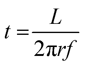 | (1) |
Ex situ film thickness measurements
The film thicknesses were determined ex situ using a Horiba Jobin Yvon spectroscopic ellipsometer. Due to the limited stability of the alucone films in the ambient atmosphere,15 the measurements were performed within 15 min after deposition. The film thicknesses were extracted using a Cauchy model in a spectral range of 1–3.5 eV. A 3 layer stack was used with Si substrate as the bottom, a native SiO2 of 2 nm as the middle and the alucone film as the top layer.Results and discussion
At fixed partial pressures of TMA and EG of 1.05 Torr and 0.5 Torr respectively and a fixed timing sequence of (0.77, 8.4, 0.77, 2), Fig. 2a shows the film thickness as a function of the number of MLD cycles. Similar to an ALD process, the thickness increases linearly with the number of cycles with a growth per cycle of 0.36 nm per cycle. Also observed is that the linear fit does not pass through the origin but has an x-intercept of approximately 8 cycles.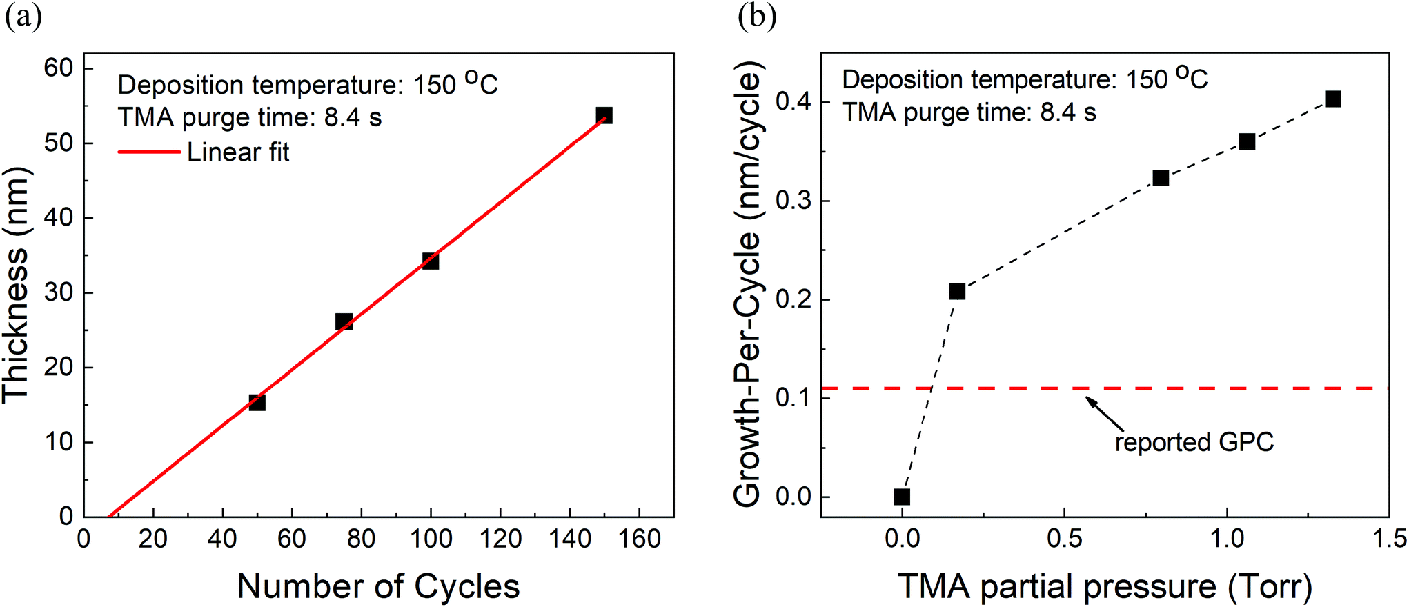 | ||
| Fig. 2 (a) Measured film thickness vs. the number of cycles. The GPC is ∼0.36 nm per cycle with an x-intercept of 8 cycles. (b) Growth-per-cycle vs. the partial pressure of TMA. In these experiments, the partial pressure of EG was kept constant at 0.5 Torr and a timing sequence of (0.77, 8.4, 0.77, 2) was used. The GPC shows no signs of saturation and even at the lowest TMA partial pressure of 0.17 Torr, it is already higher than previously reported GPC.15 | ||
Furthermore, at a constant EG partial pressure of ∼0.5 Torr and a timing sequence of (0.77, 8.4, 0.77, 2), Fig. 2b shows the variation of GPC with respect to the partial pressure of TMA. Unlike a typical ALD process, the GPC shows no signs of saturation. However, in literature, the GPC for this process has been reported to be around 0.11 nm per cycle at 150 °C.15 It can be observed in Fig. 2b that even at the lowest TMA partial pressure used of 0.17 Torr, the GPC is much higher than 0.11 nm per cycle. The GPC reported in the literature was, however, obtained by using a very long purge time of 120 s for both TMA and EG. In comparison, the purge times used in Fig. 2b are 8.4 s and 2 s for TMA and EG respectively.
In the case of hybrid alucone/alkoxide films prepared using TMA, it has been previously reported that the films are porous39 and during its dose, TMA not only participates in the surface reactions but also infiltrates into the underlying film.15,37,38,45 Most of these reports are based on the observation that the initial increase in the mass detected by a quartz crystal microbalance (QCM) during TMA's dose step is much higher than what is required to saturate surface reactions. During the subsequent purge, most of the excess mass is reduced to a non-zero steady-state value close to the mass needed to saturate the surface reactions. Similar behavior has also been observed in the case of metalcone films prepared using other precursors like titanium tetrachloride (TiCl4)46 and diethyl zinc (DEZ).47 However, in some cases, part of the infiltrated precursor has been observed to stay permanently trapped within the film and hence, even after very long purge steps, the steady-state mass gain/cycle value was several times higher than needed for surface saturation.45
In contrast, such infiltration effects have not been observed for organic co-reactants. As observed by Dameron et al., the QCM data shows no decrease in mass during the EG purge step of the alucone (TMA + EG) deposition process.15 This might indicate that, unlike TMA, the amount of EG infiltration is small. The reason for this could originate from a very low diffusion coefficient of EG or low solubility of EG in the alucone film. Another possible explanation behind this observation could be that some of the infiltrated TMA stays permanently trapped within the film and during EG's dose, just enough EG might infiltrate into the film to react with the trapped yet unreacted TMA still leading to a non-decaying QCM signal during EG's purge step. Lee et al. also observed no excess mass gain during the glycidol dose in depositions carried out using TMA + glycidol.37 In the case of a hybrid film grown using 3 step ABC scheme of TMA, ethanolamine and maleic anhydride, Seghete et al. reported seeing no mass decrease during the ethanolamine and maleic anhydride purging steps.45 Similarly, Abdulagatov et al. also observed no decrease in mass gain during EG purge time in the growth of titanicone (TiCl4 + EG) films.46 However, surface adsorption of EG has been reported by Peng et al. in a zincone (DEZ + EG) deposition process at 120 °C.36 The adsorption happened over a long EG exposure step of 4 s and led to very small excess mass gains that decreased during the subsequent purge step. Thus, unlike purge steps of precursors like TMA and DEZ, purge steps of typical MLD co-reactants like EG are less likely to influence the MLD deposition process.
If the provided purge time is insufficient for the infiltrated TMA to diffuse out of the film, the outgassing of TMA will continue into the EG exposure step thereby leading to CVD-type reactions alongside surface MLD reactions. In such a case, the total growth-per-cycle (ΓTotal) would be a combination of contributions from CVD-type reactions (ΓCVD) and MLD reactions (ΓMLD) as shown in Fig. 3. The continuous increase in GPC previously seen in Fig. 2b can be attributed to an increase in the amount of TMA that infiltrates into the film with increasing partial pressure. For an insufficient purge time, this would directly correlate to an increase in the amount of outgassing TMA's flux and an increase in the CVD contributions.
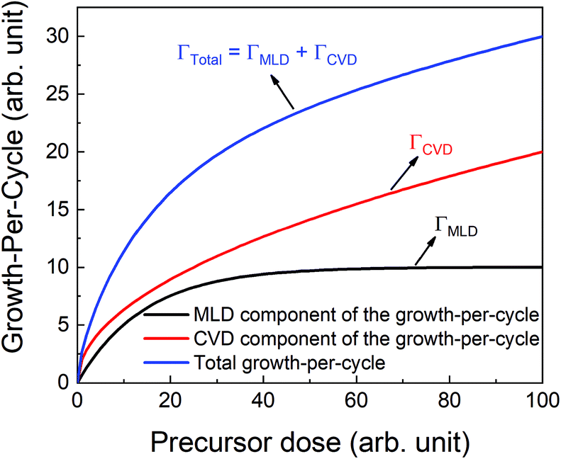 | ||
| Fig. 3 A schematic showing different contributions in the total growth-per-cycle. The total GPC (ΓTotal) could be seen as a result of contributions from the surface MLD reactions (ΓMLD) and the CVD reactions (ΓCVD). | ||
We have also investigated the effect of purge time after TMA dose on the total growth-per-cycle (ΓTotal) as shown in Fig. 4. The effect was evaluated for each of the four different TMA partial pressures in Fig. 2b while using a constant EG partial pressure of 0.5 Torr and a timing sequence of (0.77, X, 0.77, 2) where X denotes the purge time after TMA dose which was systematically varied from 8.4 to 98.4 s. All depositions were performed at 150 °C. For all partial pressures of TMA and with increasing TMA purge time, ΓTotal appears to decrease exponentially to reach a steady-state value for long purge times. It can be understood that, with increasing purge time, the amount of outgassing TMA decreases as the alucone film becomes increasingly depleted of TMA thereby leading to a decreasing CVD contribution and a lower ΓTotal. For long enough purge times, the amount of outgassing TMA becomes negligible and ΓTotal reaches a steady-state value where it has contributions only from the MLD surface reactions. The purge times required to reach these steady-state values are 1–2 orders of magnitude longer than the exposure times. It can also be seen in Fig. 4 that for an insufficient purge time, ΓTotal increases with the increasing partial pressure of TMA. A higher TMA partial pressure means more infiltration of TMA followed by a larger amount of outgassing TMA which for an insufficient purge would increase the CVD contribution in the overall growth and lead to an increase in ΓTotal. Also, the purge time required to reach the steady-state GPC increases accordingly with TMA partial pressure.
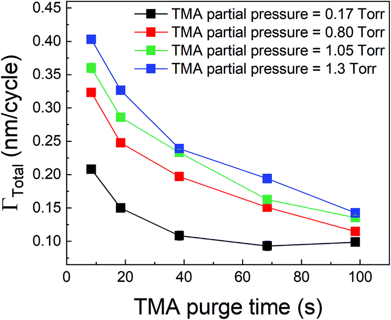 | ||
| Fig. 4 Γ Total as a function of TMA purge time. In these experiments conducted at 150 °C, the EG dose, its purge time and TMA exposure time were kept constant while the TMA purge time was varied. For each TMA partial pressure, ΓTotal decreases with increasing TMA purge time and upon a long enough purge stabilizes at a steady-state value equal to ΓMLD. | ||
At the onset of the film growth process, the alucone film is thin enough for all of the infiltrated TMA to purge out of the film in the given purge time. This means that the CVD component will be negligible and the film will only grow by the virtue of surface MLD reactions. With increasing film thickness, the TMA infiltration depth can increase accordingly. If the provided purge time then becomes insufficient to remove the infiltrated TMA out of the film, the CVD reactions between the outgassing TMA and EG will also start to contribute to the total growth. When the film thickness exceeds the TMA diffusion length, the amount of outgassing TMA is no longer determined by the film thickness but by TMA purge time. The infiltration-outgassing process then reaches an equilibrium and the CVD contribution to ΓTotal becomes constant with the number of cycles as observed in Fig. 2a. In case the value of ΓCVD is substantial, a linear fit of ΓTotal would lead to an apparent non-zero x-intercept, indicative of the cycle number where the CVD contributions become significant and corresponding to when the film thickness starts to exceed the diffusion length.
Kinetic model for the CVD component
Based on the observations before, we propose a phenomenological kinetic model for the CVD component (ΓCVD) of the growth-per-cycle. A general equation for the reaction rate R between the outgassing TMA and EG during the EG exposure is given by:| R = k[TMA]a[EG]b | (2) |
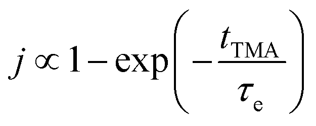
The concentration of TMA at the film surface after a purge time tp can be assumed to be proportional to its outgassing flux. Furthermore, this outgassing flux would depend upon the exposure and purge steps of TMA. The solution for the flux of an outgassing species from a plane sheet of finite thickness has been provided by Crank.48 For a TMA diffusion coefficient (D) and the MLD film's thickness (h), the solution for the outgassing flux (j) after a TMA purge time (tp) is given by,
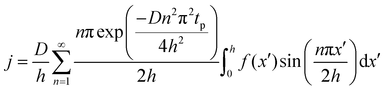 | (3) |
| Short TMA exposure time
|
Long TMA exposure time
|
|
|---|---|---|
Short TMA purge time 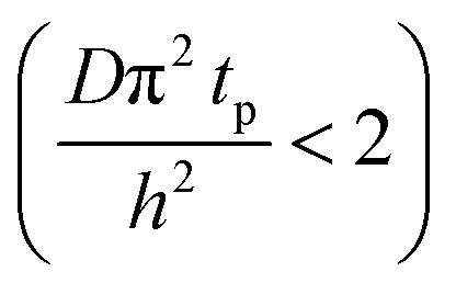 |
j ∝ S PTMA | j ∝ S PTMA |

|
|
|
|
||
Long TMA purge time  |
j ∝ S PTMA | j ∝ S PTMA |
|
|
|
|
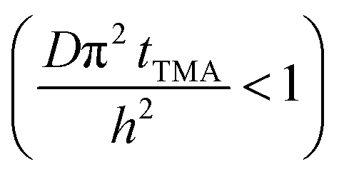
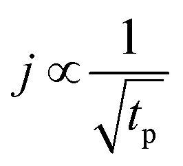
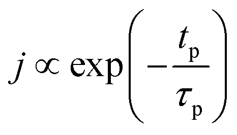
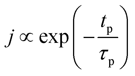
The experimental conditions used in this study correspond to the case of a short exposure  and short purge time
  regimes. Therefore,
 | (4) |
On the other hand, the concentration of EG at the film surface can be assumed to be proportional to its partial pressure:
| [EG] ∝ PEG | (5) |
Substituting eqn (4) and (5) into eqn (2) gives,
 | (6) |
The CVD growth-per-cycle (ΓCVD) will be proportional to the total reaction products generated during the EG exposure step (tEG). In other words, ΓCVD will be proportional to the integral of eqn (6) for t = tp to t = tp + tEG:
 | (7) |
Since EG is being constantly replenished in its reactant zone, we can assume that  . Also, for short EG exposure times (tEG ≪ tp), we can assume that the outgassing TMA's flux is constant during the entire EG exposure step. Hence, the integral in eqn (7) can be solved simply giving,
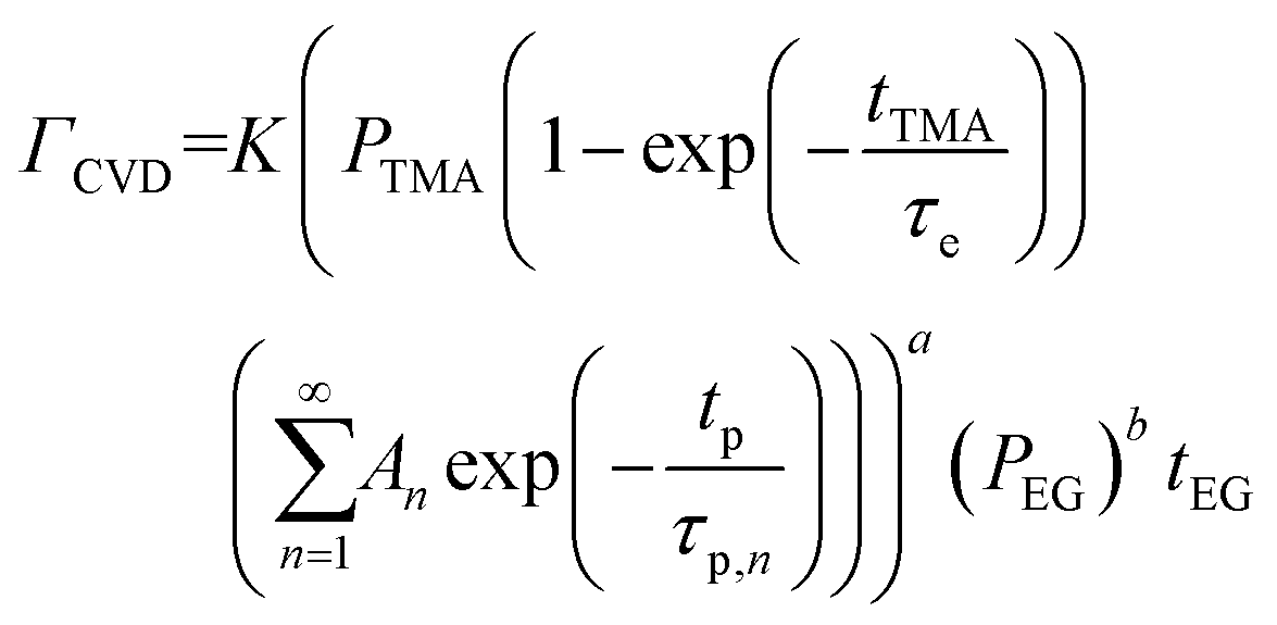 | (8) |
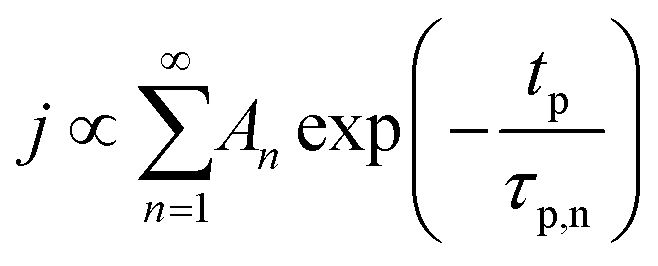
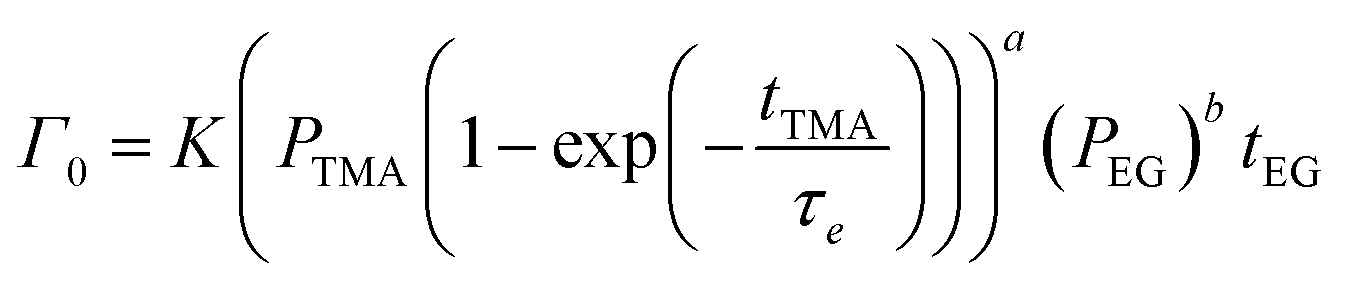
At a given deposition temperature and given exposure times and partial pressures of TMA and EG, the ΓCVD as a function of TMA purge time can be simplified by reducing eqn (8) into
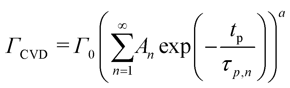 | (9) |
 | (10) |
The ΓCVD contributions along with ΓMLD lead to the total growth-per-cycle (ΓTotal). Therefore,
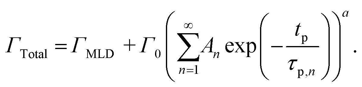 | (11) |
Experimental verification of the model
We have used the experimental data in Fig. 4 to verify our model. Since the only process parameter varied in Fig. 4 is the TMA purge time, we have used eqn (11) for fitting. It was observed that the variation at each partial pressure of TMA could be fitted satisfactorily using only the first term of the summation (n = 1) and the terms for (n > 1) become redundant. Hence, eqn (11) can be simplified to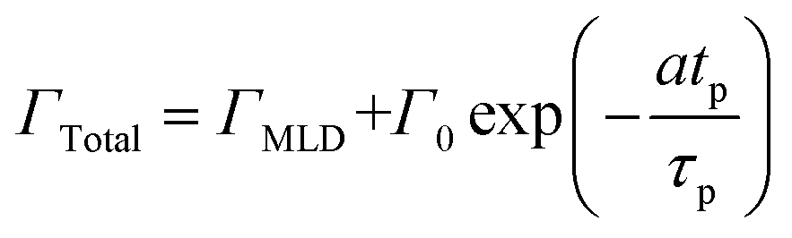 | (12) |
The fitting results are elaborated in the ESI's section B† and the extracted values of the model parameters are shown in Table 2.
| TMA partial pressure (Torr) | Γ MLD (nm per cycle) | Γ 0 (nm per cycle) |
|
|---|---|---|---|
| 0.17 | 0.09 ± 0.01 | 0.18 ± 0.03 | 17 ± 4 |
| 0.80 | 0.11 ± 0.03 | 0.26 ± 0.03 | 33 ± 11 |
| 1.05 | 0.11 ± 0.02 | 0.29 ± 0.02 | 43 ± 10 |
| 1.33 | 0.13 ± 0.02 | 0.34 ± 0.02 | 35 ± 9 |
Fig. 5a shows the values of ΓMLDvs. the corresponding TMA partial pressure. The saturating behavior of ΓMLD is quite evident where it saturates around 0.11–0.12 nm per cycle. This value is very close to the value reported in literature obtained on a conventional ALD tool using long TMA purge times of 120 s.15
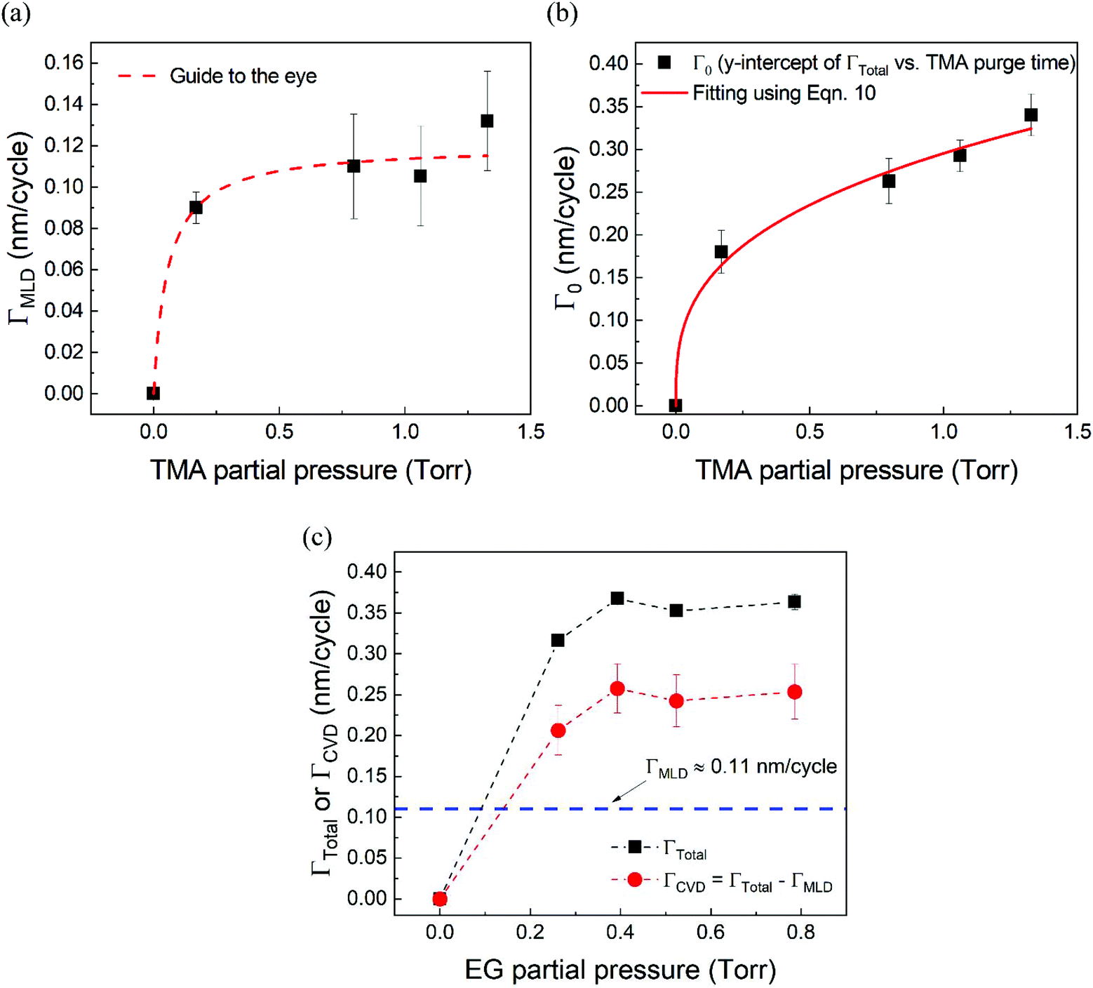 | ||
| Fig. 5 (a) ΓMLD as extracted by the model vs. TMA partial pressure at 150 °C. Unlike ΓTotal in Fig. 2b, ΓMLD shows a soft saturation with the increasing TMA partial pressure around 0.12 nm per cycle. (b) Variation of Γ0 with TMA partial pressure. These datapoints were extracted by fitting the data shown in Fig. 4 with the proposed model. A fit based on eqn (10) has been used to determine TMA's partial order of reaction a which equals 0.38 ± 0.05. (c) ΓCVDversus EG partial pressure. In these experiments, only the partial pressure of EG was varied while keeping the partial pressure of TMA constant at ∼1 Torr and the timing sequence constant at (0.77, 8.4, 0.77, 2). Compared to the effect of TMA partial pressure, the effect of EG partial pressure on CVD contributions is negligible. | ||
Fig. 5b shows the dependence of Γ0 on the partial pressure of TMA. As can be seen from eqn (10), Γ0 is directly proportional to the partial pressure of TMA indicative of the fact that the amount of TMA that infiltrates into the film increases with the increasing TMA partial pressure. The same is observed in Fig. 5b where the value of Γ0 increases with TMA partial pressure and shows no signs of saturation. Fitting the data in Fig. 5b with eqn. (10) results in the TMA partial order of reaction (a) value of 0.38 ± 0.05. It can also be seen that the partial pressure of TMA has a much stronger impact on ΓCVD than ΓMLD. In other words, the CVD component can be reduced significantly without impacting ΓMLD by decreasing the partial pressure of TMA.
Similarly, in order to see the effect of the partial pressure of EG on ΓCVD, we have plotted the variation of observed ΓCVD with the EG partial pressure in Fig. 5c. In these depositions, the partial pressure of TMA was kept constant at 1.05 Torr and the timing sequence used was (0.77, 8.5, 0.77, 2). Though varied, the partial pressure of EG was kept high enough to saturate the MLD surface reactions. Hence, any changes in ΓTotal can be attributed to changes in ΓCVD. Furthermore, ΓCVD can be simply calculated by subtracting ΓMLD (0.11 nm per cycle) from ΓTotal. Unlike the variation of ΓTotal with respect to the partial pressure of TMA as seen in Fig. 2b, it can be seen in Fig. 5c that ΓCVD does not vary much with the partial pressure of EG. This is understandable as the CVD reactions happen during the EG exposure step where the surface concentration of EG is probably in excess compared to the surface concentration of the outgassing TMA after its long purge step. Similar results were observed when using a higher TMA partial pressure of 1.33 Torr.
From Table 2, it can also be seen that the value of time constant τp stays relatively constant at higher TMA partial pressures but decreases for the lowest partial pressure of 0.17 Torr. This could be explained by some fraction of the infiltrated TMA that gets permanently trapped within the film, reducing the amount of TMA available for outgassing. This reduction is more prominent at low partial pressures of TMA and decreases the value of τp.
In summary, in order to minimize the CVD contributions, the partial pressure of TMA should be kept as low as possible and long enough TMA purge times should be used. It is important to understand that the partial pressures of TMA and EG described in the model are the partial pressure values at the surface of the film, which are not necessarily the same as the partial pressures at the reactor inlet. The surface partial pressure of a reactant is determined by the balance between the reaction rate and reactant transport in the gas phase by diffusion and convection. Similarly, during TMA's purge step, the outgassing rate of TMA from the film's bulk could be dependent on the removal of the already outgassed TMA above the film surface. If the removal is inefficient, the consequent outgassing from the film's bulk could be expected to be slower as well. Especially in atmospheric pressure ALD, diffusion of reactants through a boundary layer has been shown to be important34,49 and its role in the kinetics of the CVD component as described above would require further investigation.
We have also studied the effect of deposition temperature on the decrease in ΓTotal with respect to TMA purge time. In these experiments, the partial pressures of TMA and EG were fixed at 1.05 Torr and 0.5 Torr respectively. The timing sequence used was (0.77, X, 0.77, 2) where X being TMA purge time was systematically varied from 8.4 s to 98.4 s. This was repeated at three different deposition temperatures. Fig. 6 shows that ΓTotal decreases with increasing TMA purge time at all temperatures. By fitting each of these curves with eqn (12) of the model, we have extracted the values of ΓMLD, Γ0 and the time constant τp at each temperature as shown in Table 3. The fitting results are shown in the ESI's section B.†
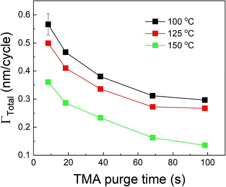 | ||
| Fig. 6 Effect of deposition temperature on the decrease of ΓTotal with TMA purge time. | ||
| Deposition temperature (°C) | Γ MLD (nm per cycle) | Γ 0 (nm per cycle) | τ p (s) |
|---|---|---|---|
| 100 | 0.30 ± 0.01 | 0.39 ± 0.05 | 9 ± 2 |
| 125 | 0.23 ± 0.03 | 0.33 ± 0.03 | 13 ± 5 |
| 150 | 0.11 ± 0.02 | 0.29 ± 0.02 | 16 ± 4 |
As seen in Table 3, ΓMLD decreases with increasing deposition temperature and the corresponding values are close to those observed by Dameron et al.15 The decrease in ΓMLD with deposition temperature is in agreement with what has been observed in the growth of several hybrid films and could be due to a decrease in the number of available reactive surface sites with temperature.11 Moreover, Γ0 also decreases with increasing temperature. A reduction in the amount of infiltration of TMA into MLD films at higher temperatures has been reported previously37,45 and corresponds well to our observed decreasing trend of Γ0. An increase in the film's density with temperature could result in a decrease in the infiltration of TMA and can explain this observation, but the density of alucone films has been reported to stay constant within a temperature range of 85–175 °C.15 One of the possible explanations for the decrease in Γ0 could be a decrease in the solubility of TMA within the polymeric film.44 For example, Sinha et al. also observed a decrease in the solubility of water and titanium isopropoxide in PMMA films with increasing temperature.50 Further, an Arrhenius plot between ln![[thin space (1/6-em)]](https://www.rsc.org/images/entities/char_2009.gif) Γ0 and 1/T shows a linear relationship. A linear regression (see ESI's section C†) of the variation gives an activation energy of −6.88 kJ mol−1 and a y-intercept of −3.19 nm per cycle. The negative activation energy observed here cannot be interpreted as the energy barrier for TMA dissolution but instead could be indicative of a negative heat of sorption for TMA in the alucone films similar to what has been reported by Sinha et al. in the cases of water and titanium isopropoxide dissolution in PMMA.50 Another possible explanation for the decrease in Γ0 with increasing deposition temperature could be an increase in the desorption rate of the surface-adsorbed TMA thereby reducing the amount of TMA available to dissolve in the polymeric film.
Γ0 and 1/T shows a linear relationship. A linear regression (see ESI's section C†) of the variation gives an activation energy of −6.88 kJ mol−1 and a y-intercept of −3.19 nm per cycle. The negative activation energy observed here cannot be interpreted as the energy barrier for TMA dissolution but instead could be indicative of a negative heat of sorption for TMA in the alucone films similar to what has been reported by Sinha et al. in the cases of water and titanium isopropoxide dissolution in PMMA.50 Another possible explanation for the decrease in Γ0 with increasing deposition temperature could be an increase in the desorption rate of the surface-adsorbed TMA thereby reducing the amount of TMA available to dissolve in the polymeric film.
From Table 3 it can also be observed that the time constant τp shows a slightly increasing trend with temperature. An Arrhenius plot between lnτp and 1/T is shown in the ESI's section C.† From the data, an activation energy of 10.97 kJ mol−1 and a y-intercept of 5.9 s could be extracted. The value of τp depends not only on the diffusion coefficient of TMA but also on the ability of TMA to desorb from the film's bulk and its surface. With increasing temperature, the infiltrated TMA species are more likely to desorb from the film's bulk and consequently, a higher fraction of infiltrated TMA would become available to outgas. This can mean that the TMA would outgas for a longer period of time and can explain the slight increase in the value of τp with temperature. Similar observations have been reported in other hybrid films (TMA + glycidol) where after deposition, the films showed a mass decrease in QCM for extended periods (20 min) at higher temperatures (>125 °C).
Discussion
From all the above observations, it is clear that the purge time after the TMA exposure is of paramount importance in determining the amount of CVD component in the overall growth per cycle. When minimizing the CVD component, the long TMA purge times will dominate the overall cycle time and therefore the deposition rate. Furthermore, a large CVD component can have undesirable effects on film properties and step coverage. There are several options to reduce the impact of TMA infiltration, e.g. by reducing the amount of TMA that infiltrates or by increasing the outgassing rate.As shown before, the amount of TMA that infiltrates in the underlying film depends on the TMA partial pressure. By reducing the TMA partial pressure, the required purge time to minimize the CVD contributions should also reduce. Fig. 7 for example, shows the deposition rate as a function of TMA partial pressure, calculated by dividing the total growth per cycle (ΓTotal) by the cycle time for the case that the CVD contribution is small, i.e. 10% of ΓMLD. In this calculation, the value of τp for all TMA partial pressures has been assumed to be constant and equal to the mean of its values observed at high TMA partial pressures (>0.8 Torr) shown in Table 2. It can be seen that the deposition rate can be increased by up to 25% by reducing the TMA partial pressure.
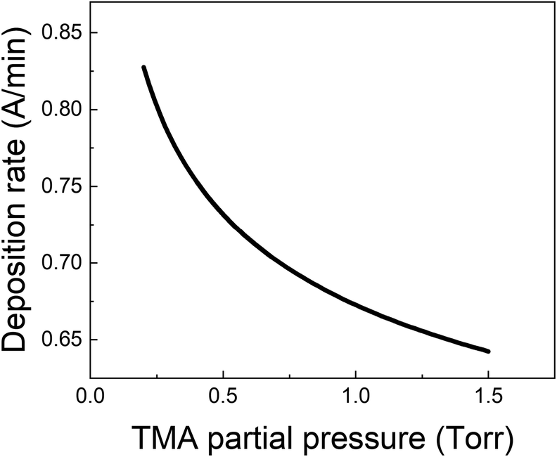 | ||
| Fig. 7 Deposition rate as a function of TMA partial pressure for the case that the CVD contribution is small i.e. ΓCVD = 0.1 ΓMLD. | ||
Other strategies to increase the deposition rate can include increasing the efficiency of the purging step by increasing the purge gas flow rate.36,49 Increasing the purge gas flow rate could result in quicker removal of the desorbed TMA and consequently, more TMA can desorb from the surface. In our experimental setup, the role of purge gas is played by the N2 flow through the inert gas curtains. Hence, we have investigated the effect of N2 flow rate through these curtains on ΓTotal as shown in Fig. 8 where the partial pressures of TMA and EG were kept constant at 1.05 Torr and 0.5 Torr respectively and a timing sequence of (0.77, 8.4, 0.77, 2) was used. It can indeed be observed that ΓTotal slightly decreases with increasing purge gas flow rate.
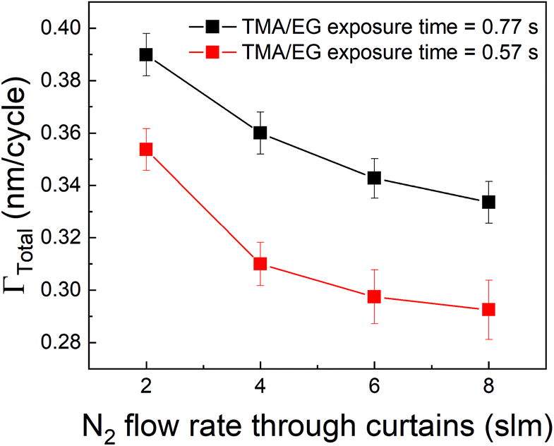 | ||
| Fig. 8 Γ Total as a function of N2 flow through the gas curtains. In these experiments, the partial pressures and exposure times of both TMA and EG were kept constant while only the N2 flow through the four curtains was varied from 2 to 8 slm (0.5 to 4 slm per curtain). | ||
A different approach to minimize the purge time could be a different choice of the precursor. In vapor-phase infiltration kinetics, it is known that the size and shape of the infiltrating species can have a very strong effect on their dissolution and diffusion within polymers.44 The same can be expected in the case of an alucone film. If an aluminum precursor with a larger molecular size than TMA could be used, the amount of infiltration might get reduced. An example of a bulkier aluminum precursor is DMAI (dimethylaluminum isopropoxide). To investigate the effect of precursor molecule size on infiltration and outgassing, we have performed some initial experiments where DMAI was used as a precursor instead of TMA to deposit alucone films. To our knowledge, this is the first example of using DMAI as a precursor for MLD of alucone. The experimental details can be found in the ESI's section D.† As demonstrated in ALD of Al2O3, DMAI has a lower reactivity and vapor pressure than TMA,51 meaning that, to reach saturation in the MLD contribution (ΓMLD), a significantly longer DMAI exposure time is required than when using TMA. This combined with the fact that alucone films made with DMAI seem to have a lower GPC than when TMA is used, it would seem not beneficial to use DMAI as a precursor to achieve a high deposition rate. Fig. 9 shows ΓTotalvs. the DMAI purge time, similar to Fig. 4, for two different DMAI exposure times. It can be clearly seen that the ΓTotal is much smaller as compared to the TMA case, and does not significantly vary with purge time. This is indicative of the fact that DMAI does not outgas from the film as observed with TMA, most likely because the larger DMAI molecule does not infiltrate in the first place. However, other factors like lower solubility of DMAI in the alucone films and a lower sticking coefficient could also mean that less DMAI is available at the film's surface to diffuse into the film's bulk leading to very less infiltration. Nevertheless, the fact that a much shorter purge time can be used as compared to TMA translates into a deposition rate of 6 Å min−1, one order of magnitude higher than for TMA, even though the reactivity and GPC of DMAI is lower than for TMA. A more detailed investigation into the MLD of alucone using DMAI is ongoing, but it can already be concluded that at least in terms of the deposition rate, the choice of precursor, its dose and the purge step are of at least equal importance in MLD of alucone films than the choice and dose of organic co-reactant. The same strategy can be employed by changing the organic coreactant. Co-reactants like glycerol (GL) when combined with TMA have been shown to produce alucone films with a cross-linked architecture. When compared to the TMA + EG process, the growth process showed a smaller variation in GPC with deposition temperature and this was attributed to a lower extent of TMA infiltration due to the cross-linked architecture of the film.52 The TMA + GL films also showed higher stability in ambient atmosphere and a higher critical tensile strain of cracking than TMA + EG films. However, Kerckhove et al. observed that using glycerol in the alucone MLD could lead to films with lower carbon content than the ones produced using ethylene glycol.53 If this change in the film's composition can be tolerated, it is indeed beneficial to use co-reactants like glycerol for alucone MLD.
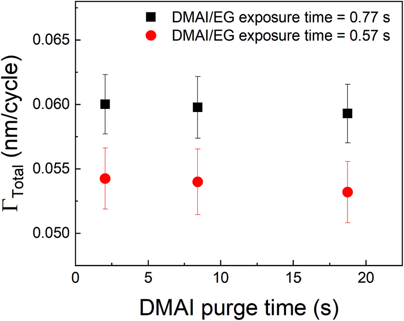 | ||
| Fig. 9 Γ Total as a function of DMAI purge time. Unlike the observed decrease in ΓTotal with respect to TMA purge time, the DMAI purge time seems to have a negligible effect on ΓTotal. | ||
Conclusions
It can be concluded that in the deposition of alucone films using TMA and EG, the purge time after TMA is of paramount importance to the deposition rate. Along with its participation in the surface MLD reactions, TMA is also seen to infiltrate into the underlying film and takes very long to diffuse out completely. In the case of an insufficient purge time before the EG dose, TMA will still outgas during the EG dose leading to a CVD contribution in the overall film growth. Due to this, the GPC as a function of TMA partial pressure was observed to show no signs of saturation. Such a CVD component might be undesirable as it can have a negative impact on the film properties and step coverage. Preventing the CVD component would then require very long purge times, significantly reducing the deposition rate. On the other hand, the CVD component might not alter the film properties at all but instead, can provide a very high deposition rate. Hence, in order to understand and potentially optimize the effect of TMA purge time, a phenomenological kinetic model was developed that describes the total GPC as a combination of its MLD and CVD components.We were able to experimentally verify the model dependence on TMA purge time, partial pressures of TMA and EG and the deposition temperature. As is predicted by the model, the CVD contribution was observed to decrease exponentially with TMA purge time and for long enough purges (>100 s) becomes negligible. The CVD component was also observed to decrease with decreasing partial pressure of TMA. On the contrary, it was found that the partial pressure of EG had a negligible impact on the CVD component. With deposition temperature, both the CVD and MLD components decreased with increasing temperature. Also, the outgassing of TMA was observed to be slightly faster at lower deposition temperatures.
In summary, if a CVD component cannot be tolerated in the film growth process, it is advisable to use low partial pressure of TMA and low temperatures to achieve high deposition rates. If on the other hand, a CVD component can be tolerated, it is still advisable to use low temperatures due to high GPC but alongside short TMA purge times and high partial pressures of TMA. Such insights into the kinetics of the growth process can eventually be used in designing appropriate MLD reactors and choosing the most efficient process parameters. As an attempt to mitigate the problem of precursor infiltration, we have also investigated the use of a bulkier precursor like dimethylaluminum isopropoxide (DMAI) instead of TMA and found that the bulkier substitutes like DMAI can indeed help in mitigating the problem of precursor infiltration and increase the deposition rate of alucone films by an order of magnitude. However, the compositional properties of the alucone films prepared using the substitutes need to be investigated in detail and compared with those of TMA + EG films. It also remains to be seen how the observed impact of TMA purge time and the use of DMAI will affect the conformality and uniformity in thickness on 3D substrates where not only the diffusion of TMA/DMAI within the alucone film will play a role but also diffusion of reactants into the 3D architecture.
Although this work focused on MLD of alucone films, we believe its findings and conclusions are relevant for many other MLD systems. While many MLD systems suffer from low deposition rates that limit their potential for use in new applications, we believe this work can help to give directions in optimizing the already created deposition recipes and in developing new MLD precursors, processes and equipment for low-cost and high-throughput applications.
Abbreviations
| ALD | Atomic layer deposition |
| MLD | Molecular layer deposition |
| CVD | Chemical vapor deposition |
| VPI | Vapor phase infiltration |
| GPC | Growth-per-cycle |
| TMA | Trimethylaluminum |
| EG | Ethylene glycol |
| QCM | Quartz crystal microbalance |
| DEZ | Diethyl zinc |
| DMAI | Dimethylaluminum isopropoxide |
Funding Sources
This project has received funding from the European Union's Horizon 2020 research and innovation programme under the Marie Skłodowska-Curie grant agreement no 765378.Conflicts of interest
There are no conflicts of interest to declare.Acknowledgements
This project has received funding from the European Union's Horizon 2020 research and innovation programme under the Marie Skłodowska-Curie grant agreement no 765378. The authors thank Prof. Mariadriana Creatore of the Applied Physics department of TU Eindhoven and Dr Fieke van den Bruele of Holst Center, Eindhoven for critical discussions. The authors also thank Frank Grob and Willem van Boekel of Holst Center, Eindhoven for technical assistance.References
- J. A. van Delft, D. Garcia-Alonso and W. M. M. Kessels, Semicond. Sci. Technol., 2012, 27, 074002 CrossRef.
- Y. Y. Lin, C. C. Hsu, M. H. Tseng, J. J. Shyue and F. Y. Tsai, ACS Appl. Mater. Interfaces, 2015, 7, 22610–22617 CrossRef CAS PubMed.
- C. Marichy, M. Bechelany and N. Pinna, Adv. Mater., 2012, 24, 1017–1032 CrossRef CAS PubMed.
- J. Lu, J. W. Elam and P. C. Stair, Surf. Sci. Rep., 2016, 71, 410–472 CrossRef CAS.
- G. S. Higashi and C. G. Fleming, Appl. Phys. Lett., 1989, 55, 1963–1965 CrossRef CAS.
- M. Asif Khan, R. A. Skogman, J. M. Van Hove, D. T. Olson and J. N. Kuznia, Appl. Phys. Lett., 1992, 60, 1366–1368 CrossRef CAS.
- B. S. Lim, A. Rahtu and R. G. Gordon, Nat. Mater., 2003, 2, 749–754 CrossRef CAS PubMed.
- M. Junige and S. M. George, J. Vac. Sci. Technol., A, 2021, 39, 023204 CrossRef CAS.
- M. Putkonen, J. Harjuoja, T. Sajavaara and L. Niinistö, J. Mater. Chem., 2007, 17, 664–669 RSC.
- A. Kim, M. A. Filler, S. Kim and S. F. Bent, J. Am. Chem. Soc., 2005, 127, 6123–6132 CrossRef CAS PubMed.
- P. Sundberg and M. Karppinen, Beilstein J. Nanotechnol., 2014, 5, 1104–1136 CrossRef PubMed.
- K. Ashurbekova, K. Ashurbekova, I. Saric, M. Gobbi, E. Modin, A. Chuvilin, M. Petravic, I. Abdulagatov and M. Knez, Chem. Mater., 2021, 33, 1022–1030 CrossRef CAS.
- L. Svärd, M. Putkonen, E. Kenttä, T. Sajavaara, F. Krahl, M. Karppinen, K. Van De Kerckhove, C. Detavernier and P. Simell, Langmuir, 2017, 33, 9657–9665 CrossRef PubMed.
- I. Šarić, M. Kolympadi Markovic, R. Peter, P. Linić, K. Wittine, I. Kavre Piltaver, I. Jelovica Badovinac, D. Marković, M. Knez and G. Ambrožić, Appl. Surf. Sci., 2021, 539, 148254 CrossRef.
- A. A. Dameron, D. Seghete, B. B. Burton, S. D. Davidson, A. S. Cavanagh, J. A. Bertrand and S. M. George, Chem. Mater., 2008, 20, 3315–3326 CrossRef CAS.
- A. I. Abdulagatov, R. A. Hall, J. L. Sutherland, B. H. Lee, A. S. Cavanagh and S. M. George, Chem. Mater., 2012, 24, 2854–2863 CrossRef CAS.
- D. Choudhury, S. K. Sarkar and N. Mahuli, J. Vac. Sci. Technol., A, 2015, 33, 01A115 CrossRef.
- W. Zhou, J. Leem, I. Park, Y. Li, Z. Jin and Y. S. Min, J. Mater. Chem., 2012, 22, 23935–23943 RSC.
- O. Nilsen, K. Klepper, H. Nielsen and H. Fjellvaåg, ECS Trans., 2019, 16, 3–14 CrossRef.
- J. Kint, F. Mattelaer, S. S. T. Vandenbroucke, A. Muriqi, M. M. Minjauw, M. Nisula, P. M. Vereecken, M. Nolan, J. Dendooven and C. Detavernier, Chem. Mater., 2020, 32, 4451–4466 CrossRef CAS.
- G. Chen, Y. Weng, F. Sun, X. Zhou, C. Wu, Q. Yan, T. Guo and Y. Zhang, RSC Adv., 2019, 9, 20884–20891 RSC.
- X. Yu, D. Bobb-Semple, I.-K. Oh, T.-L. Liu, R. G. Closser, W. Trevillyan and S. F. Bent, Chem. Mater., 2021, 33, 902–909 CrossRef CAS.
- B. Yoon, B. H. Lee and S. M. George, ECS Trans., 2019, 41, 271–277 CrossRef.
- S. H. Cha, A. Park, K. H. Lee, S. Im, B. H. Lee and M. M. Sung, Org. Electron., 2010, 11, 159–163 CrossRef CAS.
- K. S. Han, Y. Park, G. Han, B. H. Lee, K. H. Lee, D. H. Son, S. Im and M. M. Sung, J. Mater. Chem., 2012, 22, 19007–19013 RSC.
- E. Kazyak, M. Shin, W. S. Lepage, T. H. Cho and N. P. Dasgupta, Chem. Commun., 2020, 56, 15537–15540 RSC.
- D. M. Piper, J. J. Travis, M. Young, S. B. Son, S. C. Kim, K. H. Oh, S. M. George, C. Ban and S. H. Lee, Adv. Mater., 2014, 26, 1596–1601 CrossRef CAS PubMed.
- X. Li, A. Lushington, Q. Sun, W. Xiao, J. Liu, B. Wang, Y. Ye, K. Nie, Y. Hu, Q. Xiao, R. Li, J. Guo, T. K. Sham and X. Sun, Nano Lett., 2016, 16, 3545–3549 CrossRef CAS PubMed.
- Y. Zhao and X. Sun, ACS Energy Lett., 2018, 3, 899–914 CrossRef CAS.
- M. Yu, H. H. Funke, R. D. Noble and J. L. Falconer, J. Am. Chem. Soc., 2011, 133, 1748–1750 CrossRef CAS PubMed.
- P. Poodt, A. Lankhorst, F. Roozeboom, K. Spee, D. Maas and A. Vermeer, Adv. Mater., 2010, 22, 3564–3567 CrossRef CAS PubMed.
- D. H. Levy, D. Freeman, S. F. Nelson, P. J. Cowdery-Corvan and L. M. Irving, Appl. Phys. Lett., 2008, 92, 2006–2009 CrossRef.
- K. Sharma, R. A. Hall and S. M. George, J. Vac. Sci. Technol., A, 2015, 33, 01A132 CrossRef.
- P. Poodt, J. van Lieshout, A. Illiberi, R. Knaapen, F. Roozeboom and A. van Asten, J. Vac. Sci. Technol., A, 2013, 31, 01A108 CrossRef.
- S. Kim, S. Lee, S. Y. Ham, D. H. Ko, S. Shin, Z. Jin and Y. S. Min, Appl. Surf. Sci., 2019, 469, 804–810 CrossRef CAS.
- Q. Peng, B. Gong, R. M. VanGundy and G. N. Parsons, Chem. Mater., 2009, 21, 820–830 CrossRef CAS.
- Y. Lee, B. Yoon, A. S. Cavanagh and S. M. George, Langmuir, 2011, 27, 15155–15164 CrossRef CAS PubMed.
- B. Gong, Q. Peng and G. N. Parsons, J. Phys. Chem. B, 2011, 115, 5930–5938 CrossRef CAS PubMed.
- A. Perrotta, P. Poodt, F. J. Fieke Van Den Bruele, W. M. M. Erwin Kessels and M. Creatore, Dalton Trans., 2018, 47, 7649–7655 RSC.
- M. Knez, Semicond. Sci. Technol., 2012, 27, 074001 CrossRef.
- C. A. Wilson, R. K. Grubbs and S. M. George, Chem. Mater., 2005, 17, 5625–5634 CrossRef CAS.
- J. W. Elam, M. Biswas, S. Darling, A. Yanguas-Gil, J. D. Emery, A. B. F. Martinson, P. F. Nealey, T. Segal-Peretz, Q. Peng, J. Winterstein, J. A. Liddle and Y.-C. Tseng, ECS Trans., 2015, 69, 147–157 CrossRef CAS PubMed.
- J. W. Elam, C. A. Wilson, M. Schuisky, Z. A. Sechrist and S. M. George, J. Vac. Sci. Technol., B: Microelectron. Nanometer Struct.–Process., Meas., Phenom., 2003, 21, 1099 CrossRef CAS.
- C. Z. Leng and M. D. Losego, Mater. Horiz., 2017, 4, 747–771 RSC.
- D. Seghete, R. A. Hall, B. Yoon and S. M. George, Langmuir, 2010, 26, 19045–19051 CrossRef CAS PubMed.
- A. I. Abdulagatov, R. A. Hall, J. L. Sutherland, B. H. Lee, A. S. Cavanagh and S. M. George, Chem. Mater., 2012, 24, 2854–2863 CrossRef CAS.
- B. Yoon, J. L. O'Patchen, D. Seghete, A. S. Cavanagh and S. M. George, Chem. Vap. Deposition, 2009, 15, 112–121 CrossRef CAS.
- J. Crank, The Mathematics of Diffusion, Clarendon Press, Oxford, 1975 Search PubMed.
- M. B. M. Mousa, C. J. Oldham, J. S. Jur and G. N. Parsons, J. Vac. Sci. Technol., A, 2012, 30, 01A155 CrossRef.
- A. Sinha, D. W. Hess and C. L. Henderson, J. Vac. Sci. Technol., B: Microelectron. Nanometer Struct.–Process., Meas., Phenom., 2007, 25, 1721 CrossRef CAS.
- S. E. Potts, G. Dingemans, C. Lachaud and W. M. M. Kessels, J. Vac. Sci. Technol., A, 2012, 30, 021505 CrossRef.
- S. M. George, B. H. Lee, B. Yoon, A. I. Abdulagatov and R. A. Hall, J. Nanosci. Nanotechnol., 2011, 11, 7948–7955 CrossRef CAS PubMed.
- K. Van De Kerckhove, M. K. S. Barr, L. Santinacci, P. M. Vereecken, J. Dendooven and C. Detavernier, Dalton Trans., 2018, 47, 5860–5870 RSC.
Footnote |
| † Electronic supplementary information (ESI) available: (A) Evaluating scaling laws for the outgassing TMA flux, (B) fitting results, (C) Arrhenius plots of Γ0 and τp, (D) experimental details for alucone films prepared using DMAI and EG. See DOI: 10.1039/d1dt00623a |
| This journal is © The Royal Society of Chemistry 2021 |