Charting the quantitative relationship between two-dimensional morphology parameters of polyamide membranes and synthesis conditions†
Hyosung
An
 ab,
John W.
Smith
a,
Wenxiang
Chen
ab,
Zihao
Ou
ab,
John W.
Smith
a,
Wenxiang
Chen
ab,
Zihao
Ou
 a and
Qian
Chen
 *abcd
*abcd
aDepartment of Materials Science and Engineering, University of Illinois at Urbana-Champaign, Urbana, Illinois 61801, USA. E-mail: qchen20@illinois.edu
bMaterials Research Laboratory, University of Illinois at Urbana-Champaign, Urbana, Illinois 61801, USA
cDepartment of Chemistry, University of Illinois at Urbana-Champaign, Urbana, Illinois 61801, USA
dBeckman Institute for Advanced Science and Technology, University of Illinois at Urbana-Champaign, Urbana, Illinois 61801, USA
First published on 23rd October 2019
Abstract
Polyamide membranes serve as the active layer in thin-film composites used for nanofiltration and reverse osmosis, and their surface morphology strongly impacts separation performance. However, because these surface morphologies are highly irregular and heterogeneous, linking morphology parameters to membrane synthesis conditions quantitatively is challenging. Here we utilize a quantitative morphometry approach, together with the surface feature classification scheme reported in our earlier work, to image and analyse the surface morphologies of polyamide membranes synthesized with a range of monomer concentrations. From transmission electron micrographs of polyamide membranes, we measure projected morphology parameters of “dome” and “dimple” crumples in the membrane, including surface curvature, Feret dimensions, thickness, circularity, perimeter, and area. All features except circularity, which remains constant, exhibit opposite trends when charted against the concentrations of m-phenylene diamine or trimesoyl chloride monomers used in synthesis suggesting competing roles of these two monomers in shaping crumples. Surprisingly, mathematical fittings (linear, logarithmic, or exponential) relate these morphology parameters quantitatively to the monomer concentration ratio, despite the apparent irregularity of crumples. Our highly quantitative approach sheds insight into predictive design of membrane materials with desirable properties.
Design, System, ApplicationPolyamide membranes have served as a standard active layer in thin-film composites used in the desalination industry for more than 30 years. However, because these membranes develop highly irregular surface features during synthesis, quantitative understanding of their synthesis–morphology relationship is limited, and efforts to achieve precise and rapid molecular separation have focused mainly on empirical engineering. Herein, we describe new avenues to quantify the complex morphology of polyamide membranes and thereby link their structure to synthesis conditions. We found that morphological parameters with respect to the monomer concentration ratio collapse onto unified curves: with an increasing amine to acyl chloride concentration ratio, crumple thickness, perimeter, and Feret distance increase and surface curvature decreases. Moreover, we demonstrated unified mathematical relationships to scale individual crumples as a function of morphological parameters across a wide range of reaction conditions. This report can help lay foundations for predictive design of advanced separation membranes, for capturing greenhouse gases, water treatment, and purification and recovery in pharmaceutical, petrochemical, and chemical industries. |
Introduction
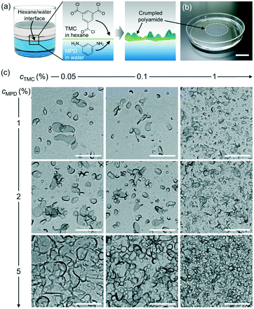
Thin-film composite (TFC) membranes have been widely used in the water desalination industry for more than three decades.1–3 TFC membranes generally consist of a polyester backing layer for physical support, a microporous polysulfone support midlayer, and a top layer of highly crosslinked and nanoporous polyamide membrane for selective molecular separation. The polyamide active layer is typically synthesized via polymerization at the interface of two immiscible phases: an aqueous phase containing an amine monomer and an organic phase containing an acyl chloride monomer (Fig. 1a). Upon contact of the two phases, the amine monomer in water can diffuse into the organic phase whereas the acyl chloride monomer is poorly soluble in water, so that polymerization occurs mostly on the organic side close to the water–organic interface.4–9 Subsequent polyamide film growth is self-limited because the diffusion of monomers is blocked by the grown film.6,8,9 This polymerization reaction is rapid (e.g., 50% of the final polyamide film forms within approximately 2 s)10 and highly exothermic, generating heat at the water–organic interface.11,12 The increase in temperature13 and other factors such as rapid diffusion of amines into the organic phase after formation of an incipient layer14 or generation of nanoscopic bubbles,12 are speculated to be the origins of irregular membrane morphologies, such as ridge-and-valley structures and crumples.13,15–17 For instance, polyamide films prepared by interfacial polymerization of trimesoyl chloride (TMC) and m-phenylene diamine (MPD) can exhibit a root-mean-square roughness as high as 80–120 nm due to crumple formation under certain synthesis conditions.18 These surface morphological features such as film roughness and thickness have been shown to impact the solvent permeability, mass transport, solute rejection of polyamide films,17,19,20 and sensitively depend on synthesis conditions such as monomer concentrations, support wettability, synthesis time, and temperature.1,8,13,20–25 For example, Xu et al. reported on the effects of monomer concentrations on morphology characteristics such as nodular or leaf-like features as well as the pore sizes of polyamide membranes by using scanning and transmission electron microscopy (SEM, TEM).26However, elucidating a quantitative and predictable, instead of empirical, relationship between the synthesis conditions and surface morphology of polyamide membranes remains challenging, despite its importance to the rational design of efficient membranes for various applications. Ensemble methods such as Rutherford backscattering spectroscopy,10,27–30 microfluidic interferometry,31 quartz crystal microbalance measurements,32–35 Fourier transform infrared mapping spectroscopy,36 time-domain thermoreflectance,32 and spectroscopic ellipsometry13,32,37 have been used to study polyamide membranes synthesized under different conditions, but cannot resolve their spatially irregular and heterogeneous surface morphology. For example, Matthews et al. used in situ diffuse reflectance and Rutherford Backscattering spectrometry to show the effects of monomer concentrations on polyamide growth kinetics and a relationship between the average roughness of the membrane and monomer concentration.10 Recent applications of direct imaging methods such as TEM tomography18,38,39 and focused ion beam SEM40 have resolved the internal and surface morphology of polyamide films, but did not provide a quantified relationship between the membrane morphology and the synthesis conditions.
Here we integrate TEM imaging with quantitative morphometry of polyamide membranes synthesized with the TMC and MPD concentrations systematically varied, to quantify synthesis–morphology relationships. We explicitly demonstrate that by increasing MPD monomer concentration, the morphological parameters of the crumples (surface curvature, Feret distance, thickness, perimeter, and area) are monotonically changed over a wide range. By increasing TMC monomer concentration, however, these morphological parameters are tuned in the opposite way. Interestingly, comparing the concentration ratio of MPD to TMC to these morphology parameters produces unified curves following either linear or exponential trends. The nanoscopic morphological parameters of individual crumples are macroscopically controlled as a function of synthesis conditions, which can potentially guide predictive design of polyamide membranes.
Experimental
Materials
Cadmium chloride hydrate (99.998%, CdCl2·xH2O, x ≈ 2.5, Alfa Aesar), ethanolamine (>98%, Sigma-Aldrich), m-phenylenediamine (MPD, 99%, Sigma-Aldrich), 1,3,5-benzenetricarbonyl trichloride (a.k.a. trimesoyl chloride, TMC, 98%, Sigma-Aldrich), molecular sieves (3 Å, 1–2 mm beads, Alfa Aesar), hydrochloric acid (36.5–38.0%, HCl, Macron), polysulfone film (PS35, Sepro Corporation), and methanol (99.9%, Fisher Chemical) were used as received without further purification. The organic phase hexane (99.9%, Fisher Chemical) was stored with approximately 225 g molecular sieves in a 1 L glass jar for 1 day before use. Water used in this work was purified by a Milli-Q Advantage A10 system (18.2 MΩ cm at 25 °C). All glassware was cleaned in a base bath (saturated potassium hydroxide in isopropyl alcohol), followed by an acid bath (1 M hydrochloric acid), fully rinsed with water, and dried with nitrogen gas. Note that cadmium chloride hydrate, MPD and TMC were carefully stored in a desiccator to prevent exposure to moisture, which is key for reproducible membrane synthesis.Polyamide membrane synthesis
Polyamide films were synthesized with adaptations to a literature method13 as described previously.18 Cadmium hydroxide (Cd(OH)2) nanowires were synthesized by sequential addition of aqueous solutions of CdCl2·xH2O (50 mL, 4 mM) and ethanolamine (50 mL, 2 mM) to a 250 mL Erlenmeyer flask stirring with a Teflon-coated magnetic bar (2 cm in length) at 500 rpm at room temperature. The solution turned cloudy and was stirred for 15 min. A polysulfone film was stored in water for at least 12 h to hydrate its pores. The hydrated polysulfone substrate (6 cm × 6 cm) was fixed on a glass filter funnel (5.7 cm outer diameter, 3.8 cm inner diameter) connected to a filtering flask, which was connected to a vacuum pump (KNF, UN726.3 FTP). The polysulfone substrate was washed by filtering methanol (20 mL), followed by filtering water (50 mL). The solution of cadmium hydroxide nanowires was filtered across the polysulfone substrate under vacuum (67 kPa). After the cadmium hydroxide nanowire solution was filtered, an aqueous solution of MPD with desired concentrations (from 1 to 5 w/v%) was gently transferred onto the polysulfone substrate using a 10 mL micropipette and filtered under vacuum (67 kPa). The weight per volume percentage (i.e., gram per mL, w/v%) is hereafter referred to as % for convenience. Immediately after this transfer, a TMC solution in hexane at desired concentrations (from 0.05 to 1%) was added and left on the polysulfone substrate to initiate interfacial polymerization. After 60 s, the TMC solution was gently removed using a micropipette and pure hexane (10 mL) was added to the polysulfone substrate to rinse away TMC and terminate the reaction. This rinsing step was repeated two more times. Immediately, the polysulfone substrate covered with the polyamide membrane was placed in a Petri dish (10 cm in diameter) filled with water. The polyamide membrane was released from the polysulfone substrate and floated at the air–water interface. The water in the Petri dish was replaced with HCl solution (10 mM). The floating polyamide membrane was kept soaking in the HCl solution overnight to remove any residue of cadmium hydroxide nanowires. The HCl solution was then replaced with water three times before the membrane was scooped up by a TEM grid for TEM imaging. Isolating and imaging the polyamide film from the polysulfone substrate serve our purpose better than studying the film with the substrate because the polysulfone substrate we used here are hundreds of microns thick, which precludes resolving any morphology details of the polyamide layer under projected-view TEM. As we presented here, the project-view TEM provides abundant information of convenient access to relate synthesis conditions with morphology details.Polyamide film characterization by TEM
A JEOL 2100 Cryo TEM at an acceleration voltage of 200 kV was used for imaging the polyamide film morphology. Low electron dose rates (4.0–6.9 e− Å−2 s−1) were applied using spot size 3 for TEM imaging to minimize beam-induced alteration of the membrane following our previous work.18 We used carbon film-coated TEM grids (Electron Microscopy Sciences, CF400-Cu) to collect the polyamide membrane samples.Quantitative morphometry analysis of polyamide membranes from TEM images
For the analysis, only visibly distinct single crumples that are either domes or dimples (identified based on our previous work18) were selected. Clustered crumples were not analysed due to the challenge to quantify their morphology parameters from projected two-dimensional (2D) TEM images. The TEM images were processed using FIJI software (1.52p version, National Institutes of Health).41 We identified the crumples by first adjusting the image contrast using “Brightness/Contrast,” applying a median filter with a radius of 3–4 pixels, and then applying a grey scale threshold to single out the crumples of low intensity and the contours of the crumples. A series of morphology parameters were next quantified based on the identified crumple contours at the single crumple level. The perimeter, area, maximum and minimum Feret distances (Fmax and Fmin, i.e., the longest and the shortest distances between two parallel lines restricting the boundary of each crumple, Fig. 3a), and circularity (4π × (area)/(perimeter)2) of the crumples were measured using the BioVoxxel image processing and analysis toolbox for ImageJ. As for local curvature at each pixel of the crumple contour, it is defined and measured as the inverse of the radius of the best-fitted circle to the local arc (smoothed by 10 pixels, 6.8 nm; fitted by 50 pixels, 34.1 nm) containing the pixel. The local curvature analysis was conducted following the protocols detailed in our previous study.42,43 As for crumple thickness, we drew lines across crumple contours, plotted the grey intensity of a TEM image along the distance, and then measured the thickness of crumples. A total of 66 crumples (at least 8 for each reaction condition, see Fig. 2a and b and S1 and S2†) were measured.Results and discussion
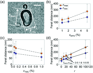
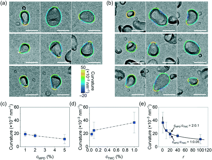
To study the relationship between the surface morphology of polyamide membranes and their synthesis conditions, we prepared a total of nine polyamide membrane samples following methods detailed above by varying the MPD (cMPD, 1–5%) and TMC (cTMC, 0.05–1%) concentrations, with the reaction time fixed at 60 s. Fig. 1b shows a photograph of a representative free-standing polyamide film floating on the water surface. The film was then gently scooped onto a TEM grid and dried in air for TEM imaging. As shown in Fig. 1c, the polyamide membranes clearly exhibit irregularly shaped and heterogeneous crumples, with differences in the crumple morphology depending on the MPD and TMC concentration(s). For example, an increase in the concentrations of either MPD or TMC leads to an increase in the number density of crumples (Fig. S3†). A higher cMPD increases the crumple size slightly, whereas a higher cTMC decreases the crumple size (Fig. 1c), suggesting competition between these two monomers likely due to their solubility anisotropy.31,44 The MPD molecules can diffuse deep into the hexane phase to grow large crumples, while TMC molecules with low solubility in the water phase react rapidly with MPD at the water–hexane interface into a self-limited polyamide film, consistent with previous work showing polyamide film growth is limited by MPD diffusion.6,31,45,46 To further understand the effect of monomer concentrations on crumple morphologies, we quantified a series of crumple structure parameters as detailed below.We first quantified the overall anisotropic shape of the crumples using local surface curvature and Feret distance following the method detailed above, both of which show opposite trends as the MPD and TMC concentrations change. Here the surface curvature of a pixel at the crumple contour is defined as the inverse of the radius of the best-fitted circle to the local arc containing the pixel. Fig. 2a and b shows zoomed-in TEM views of single crumples overlaid by their contour coloured to local surface curvature values. We applied this analysis to different polyamide membranes (at least 8 single crumples were counted for each membrane, Fig. S1 and S2†). As plotted in Fig. 2c, as cMPD increases from 1% to 5% at a fixed cTMC (0.05%), the average local surface curvature decreases from (19 ± 4) × 10−3 nm−1 to (14 ± 6) × 10−3 nm−1. The TMC concentration effect shows an opposite trend (Fig. 2d): the average local curvature increases from (14 ± 6) × 10−3 nm−1 to (37 ± 16) × 10−3 nm−1 as the cTMC increases from 0.05% to 1% at a fixed cMPD (1%). It may suggest that a higher cTMC at the hexane phase results in the earlier termination of crumple growth probably due to faster consumption of diffused MPD in the presence of a high concentration of TMC. Meanwhile, the Feret distances (Fmax, Fmin) of crumples measure how far the projected 2D view of the crumple shape deviates from a circle (Fig. 3a). As the cMPD increases from 1% to 5%, the average Feret distances monotonically increase, from 142 to 277 nm for Fmax and from 96 to 185 nm for Fmin (Fig. 3b) at a fixed cTMC (0.05%). In comparison, as we increase cTMC from 0.05% to 1%, the average Feret distances decrease, from 142 to 90 nm for Fmax and from 96 to 60 nm for Fmin (Fig. 3c) at a fixed cMPD (1%), suggesting the faster consumption of diffused MPD with higher cTMC in hexane. These results confirm again the two monomers have a competing effect on the crumple formation, which is suggested elsewhere.21,25,26,47
The competing dependence of the local surface curvature and Feret distances on cMPD and cTMC motivates us to plot these two parameters as a function of the concentration ratio of MPD to TMC (r = cMPD/cTMC). Both parameters fall onto consistent mathematical fitting forms. The average local surface curvature of the crumples logarithmically decays as r increases (R2 = 0.99, Fig. 2e). Interestingly, the two polyamide membrane samples synthesized at the same concentration ratio r of 20 but different monomer concentrations (1% MPD + 0.05% TMC vs. 2% MPD + 0.1% TMC) collapse nicely onto this fitting with similar curvatures ((1.9 ± 0.4) × 10−2 nm−1vs. (2.0 ± 0.6) × 10−2 nm−1, respectively as highlighted in Fig. 2e). The average Fmax and Fmin of crumples follow a linear increase as a function of r (R2 = 0.98, Fig. 3d), while the data from the two samples synthesized at the same r again matches with the fitting. These results indicate that the concentration ratio of MPD to TMC plays a role in the formation of crumple structures, charting a one-to-one relationship with the surface curvature and Feret distances of the crumples. Note that surface curvature and Feret distance directly relate to various parameters governing film transport properties, such as effective permeable area, surface-to-volume ratio, mass-per-area, local charge density, and local pKa of acidic ligands.13,18,48,49 For example, in one study, the crumpled morphology of a polyamide membranes provided higher permeance than that of a flat membrane by a factor of 4 owing to its higher effective permeable area.13 In our previous work, different crumple morphologies display distinct microenvironments as confirmed by ion adsorption tests using energy dispersive X-ray spectroscopy in a scanning transmission electron microscope.18
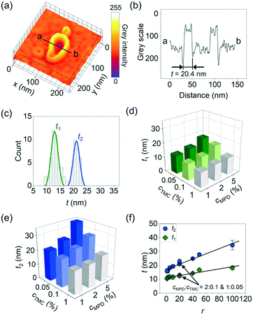
Beyond the above parameters that characterize the shape anisotropy of the crumples, we next measured the crumple thickness t that directly relates to solvent permeation length involved in molecular separation50,51 and mechanical stability required for the high operating pressures for reverse osmosis and nanofiltration.13,14,19,26 For this measurement, we plotted the grey scale intensity of a TEM image across a crumple (see the example in Fig. 4a and b, sample prepared with 1% MPD + 0.05% TMC). We repeated the measurement for 8 crumples synthesized at this condition, the distribution of which exhibits a clear bi-modal shape (t1 = 13 ± 1 nm; t2 = 21 ± 1 nm, Fig. 4c), consistent with our previous work when both dome and dimpled crumples were counted.18 Likewise, the polyamide membranes synthesized at other cMPD and cTMC show bi- or multi-modal distribution of the crumple thickness t (Fig. S4†). For ease of discussion, we plotted t1 and t2vs. the monomer concentrations, and both thicknesses increase as cMPD increases (Fig. 4d and e and S5†) and decrease as cTMC increases (Fig. 4d and e and S5†), again confirming the competing effects of MPD and TMC on crumple formation. Similarly, the average area and perimeter of crumples show the opposite trends as the MPD and TMC concentrations change whereas circularity remains constant (Fig. S6†).
When it comes to the dependence on the concentration ratio of MPD to TMC r, both t1 and t2 again fall into a unified mathematical form, scaling linearly to r (R2 = 0.98 for both, Fig. 4f). These results show that the monomer concentration ratio r serves as a potent handle for a one-to-one prediction of the membrane crumple thickness. The slope of the t2–r curve is larger than that of the t1–r curve, suggesting the formation of the thinner film is the rate-limiting step in the morphology development of the membrane. This observation is consistent with a crumpling mechanism identified in earlier studies where a uniform polymer sheet is formed first during interfacial polymerization and subsequently collapsed locally to form crumples.14,19,26,37
While the above quantitative and monotonic relationship linking these surface morphology parameters (e.g., surface curvature, Feret distances, thickness) to r can serve as a working curve to guide synthesis, we find that these parameters also follow universal scaling laws for the polyamide samples synthesized with varied monomer concentrations and seemingly disparate in structure (Fig. 5). We plotted collectively the data on Fmin, circularity, curvature, perimeter, and area of a total of 66 crumples (Fig. S1 and S2,† at least 8 crumples for each of the membranes synthesized) against Fmax (Fig. 5a–e). Here the x-axis of Fmax is arbitrarily chosen; the scaling works for any pairs of two morphology parameters. Note that the values of the morphology parameters vary by an order of magnitude or more across the 66 crumples of the 6 samples synthesized at different monomer concentrations: from 41 to 445 nm for Fmax, from 5 × 10⁻³ to 6.8 × 10⁻² nm−1 for local surface curvature, from 116 to 1327 nm for perimeter, and from 8.6 × 10² to 1.0 × 10⁵ nm2 for area (Fig. 5a–e). Out of this large parameter space we sampled, the morphology parameters consistently scale relative to each other. For instance, Fmin scales linearly to Fmax across all the polyamide membranes (R2 = 0.99, Fig. 5a) with the slope of 0.67 measuring the extent of elongation in the crumples (a perfect circular shape has a slope of 1). This constant extent of elongation is consistent with the circularity measurement, which presents average circularity of 0.78 with narrow standard deviation of 0.01 across the samples (Fig. 5b). The surface curvature of the crumple scales with a power law of exponent −1.03 to Fmax (R2 = 0.98, Fig. 5c), where an exponent of −1 is expected for a perfect circle. Similar fittings work for other morphology parameters such as perimeter and area of the crumple (Table S1†). The correlations of the various morphological parameters suggest that crumple growth follows unified morphology–synthesis relations.
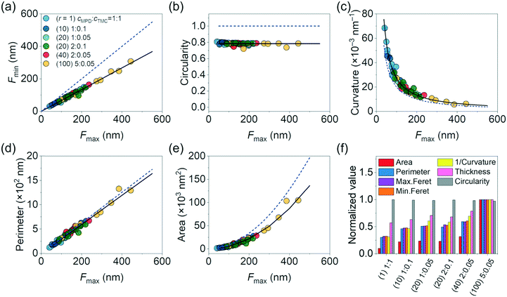 | ||
| Fig. 5 Plots of (a) minimum Feret distance, (b) circularity, (c) curvature, (d) perimeter, and (e) projected area of crumples as a function of maximum Feret distance. The dashed blue lines are the scaling of perfect circular shape: Fmin = Fmax (units of nm) in (a); circularity = 1 in (b); curvature (a unit of μm−1) = 2 × (Fmax)−1 in (c); perimeter (a unit of nm) = π × (Fmax) in (d); and area (a unit of nm2) = π × (Fmax/2)2 in (e). The black solid lines are fittings with a linear fit yielding a slope of 0.67 with R2 = 0.99 in (a); an average circularity of 0.78 in (b); a power law fit yielding curvature (a unit of μm−1) = 3.1 × (Fmax)–1.03 with R2 = 0.98 in (c); a linear fit yielding perimeter (a unit of nm) = 0.95π × (Fmax) with R2 = 0.98 in (d); and a power-law fit yielding area (a unit of nm2) = π × (Fmax/2.4)2 with R2 = 0.98 in (e), all confirming elongated structure of crumples. (f) Distribution of morphological characteristics normalized to the maximum value of each parameter across the samples. In the label of x-axis, polyamides with the ratio “j” of cMPD and cTMC, “k”% MPD, and “l”% TMC are expressed as “(j)k:l”. At least 8 crumples for each membrane were analysed (Fig. S1 and S2†). | ||
Lastly, we summarize all the morphological properties of different crumples in Fig. 5f. For convenient comparison in trends, we used inverse curvature. Morphological parameters are normalized to the maximum value of each one across the samples. All normalized parameters gradually increased with an increasing concentration ratio of MPD to TMC (r). The two polyamide films with the same concentration ratio r of 20 but different cMPD and cTMC (1% MPD + 0.05% TMC vs. 2% MPD + 0.1% TMC) had highly similar values across all crumple morphology parameters (Fig. 5f), similar to those observed elsewhere.32 The results are in agreement with our predictions of MPD–TMC competition and support the idea that reactant ratios dictate crumple structure. It is noted that our previous study investigated crumple structure in 3D.18 Thus, further studies on 3D morphological parameters such as crumple height are needed to fully understand crumpling mechanisms and structure–synthesis correlation of polyamide membranes.
Conclusions
In summary, using our morphometry platform we demonstrated that crumpled polyamide films follow quantitative synthesis–morphology relationships. We compared a series of polyamide films with varied amine and acyl chloride monomer concentrations with fixed reaction time of 60 s. Our results are consistent with an hypothesis that the crumple growth process is the result of competition between the amine monomer in the water phase and the acyl chloride monomer in the organic phase (MPD vs. TMC). The concentrations of the two monomers tune crumple morphological parameters such as surface curvature, Feret distance, thickness, perimeter, and area monotonically but in the reverse directions. Such a competition process between two monomers was further supported by scaling morphological parameters as a function of the concentration ratio of MPD to TMC (r = cMPD/cTMC). Furthermore, we found a unified mechanistic principle of crumple formation where the individual crumples, although seemingly unrelated in shape, can be scaled as a function of morphological properties. We anticipate that this morphometry platform can be applicable to other nanoscale soft materials and provides engineering strategies based directly on synthesis–morphology–function relationships.Conflicts of interest
There are no conflicts to declare.Acknowledgements
The authors would like to acknowledge funding and technical support by the Air Force Office of Scientific Research Young Investigator Program (AFOSR-YIP) project FA9550-17-1-0296 and the Defense University Research Instrumentation Program (under AFOSR Project FA9550-18-1-0393). TEM imaging was carried out, in part, in the Materials Research Laboratory (MRL) Central Research Facilities, University of Illinois.References
- M. R. Chowdhury, J. Steffes, B. D. Huey and J. R. McCutcheon, Science, 2018, 361, 682–686 CrossRef CAS PubMed.
- M. Elimelech and W. A. Phillip, Science, 2011, 333, 712–717 CrossRef CAS PubMed.
- R. Larson, J. Cadotte and R. Petersen, Desalination, 1981, 38, 473–483 CrossRef CAS.
- V. Freger, Langmuir, 2005, 21, 1884–1894 CrossRef CAS.
- Y. Zhang, N. E. Benes and R. G. Lammertink, Lab Chip, 2015, 15, 575–580 RSC.
- G.-Y. Chai and W. B. Krantz, J. Membr. Sci., 1994, 93, 175–192 CrossRef CAS.
- J. Wang, R. Xu, F. Yang, J. Kang, Y. Cao and M. Xiang, J. Membr. Sci., 2018, 556, 374–383 CrossRef CAS.
- Y. Suzuki, Y. Koyano and M. Nagaoka, J. Phys. Chem. B, 2015, 119, 6776–6785 CrossRef CAS PubMed.
- J. Muscatello, E. Müller, A. Mostofi and A. Sutton, J. Membr. Sci., 2017, 527, 180–190 CrossRef CAS.
- T. D. Matthews, H. Yan, D. G. Cahill, O. Coronell and B. J. Mariñas, J. Membr. Sci., 2013, 429, 71–80 CrossRef CAS.
- B. Ukrainsky and G. Z. Ramon, J. Membr. Sci., 2018, 566, 329–335 CrossRef CAS.
- X.-H. Ma, Z.-K. Yao, Z. Yang, H. Guo, Z.-L. Xu, C. Y. Tang and M. Elimelech, Environ. Sci. Technol. Lett., 2018, 5, 123–130 CrossRef CAS.
- S. Karan, Z. Jiang and A. G. Livingston, Science, 2015, 348, 1347–1351 CrossRef CAS.
- H. Yan, X. Miao, J. Xu, G. Pan, Y. Zhang, Y. Shi, M. Guo and Y. Liu, J. Membr. Sci., 2015, 475, 504–510 CrossRef CAS.
- F. A. Pacheco, I. Pinnau, M. Reinhard and J. O. Leckie, J. Membr. Sci., 2010, 358, 51–59 CrossRef CAS.
- C. Y. Tang, Y.-N. Kwon and J. O. Leckie, J. Membr. Sci., 2007, 287, 146–156 CrossRef CAS.
- A. K. Ghosh, B.-H. Jeong, X. Huang and E. M. Hoek, J. Membr. Sci., 2008, 311, 34–45 CrossRef CAS.
- X. Song, J. W. Smith, J. Kim, N. J. Zaluzec, W. Chen, H. An, J. M. Dennison, D. G. Cahill, M. A. Kulzick and Q. Chen, ACS Appl. Mater. Interfaces, 2019, 11, 8517–8526 CrossRef CAS PubMed.
- M. Hirose, H. Ito and Y. Kamiyama, J. Membr. Sci., 1996, 121, 209–215 CrossRef CAS.
- X. Ma, Z. Yang, Z. Yao, H. Guo, Z. Xu and C. Y. Tang, J. Colloid Interface Sci., 2019, 540, 382–388 CrossRef CAS.
- B. Khorshidi, T. Thundat, B. A. Fleck and M. Sadrzadeh, Sci. Rep., 2016, 6, 22069 CrossRef.
- X. Li, Q. Li, W. Fang, R. Wang and W. B. Krantz, J. Membr. Sci., 2019, 580, 12–23 CrossRef CAS.
- J. E. Gu, S. Lee, C. M. Stafford, J. S. Lee, W. Choi, B. Y. Kim, K. Y. Baek, E. P. Chan, J. Y. Chung and J. Bang, Adv. Mater., 2013, 25, 4778–4782 CrossRef CAS PubMed.
- S. Gao, Y. Zhu, Y. Gong, Z. Wang, W. Fang and J. Jin, ACS Nano, 2019, 13(5), 5278–5290 CrossRef CAS PubMed.
- B. Khorshidi, T. Thundat, B. Fleck and M. Sadrzadeh, RSC Adv., 2015, 5, 54985–54997 RSC.
- J. Xu, H. Yan, Y. Zhang, G. Pan and Y. Liu, J. Membr. Sci., 2017, 541, 174–188 CrossRef CAS.
- O. Coronell, B. J. Mariñas, X. Zhang and D. G. Cahill, Environ. Sci. Technol., 2008, 42, 5260–5266 CrossRef CAS PubMed.
- O. Coronell, M. I. González, B. J. Mariñas and D. G. Cahill, Environ. Sci. Technol., 2010, 44, 6808–6814 CrossRef CAS.
- O. Coronell and D. G. Cahill, Environ. Sci. Technol., 2009, 43, 5042–5048 CrossRef CAS.
- O. Coronell, B. J. Marinas and D. G. Cahill, Environ. Sci. Technol., 2011, 45, 4513–4520 CrossRef CAS.
- A. Nowbahar, V. Mansard, J. M. Mecca, M. Paul, T. Arrowood and T. M. Squires, J. Am. Chem. Soc., 2018, 140, 3173–3176 CrossRef CAS.
- J. M. Dennison, X. Xie, C. J. Murphy and D. G. Cahill, ACS Appl. Nano Mater., 2018, 1, 5008–5018 CrossRef CAS.
- X. Song, S. Qi, C. Y. Tang and C. Gao, J. Membr. Sci., 2017, 540, 10–18 CrossRef CAS.
- L. A. Perry and O. Coronell, J. Membr. Sci., 2013, 429, 23–33 CrossRef CAS.
- D. L. Shaffer, M. E. Tousley and M. Elimelech, J. Membr. Sci., 2017, 525, 249–256 CrossRef CAS.
- D. Ren, J. I. N. Yeo, T.-Y. Liu and X. Wang, Polym. Chem., 2019, 10, 2769–2773 RSC.
- L. Lin, R. Lopez, G. Z. Ramon and O. Coronell, J. Membr. Sci., 2016, 497, 365–376 CrossRef CAS.
- F. Pacheco, R. Sougrat, M. Reinhard, J. O. Leckie and I. Pinnau, J. Membr. Sci., 2016, 501, 33–44 CrossRef CAS.
- T. E. Culp, Y.-X. Shen, M. Geitner, M. Paul, A. Roy, M. J. Behr, S. Rosenberg, J. Gu, M. Kumar and E. D. Gomez, Proc. Natl. Acad. Sci. U. S. A., 2018, 115, 8694–8699 CrossRef CAS.
- M. M. Kłosowski, C. M. McGilvery, Y. Li, P. Abellan, Q. Ramasse, J. T. Cabral, A. G. Livingston and A. E. Porter, J. Membr. Sci., 2016, 520, 465–476 CrossRef.
- J. Schindelin, I. Arganda-Carreras, E. Frise, V. Kaynig, M. Longair, T. Pietzsch, S. Preibisch, C. Rueden, S. Saalfeld and B. Schmid, Nat. Methods, 2012, 9, 676 CrossRef CAS.
- J. Kim, X. Song, A. Kim, B. Luo, J. W. Smith, Z. Ou, Z. Wu and Q. Chen, Macromol. Rapid Commun., 2018, 39, 1800101 CrossRef.
- Z. Ou, X. Song, W. Huang, X. Jiang, S. Qu, Q. Wang, P. V. Braun, J. S. Moore, X. Li and Q. Chen, ACS Appl. Mater. Interfaces, 2018, 10, 40990–40995 CrossRef CAS.
- P. W. Morgan and S. L. Kwolek, J. Polym. Sci., 1959, 40, 299–327 CrossRef CAS.
- Y. Jin and Z. Su, J. Membr. Sci., 2009, 330, 175–179 CrossRef CAS.
- J. Ji and M. Mehta, J. Membr. Sci., 2001, 192, 41–54 CrossRef CAS.
- M. Rastgar, A. Shakeri and H. Salehi, Environ. Sci. Pollut. Res., 2019, 26, 1181–1191 CrossRef CAS.
- D. A. Walker, E. K. Leitsch, R. J. Nap, I. Szleifer and B. A. Grzybowski, Nat. Nanotechnol., 2013, 8, 676 CrossRef CAS PubMed.
- Z. Tan, S. Chen, X. Peng, L. Zhang and C. Gao, Science, 2018, 360, 518–521 CrossRef CAS.
- J. G. Wijmans and R. W. Baker, J. Membr. Sci., 1995, 107, 1–21 CrossRef CAS.
- G. M. Geise, H. B. Park, A. C. Sagle, B. D. Freeman and J. E. McGrath, J. Membr. Sci., 2011, 369, 130–138 CrossRef CAS.
Footnote |
| † Electronic supplementary information (ESI) available: TEM images of polyamide membranes; characterization of thickness and number density of polyamide crumples; morphological parameter fittings. See DOI: 10.1039/c9me00132h |
| This journal is © The Royal Society of Chemistry 2020 |


![[thin space (1/6-em)]](https://www.rsc.org/images/entities/char_2009.gif) ln(
ln(