
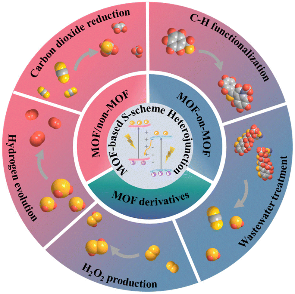
Metal–organic framework-based S-scheme heterojunction photocatalysts
Ling
Yuan
b,
Peiyang
Du
b,
Luli
Yin
a,
Jiamin
Yao
a,
Jing
Wang
*a and
Chao
Liu
 *b
*b
aSchool of Chemical and Environmental Engineering, Shanghai Institute of Technology, Shanghai 201418, P.R. China. E-mail: jingwang@sit.edu.cn
bSchool of Chemistry and Molecular Engineering, East China Normal University, Shanghai 200241, P.R. China. E-mail: cliu@chem.ecnu.edu.cn
First published on 7th February 2024
Abstract
Photocatalysis is a promising technology to resolve energy and environmental issues, where the design of high-efficiency photocatalysts is the central task. As an emerging family of photocatalysts, semiconducting metal–organic frameworks (MOFs) with remarkable features have demonstrated great potential in various photocatalytic fields. Compared to MOF-based photocatalysts with a single component, construction of S-scheme heterojunctions can render MOFs with enhanced charge separation, redox capacity and solar energy utilization, and thus improved photocatalytic performance. Herein, an overview of the recent advances in the design of MOF-based S-scheme heterojunctions for photocatalytic applications is provided. The basic principle of S-scheme heterojunctions is introduced. Then, three types of MOF-based S-scheme heterojunctions with different compositions are systematically summarized including MOF/non-MOF, MOF-on-MOF and MOF-derived heterojunctions. Afterwards, the enhanced performances of MOF-based S-scheme heterojunctions in hydrogen production, CO2 reduction, C–H functionalization, H2O2 production and wastewater treatment are highlighted. Lastly, the current challenges and future prospects regarding the design and applications of MOF-based S-scheme heterojunctions are discussed to inspire the further development of this emerging field.
 Ling Yuan | Ling Yuan is currently a Ph.D. student under the supervision of Prof. Chao Liu and Prof. Chengzhong Yu at East China Normal University. Her research field is MOF-based nanomaterials for applications in photocatalysis. |
 Jing Wang | Jing Wang received her Ph.D. degree (2018) from Nanjing University of Science and Technology. She worked as a postdoctoral fellow in Prof. Chengzhong Yu's group at East China Normal University (2018–2022). She is currently an associate professor at the Shanghai Institute of Technology. Her research focuses on the design of functional nanomaterials for environmental remediation and electrocatalysis. |
 Chao Liu | Chao Liu received his bachelor's (2012) and Ph.D. degrees (2018) from Nanjing University of Science and Technology. He worked as a postdoctoral fellow in Prof. Chengzhong Yu's group at East China Normal University (2018–2021). He is currently a professor at East China Normal University. His research focuses on the design and synthesis of nanostructured MOF materials for catalysis. |
1. Introduction
The energy crisis and environmental pollution have become two worldwide challenges faced by human society. To resolve these problems, photocatalysis technology offers a promising strategy.1,2 Using the powerful and inexhaustible solar energy as an energy input, photocatalysis can not only produce valuable chemicals, but also remediate environmental damage by degrading pollutants.3,4 Currently, the greatest bottleneck of photocatalysis is the low photocatalytic efficiency caused by rapid electron–hole recombination and poor light harvesting ability.5Over the past few decades, major efforts have been devoted to the exploration of high-efficiency photocatalysts. Plenty of semiconducting materials including metal oxides,6,7 metal sulfides,8,9 metal phosphides,10,11 metal oxyhalides,12,13 C3N414,15 covalent organic frameworks (COFs),16,17 and metal–organic frameworks (MOFs)18,19 have been reported as photocatalysts for various photocatalytic reactions. Among them, MOFs, known as a type of porous crystalline material, have received specific attention.20,21 Owing to their excellent physicochemical properties such as a large specific surface area, high porosity, dispersed metal sites and a ligand–metal charge transfer pathway,4,22 semiconducting MOFs have demonstrated great potential in pollutant degradation,23 water splitting,24 organic transformation,25 CO2 reduction26 and N2 fixation.27 Through precise regulation of the structures (e.g. pore space) and/or compositions (e.g. metal and/or ligand types) of MOFs, high activity and selectivity can be achieved in specific reactions.18,19,28 Even so, for pristine MOFs with single compositions, the easy recombination of photocarriers restricts their photocatalytic performances.29,30
To improve their photocatalytic activity, several modification strategies including introducing defects,28,31 doping heterometals/ligands,32,33 loading co-catalysts and constructing heterojunctions have been developed.34,35 Compared to other strategies, heterojunction construction by integrating two semiconductors with different band structures exhibits unique advantages in promoting charge separation.36–38 To date, numerous organic or inorganic semiconductors such as COFs,37 hydrogen-bonded organic frameworks (HOFs),38 metal sulfides,39 metal oxides40 and metal hydroxides41 have been adopted for coupling with MOFs, resulting in MOF-based heterojunctions with different working mechanisms. Among them, the step-scheme (S-scheme) charge transfer mechanism stands out because it can significantly facilitate photogenerated electron–hole separation and maximally preserve the redox ability of semiconducting units. Inspiringly, the design and application of MOF-based S-scheme heterojunction photocatalysts has thus become a rapidly expanding field. Synthetic strategies including hydro/solvothermal treatment, the impregnation method and high-temperature pyrolysis have been developed for the fabrication of MOF-based S-scheme heterojunctions with controllable components.40,42,43 Their applications have also been investigated from efficient hydrogen evolution, CO2 reduction, organic synthesis, H2O2 production to pollutant degradation with enhanced activity compared to single MOFs.42,44–46 For S-scheme heterojunctions, several excellent reviews have been contributed,47–49 while a dedicated review of emerging MOF-based S-scheme heterojunctions is still lacking but highly desired. In this context, a timely summary on the recent advances of MOF-based S-scheme heterojunctions with regard to their synthesis, structures and applications is provided in this review (Scheme 1).
 | ||
| Scheme 1 An overview of the structures and applications of MOF-based S-scheme heterojunction photocatalysts. | ||
Firstly, a brief introduction of different types of heterojunctions is presented with a focus on their working mechanisms. Secondly, the obtained MOF-based S-scheme heterojunctions with different compositions are systematically outlined. Thirdly, the enhanced performances of the heterojunctions in various photocatalytic reactions are highlighted. Finally, the current challenges and future perspectives are discussed for promoting the further development of this fascinating field.
2. Different types of heterojunctions and their charge transfer mechanisms
Construction of heterojunction photocatalysts by conjugating two dissimilar semiconductors (semiconductors 1 and 2, denoted as S1 and S2) has been widely recognized as an important strategy to improve their photocatalytic activity by facilitating the separation and utilization of photogenerated electron–hole pairs.5 The currently existing heterojunctions can be mainly divided into six types: type I with a straddling gap, type II with a staggered gap, type III with a broken gap, traditional Z-scheme, all-solid-state Z-scheme and S-scheme heterojunctions.50 Their energy level structures are schematically presented. For type-I heterojunctions (Fig. 1a), the conduction band (CB) and the valence band (VB) of semiconductor S2 straddle between the VB and the CB of semiconductor S1. The photogenerated electrons and holes are both accumulated on S2 with a small band gap, resulting in high recombination probability and weak redox ability.51 For type-II heterojunctions (Fig. 1b), both the CB and VB positions of S1 are more negative than S2, forming a staggered alignment. As a result, the photogenerated electrons migrate from S1 to S2 with an adverse transfer direction of photogenerated holes, enabling a spatial separation of photogenerated electron–hole pairs. Nevertheless, there also exist several disadvantages that prevent the wide application of type-II heterojunctions. Because the CB level of S2 is more positive than that of S1 and the VB level of S1 is more negative than that of S2, the redox capability of both electrons and holes is reduced. In addition, the electrostatic repulsion from electrons in S2 and holes in S1 dramatically hinders the continuous electron/hole migration.52 The band structure of type-III heterojunctions is similar to that of type-II heterojunctions except that the VB of S1 is higher than the CB of S2 without overlap between two semiconductors. In this case, the electron and hole transfer between S1 and S1 cannot take place (Fig. 1c).53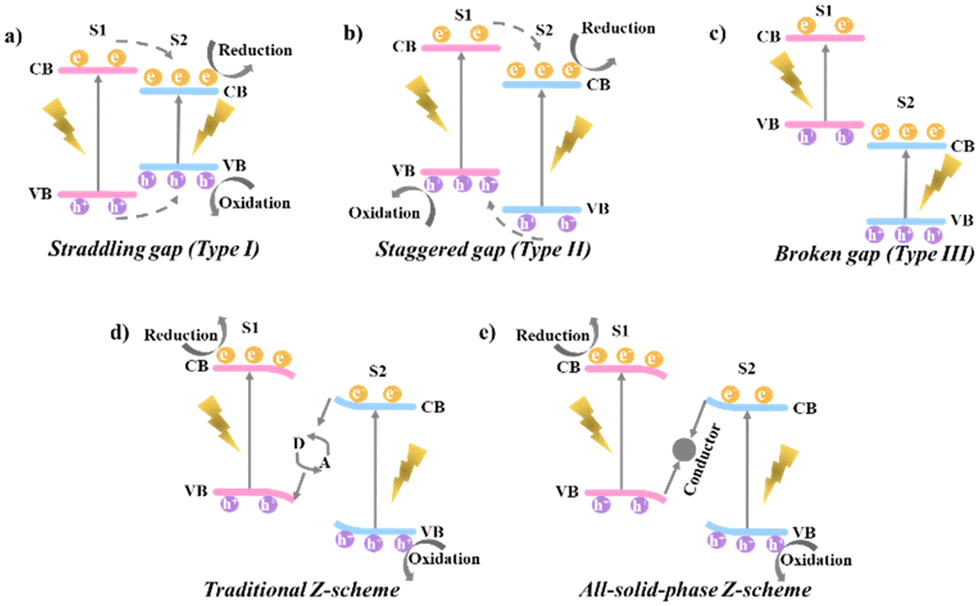 | ||
| Fig. 1 Band structures and charge transfer directions in (a) straddling gap (type I), (b) staggered gap (type II), (c) broken gap (type III), (d) traditional Z-scheme, and (e) all-solid-state Z-scheme heterojunctions. | ||
To address the problems faced by the above three types of heterojunctions, researchers developed a type of traditional Z-scheme heterojunction with ionic acceptor/donor (A/D) couples (e.g. Fe3+/Fe2+, I3−/I−) inspired by the natural photosynthesis in plants (Fig. 1d).54–56 During photocatalytic reactions, the photogenerated electrons on the CB of S2 transfer to the VB of S1 via the redox reactions between A/D pairs.57 Typically, the electrons on the CB of S2 reduce A into D, and the D is subsequently oxidized into A by the holes on the VB of S1. On this basis, the electrons and holes are respectively accumulated on the CB of S1 and the VB of S2, giving higher reduction and oxidation potentials and spatial charge separation.54,58 However, the application of such a system is limited in the solution phase and pH-sensitive redox ion pairs are inevitably needed with the undesired light shielding effect.47 To broaden the application scope of the Z-scheme mechanism, all-solid-state Z-scheme heterojunctions are proposed, where the A/D pairs are replaced by a conductor as the electron mediator (Fig. 1e).59 The integration of a conductor at the interface of S1 and S2 forms an ohmic contact with low electron transport resistance. The photogenerated electrons on the CB of S2 can directly migrate to the VB of S1 for consuming the holes, accomplishing the Z-scheme charge transfer pathway in an all-solid state with extended applications in solution, gas and solid media.54,60,61 Even though promising, the electron mediates are generally noble metals with high cost, restricting the practical applications of these photocatalytic materials.54
In this context, an innovative heterojunction concept, named step-scheme (S-scheme) heterojunctions (the sixth type), was proposed by Yu's group in 2019 and 2020.3,47,48 In an S-scheme heterojunction photocatalyst, a reduction photocatalyst (RP) and an oxidation photocatalyst (OP) with a staggered band structure are directly combined. The RP exhibits higher CB, VB and Fermi levels than the OP.47 The charge transfer route within an S-scheme heterojunction is presented in Fig. 2. When in contact, the free electrons in RP diffuse spontaneously into OP due to the different Fermi levels. Until alignment, a built-in electric field pointing from RP to OP is created with upward and downward band bending of RP and OP, respectively. Under light irradiation, the photogenerated carriers were excited from the VB to the CB in both RP and OP, generating photoelectrons and holes. Driven by the band bending and interface electric field, the electrons in the CB of OP will recombine with the holes in the VB of RP, leaving powerful electrons in the CB of RP and holes in the VB of OP for participating in the reduction and oxidation reactions, respectively. Reasonably, the S-scheme heterojunction can not only effectively promote the spatial carrier separation, but also maximize the photocatalytic redox capacity to greatly improve the photocatalytic activity.48
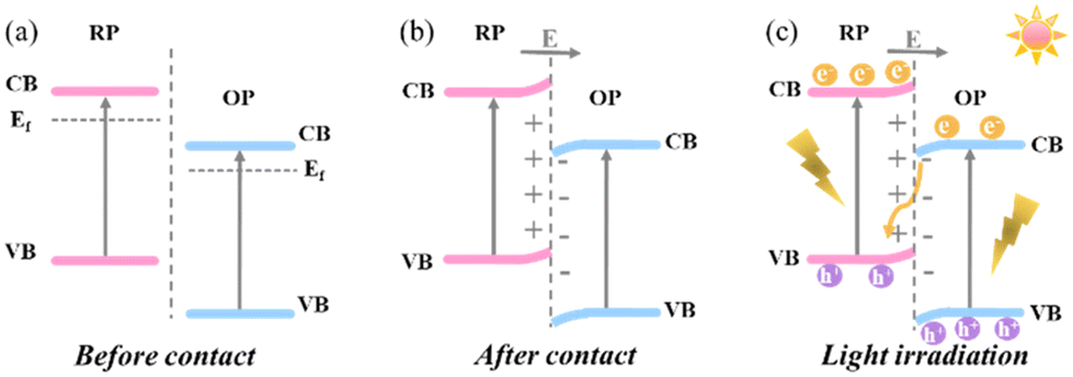 | ||
| Fig. 2 Graphical illustration of the charge migration process of S-scheme heterojunctions. (a) before contact; (b) after contact; and (c) photogenerated charge carrier transfer under light irradiation. | ||
3. Methods for identifying the S-scheme charge transfer mechanism
To probe the proposed charge transfer pathway in S-scheme heterojunctions, advanced techniques including in situ irradiated X-ray photoelectron spectroscopy (ISIXPS), Kelvin probe force microscopy (KPFM), electron paramagnetic resonance (EPR) spectroscopy and density functional theory (DFT) calculations can provide direct evidence. The working principles of these methods will be discussed in the following sections with the combination of typical examples.3.1 ISIXPS
XPS is an analytical technique that can sensitively detect the changes in the elemental binding energy and chemical environment, also referred to as the chemical shift.62–64 The chemical shift caused by the variation in the valence state and electron density can be facilely determined by the binding energy shift in XPS spectra. Generally, the binding energy decreases by obtaining electrons, while increases by losing electrons.47 On this basis, the electron transfer within the S-scheme heterojunctions is able to be measured by comparing the binding energies of RP and OP with and without light illumination. Once the contact is formed in the dark, the electron transfer from RP to OP will increase the binding energy of RP and decrease the binding energy of OP. Under irradiation, an opposite change will be observed by S-scheme charge transfer. Given that the S-scheme and type-II heterojunctions have completely different carrier migration pathways, ISIXPS characterization has been extensively adopted for differentiating these two types of heterojunctions.65 For example, Xu et al. reported an SnO2/Cs3Bi2Br9 (SC4) S-scheme heterojunction via the electrostatic self-assembly of SnO2 nanofibers and lead-free Cs3Bi2Br9 quantum dots (QDs).66In situ XPS under light and dark conditions was performed to determine the charge transfer mechanism (Fig. 3). In the absence of light, the binding energies of Sn 3d and O 1s in the heterojunction negatively shifted (Fig. 3a and b), whereas the binding energies of Bi 4f and Br 3d positively shifted (Fig. 3c and d) compared with those of single SnO2 and Cs3Bi2Br9, suggesting the electron migration from Cs3Bi2Br9 to SnO2. In the presence of light, the binding energies of the corresponding elements oppositely shifted with a reversed electron transfer direction, in agreement with the S-scheme mechanism.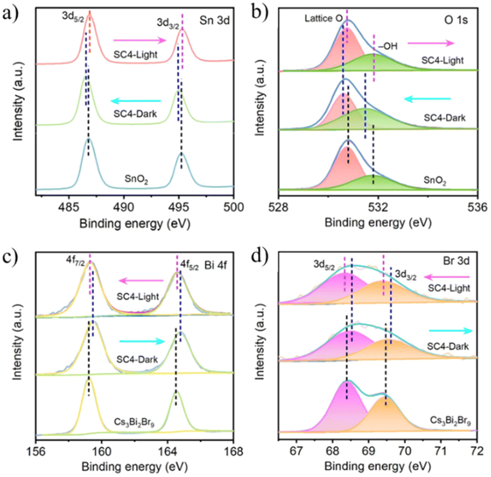 | ||
| Fig. 3 High-resolution XPS spectra of (a) Sn 3d, (b) O 1s, (c) Bi 4f, and (d) Br 3d for SnO2, Cs3Bi2Br9, and SC4 obtained in the dark and under UV light irradiation, respectively. Reprinted with permission from ref. 66. Copyright 2023 American Chemical Society. | ||
3.2 KPFM
As a derivative of atomic force microscopy (AFM), KPFM can not only scan the surface morphology, but also monitor the surface potential.44,67 For an S-scheme heterojunction, the photogenerated electrons and holes are accumulated on RP and OP under light irradiation, reflected by the increased and decreased surface potentials of OP and RP in KPFM, respectively.68 As a typical example using KPFM to verify the S-scheme mechanism, Qiao et al. prepared a TiO2/FePS3 (TF) S-scheme heterojunction photocatalyst by coupling TiO2 and 2D FePS3 (FPS) nanosheets.69 The AFM and KPFM results showed that there existed a surface potential difference between TiO2 and FPS before exposure to light, corresponding to the formation of a built-in electric field pointing from FPS to TiO2. After illumination, the surface potential of FPS and TiO2 became lower and higher, respectively, following the charge transfer mechanism of S-scheme heterojunctions (Fig. 4a–d).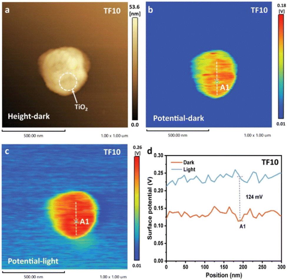 | ||
| Fig. 4 (a) AFM and (b) KPFM images of TF in the absence of light. (c) KPFM image of TF under UV light illumination at 365 nm. (d) Corresponding surface potential profiles. Reprinted with permission from ref. 69. Copyright 2022 Wiley-VCH. | ||
3.3 DFT calculations
Apart from experimental investigations, the electronic structures of heterojunctions can be simulated by DFT calculations, providing theoretical clues to help elucidate the charge migration mechanism.70–72 The crucial optical parameters including work function and density of states can be explored by DFT calculations. Moreover, the charge density difference (ΔP) between OP and RP can be directly utilized to disclose the interfacial electron transfer, where a positive and negative ΔP represents the electron accumulation and depletion, respectively. In other words, the interfacial electron transfer from RP to OP upon their contact in the dark gives a negative ΔP in RP and a positive ΔP in OP.73,74 For instance, Zhang et al. investigated the enhanced catalytic performance over a Cu2V2O7 (CVO)/α-Fe2O3 S-scheme heterojunction by DFT calculations.75 The work functions of CVO (Fig. 5a) and Fe2O3 (Fig. 5b) were computed to be 5.09 and 6.87 eV, respectively. When the two components are in contact, Fe2O3 attracted the electrons from CVO until the Fermi energy level was equilibrated, creating a built-in electric field pointing from CVO with a negative ΔP to Fe2O3 with a positive ΔP (Fig. 5c). In addition, the charge density difference at the heterojunction interface between CVO and Fe2O3 was simulated to determine the charge transfer. The results in Fig. 5d show the electron transfer from CVO to Fe2O3. Thus, the CVO and Fe2O3 sides exhibit positive and negative charges, respectively, creating a built-in electric field at the interface (Fig. 5e).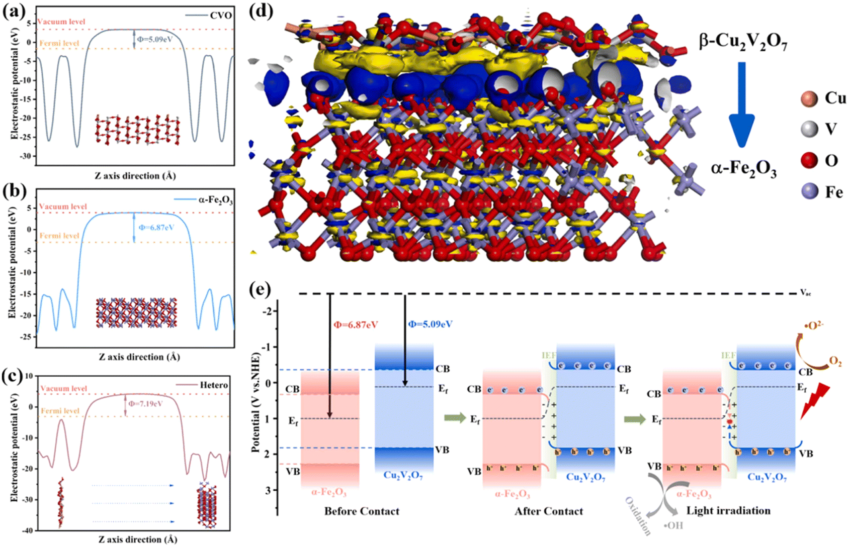 | ||
| Fig. 5 Work functions of (a) CVO (010), (b) α-Fe2O3 (001), and (c) heterojunctions. (d) Charge density difference at the CVO (010)/α-Fe2O3 (001) interface, yellow indicates the loss of electrons and blue represents the gain of electrons. (e) Photocatalytic mechanism of S-scheme heterojunctions. Reprinted with permission from ref. 75. Copyright 2023 Elsevier. | ||
3.4 EPR
Different from the above techniques that can provide direct evidence of charge transfer, EPR offers an indirect method for understanding the mechanism of S-scheme heterojunctions from the perspective of redox capability. Specifically, the radicals formed during the photocatalytic reaction, such as superoxide radicals (˙O2−) requiring a strong reduction capability and hydroxyl radicals (˙OH) requiring a strong oxidation capability, are detected by EPR. With the maximized redox power of S-scheme heterojunctions, higher EPR signals of ˙OH and ˙O2− radicals than OP and RP can be usually detected.76–78 Following this principle, Wang et al. applied EPR to unveil the photocatalytic mechanism of the carbon quantum dot/Bi2WO6 (CQD/Bi2WO6) S-scheme heterojunction.79 As displayed in Fig. 6a, b, d and e, only the EPR signal of ˙O2− can be detected for CQDs as the RP under visible light, while for Bi2WO6 as the OP, the signal of ˙O2− is invisible with identifiable ˙OH signals. In contrast, through the combination of CQDs with Bi2WO6, the stronger signals of both ˙O2− and ˙OH are ascribed to the formation of an S-scheme heterojunction.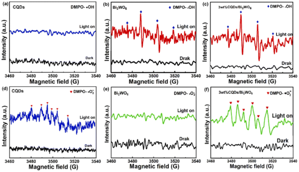 | ||
| Fig. 6 EPR signals of CQDs, Bi2WO6, and 3 wt% CQDs/Bi2WO6 for DMPO-OH (a, b and c) and DMPO-O2− (d, e, and f). Reprinted with permission from ref. 79. Copyright 2023 Elsevier. | ||
4. Synthesis and structures of MOF-based S-scheme photocatalysts
Given that MOF-based S-scheme photocatalysts can simultaneously integrate the merits of both semiconducting MOFs and S-scheme heterojunctions, significant efforts have been devoted to their synthesis. The resulting S-scheme heterojunctions can be approximately classified into the following types from the aspect of their components: MOF/non-MOF, MOF-on-MOF and MOF-derived S-scheme heterojunctions.4.1 MOF/non-MOF heterojunctions
The abundant surface chemistry of MOFs endows them with great potential for hybridization with other functional materials toward S-scheme heterojunctions.35 Various non-MOF semiconductors such as metal oxides,40,45,80 metal sulfides,81–84 metal phosphides,85,86 and carbon-based composites45,64,87 have been involved in synthetic routes including solvothermal treatment and the impregnation method. For example, Tang et al. reported a novel CoFe2O4/iron-based MOF (MIL-101, (MIL = Material Institute Lavoisier)) S-scheme heterojunction photocatalyst by a simple solvothermal method with CoFe2O4 nanoparticles distributed on the surface of MIL-101(Fe) octahedra (Fig. 7a).40 In their synthesis, the pre-formed CoFe2O4 nanoparticles were in situ adhered onto the surface of MIL-101(Fe) octahedra by reacting with terephthalic acid (H2BDC) and FeCl3 6H2O in N,N-dimethylformamide (DMF) solution at 110 °C for 20 h. Using a similar procedure, an S-scheme heterojunction of zeolitic imidazolate framework-8 (ZIF-8)@Zn0.5Cd0.5S with sulfur vacancies (T-ZCSv) was also prepared (Fig. 7b).84 Firstly, T-ZCSv was synthesized by the hydrothermal reaction of Zn(CH3CO2)2·2H2O, Cd(CH3CO2)2·2H2O and CH3CSNH2 in 4 M NaOH at 180 °C for 24 h. The obtained T-ZCSv was then added to the reaction solution containing 1-methylimidazole (1-MeIM), 2-methylimidazole (2-MeIM) and Zn(NO3)2·6H2O for aging in methanol solution at room temperature for 24 h. The resulting T-ZCSv exhibited a dodecahedral morphology with clear lattice fringes of Zn0.5Cd0.5S nanocrystals in different regions, consistent with the corresponding fast Fourier transform (FFT) patterns (Fig. 7c–e).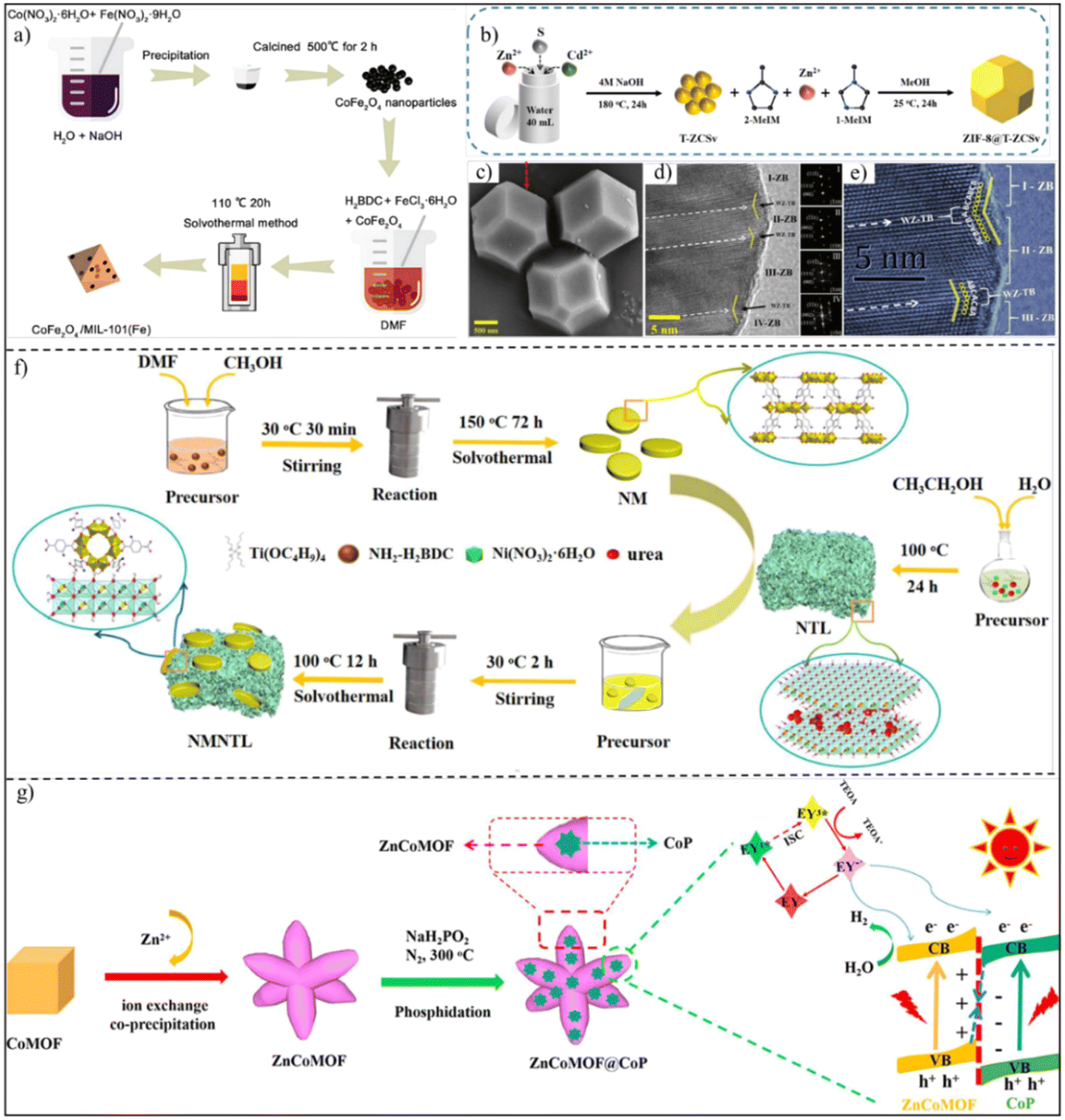 | ||
| Fig. 7 (a) Scheme of the synthetic process of the CuFe2O4/MIL-101(Fe) heterojunction. Reprinted with permission from ref. 40. Copyright 2022 Elsevier. (b) Scheme showing the formation process. (c) SEM, (d) TEM and (e) HRTEM images of the ZIF-8@T-ZCSv heterojunction. Reprinted with permission from ref. 84. Copyright 2023 the Royal Society of Chemistry. (f) Diagram of the preparation route of NM, NTL and NMNTL. Reprinted with permission from ref. 41. Copyright 2023 the Royal Society of Chemistry. (g) Flow chart of the preparation of the ZnCoMOF@CoP S-scheme heterojunction. Reprinted with permission from ref. 86. Copyright 2022 American Chemical Society. | ||
As well as metal oxides and metal sulfides, layered double hydroxides (LDHs) can also be merged with MOFs toward S-scheme heterojunctions.41,42 As a typical example reported by Zhong and co-authors, a Ti-based NH2-MIL-125 (NM) nanocake was synthesized via a one-pot solvothermal route as the substrate, followed by the growth of NiTi-LDH (NTL) nanosheets by a urea homogeneous precipitation method (Fig. 7f), forming MOF/LDH heterojunctions (NMNTL).41 Different from the above studies, by adding non-MOF semiconductors during MOF growth or using MOFs as starting materials for the growth of non-MOF semiconductors, S-scheme heterojunctions with controllable compositions can also be obtained by partial pyrolysis of MOFs. For instance, through heat treatment of ZnCo-MOF at 300 °C under a PH3 reducing atmosphere, Jin et al. constructed a ZnCo-MOF@CoP S-scheme heterojunction with the in situ generation of CoP nanocrystals on the surface of the preserved ZnCo-MOF (Fig. 7g).86
Carbon nitride (g-C3N4) is a fascinating metal-free conjugated polymer and one of the most widely studied semiconductors in various fields.88–91 Recently, S-scheme heterojunctions prepared by the hybridization of g-C3N4 with MOFs have also been reported.43,62 Vahid Safarifard's group reported the interfacial growth of four different cerium-based MOFs onto the surface of g-C3N4via solvothermal treatment (Fig. 8a).43 In the powder X-ray diffraction (XRD) pattern, the major diffraction peaks of both g-C3N4 and Ce-based MOFs (Ce-BDC, as a typical example) could be detected (Fig. 8b). Moreover, the N2 adsorption–desorption isotherms of g-C3N4/Ce-BDC (Fig. 8c) exhibited type-III curves with an H3-type hysteresis loop, similar to those of Ce-BDC. Compared with C3N4, graphdiyne possesses a higher specific surface area and higher electrical conductivity, making it a promising candidate as a photocatalyst.92–95 In this regard, Jin and coworkers decorated 2D graphdiyne (GDY) nanosheets onto 3D ZnCo-ZIF via impregnation treatment in water at 80 °C for 2 h, giving rise to a 2D/3D GDY/ZnCo-ZIF S-scheme heterojunction (Fig. 8d).96 The TEM image presented the adhesion of GDY nanosheets on the surface of dodecahedral ZnCo-ZIF particles (Fig. 8e), effectively reducing the stacking of GDY nanosheets and promoting active site exposure.
 | ||
| Fig. 8 (a) Synthesis process of g-C3N4/Ce-MOF. (b) XRD patterns of g-C3N4, Ce-BDC, and g-C3N4/Ce-BDC. (c) N2 adsorption–desorption isotherms of Ce-BDC and g-C3N4/Ce-BDC. Reprinted with permission from ref. 43. Copyright 2023 Elsevier. (d) Schematic for the preparation of GDY/ZnCo-ZIF. (e) TEM image of GDY/ZnCo-ZIF. (f) XRD spectra of GDY, ZnCo-ZIF and GDY/ZnCo-ZIF. Reprinted with permission from ref. 96. Copyright 2023 Elsevier. | ||
The successful coupling of GDY and the ZnCo-ZIF was also verified by the typical diffraction peaks of both the ZnCo-ZIF and GDY (Fig. 8f).
As another emerging porous crystalline material, covalent organic frameworks (COFs) have attracted excessive research attention as photocatalysts because of their well-designed pore structure, constituting light elements (C, N, O), excellent stability, wide light absorption, etc.16,97,98 The integration of two porous semiconducting materials, i.e., MOFs and COFs, may perfectly inherit their merits with even additional properties generated.99,100 Encouragingly, an olefin (C![[double bond, length as m-dash]](https://www.rsc.org/images/entities/char_e001.gif) C) linked-COF (TTCOF)/NH2–UiO (UIO = University of Oslo)-66 (Zr) (NUZ) S-scheme heterojunction (TTCOF/NUZ) was prepared using TTCOF and NUZ as subunits via an in situ solvothermal strategy (Fig. 9a).64 The XPS spectra (Fig. 9b) showed the existence of C, N, O and Zr elements. Fig. 9c displays the XRD patterns of TTCOF, NUZ, and TTCOF/NUZ samples. The XRD patterns of both TTCOF and NUZ well matched with the simulated one. For TTCOF/NUZ, the strong peaks mainly originated from NUZ due to its relatively high intensity. By enlarging the pattern, a weak reflection of the (100) plane corresponding to the mesoporous structure of TTCOF was found (Fig. 9c), suggesting the successful synthesis of TTCOF/NUZ hybrid materials.
C) linked-COF (TTCOF)/NH2–UiO (UIO = University of Oslo)-66 (Zr) (NUZ) S-scheme heterojunction (TTCOF/NUZ) was prepared using TTCOF and NUZ as subunits via an in situ solvothermal strategy (Fig. 9a).64 The XPS spectra (Fig. 9b) showed the existence of C, N, O and Zr elements. Fig. 9c displays the XRD patterns of TTCOF, NUZ, and TTCOF/NUZ samples. The XRD patterns of both TTCOF and NUZ well matched with the simulated one. For TTCOF/NUZ, the strong peaks mainly originated from NUZ due to its relatively high intensity. By enlarging the pattern, a weak reflection of the (100) plane corresponding to the mesoporous structure of TTCOF was found (Fig. 9c), suggesting the successful synthesis of TTCOF/NUZ hybrid materials.
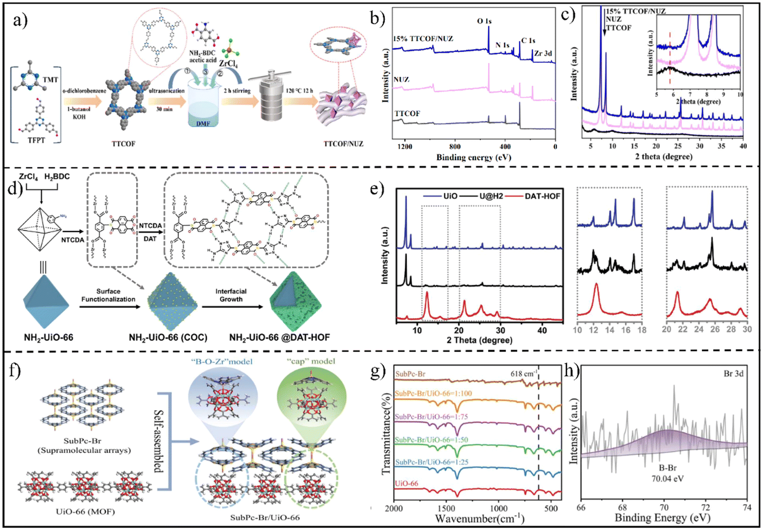 | ||
| Fig. 9 (a) Illustration of the preparation of the TTCOF/NUZ composite. (b) XPS survey spectra and (c) PXRD patterns of TTCOF, NUZ and TTCOF/NUZ. Reprinted with permission from ref. 64. Copyright 2022 American Chemical Society. (d) Scheme presenting the synthetic procedure for NH2-UiO-66@DAT-HOF photocatalysts. (e) XRD patterns of UiO, DAT-HOF, and the U@H2 hybrid. Reprinted with permission from ref. 87. Copyright 2022 Wiley-VCH. (f) Diagram of the synthesis of SubPc-Br/UiO-66. (g) FTIR spectra of the as-prepared samples. (h) High-resolution Br 3d XPS spectra of SubPc-Br/UiO-66. Reprinted with permission from ref. 45. Copyright 2023 Wiley-VCH. | ||
Different from COF materials, hydrogen-bonded organic frameworks (HOFs) self-assembled through hydrogen bonding have been rarely considered for photocatalytic applications due to their weak stability and low activity.101,102 To address the problems, a typical Zr-based MOF, NH2-UiO-66 (UiO), with high stability was selected as a support for coating a HOF, creating a MOF/HOF S-scheme heterojunction (Fig. 9d).87 The amino groups on UiO permitted further functionalization with naphthalenetetracarboxylic dianhydride (NTCDA) through covalently bonding.
Subsequently, the heterogeneous nucleation and growth of a highly stable diamino triazole-type multi-site hydrogen-bonded HOF (DAT-HOF) were induced on the surface of the UiO host. As a result, NH2-UiO-66@DAT-HOF (U@H2) core–shell hybrid materials were generated, as evidenced from the XRD pattern (Fig. 9e).
Among the diverse organic semiconductor materials, subphthalocyanines (SubPcs) are an uncommon type of coupled aromatic molecule. The solid tetrahedral structure and 14-π electron conjugation endows them with not only high response to visible light, but also superior photoelectric and thermal stability. On this basis, Ma et al. reported an H12SubPcB-Br (SubPc-Br)/UiO-66 S-scheme heterojunction synthesized by a solvothermal route.45 As seen in Fig. 9f, the supramolecular array of SubPc-Br was dynamically assembled with UiO-66 through the dynamic connection models of “B–O–Zr” and “cap” moieties. The Fourier transform infrared (FTIR) spectra (Fig. 9g) and high-resolution Br 3d XPS spectra (Fig. 9h) clearly demonstrated the formation of a SubPc-Br/UiO-66 heterojunction.
4.2 MOF-on-MOF heterojunction
The explosive expansion of the MOF field generates a distinctive class of MOF-on-MOF heterostructures by conjugating two or more different MOFs.103 More importantly, when applying such a design for constructing MOF-on-MOF heterojunctions, abundant interfacial chemical bonds can be formed via the interaction between exposed metals and/or ligands of the MOF units, which are highly conducive for electron transfer and charge separation, beyond the conventional MOF/non-MOF hybridization at a single MOF level to some extent.37,104 A typical example is that the Yu and Liu group reported an MIL-125-NH2@CoFe Prussian blue analogue (PBA) S-scheme heterojunction with a well-defined Ti–O–Co-bonded interface and an internal electric field.44 Starting with MIL-125-NH2 as the host material, an MIL-125-NH2@ cobalt-based zeolite imidazole framework (ZIF-67) heterostructure was fabricated by selective deposition of ZIF-67 nanocrystals on the top and down surfaces of MIL-125-NH2 cakes due to the facet-dependent electrostatic interaction. Afterwards, the MIL-125-NH2@CoFe PBA heterojunction was generated via a ligand exchange treatment of MIL-125-NH2@ZIF-67 in [Fe(CN)6]3− solution, where the ZIF-67 was selectively transformed into CoFe PBA (Fig. 10a). The scanning electron microscopy (SEM), transmission electron microscopy (TEM), high-angle annular dark-field scanning transmission electron microscopy (HAADF-STEM) and corresponding elemental mapping images (Fig. 10b–e) revealed a sandwich-like morphology of MIL-125-NH2@CoFe PBA with hollow CoFe PBA nanocages selectively assembled on the top-down surfaces of MIL-125-NH2 nanocakes. Fig. 10f and g show the synchrotron X-ray absorption fine structure (XAFS) profiles, verifying the formation of Ti–O–Co chemical bonds within the MOF-on-MOF heterojunction. As another example of MOF-on-MOF heterojunctions, a unique MIL-100(Fe)/NH2-MIL-125(Ti) heterojunction was also prepared by a facile ball-milling approach.105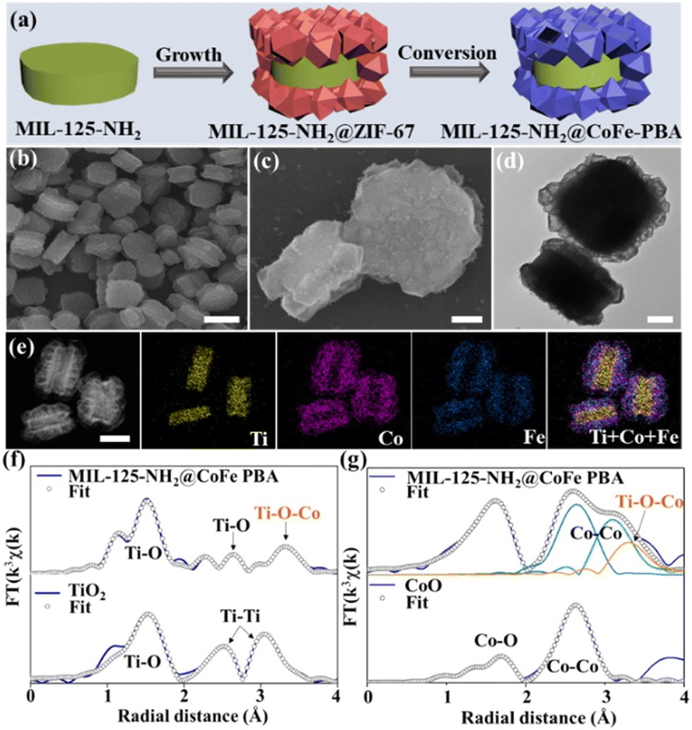 | ||
| Fig. 10 (a) Illustration of the synthesis process of MIL-125-NH2@CoFe PBA. (b and c) SEM, (d) TEM, (e) HAADF-STEM and the corresponding elemental mapping images. Scale bars are: (b), 1 μm; (e), 500 nm; and (c and d), 200 nm. (f) Ti coordination environments of MIL-125-NH2@CoFe PBA and TiO2 and (g) Co coordination environments of MIL-125-NH2@CoFe PBA and CoO. Reprinted with permission from ref. 44. Copyright 2023 Wiley-VCH. | ||
4.3 MOF derivative-based heterojunctions
As well as for direct use, MOFs are also ideal templates or precursors for the preparation of derived functional materials, such as carbon, metal compounds (e.g., metal oxides,106–108 metal sulfides,109,110 metal phosphides111,112) and their composites, via thermal and/or chemical treatments. Compared with pristine MOFs, MOF derivatives usually possess higher chemical stability, stronger light harvesting and charge transfer ability, and thus have been considered a promising class of photocatalysts.113,114 Naturally, the design of MOF-derived S-scheme heterojunctions has also witnessed great advances.115,116 For example, S-scheme In2O3/ZnO nanotubes were synthesized by using ln-MIL-68 as the precursor through a two-step annealing immersion process, as illustrated in Fig. 11a.106 Also using MIL-68-derived In2O3 as a semiconductor, the interfacial growth of CaIn2S4, MnIn2S4 or ZnIn2S4 produced three kinds of S-scheme heterojunctions (Fig. 11b).107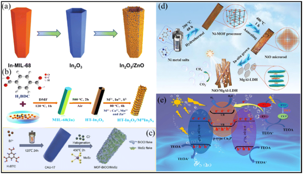 | ||
| Fig. 11 (a) Schematic illustration of the preparation of tubular In2O3/ZnO heterostructures. Reprinted with permission from ref. 106. Copyright 2023 Wiley-VCH. (b) Schematic representation of the synthetic pathway of the HT-In2O3/MIIIn2S4 (M = Ca, Mn, and Zn) heterostructure. Reprinted with permission from ref. 107. Copyright 2022 American Chemical Society. (c) Schematic illustration of the synthesis of MOF-BiOCl/MoS2 composites. Reprinted with permission from ref. 117. Copyright 2022 Elsevier. (d) Schematic diagram of the fabrication process of NiO/MgAl-LDH photocatalysts. Reprinted with permission from ref. 108. Copyright 2023 Elsevier. (e) Illustration of the CoP/Cu3P/Ni2P S-scheme heterojunction. Reprinted with permission from ref. 112. Copyright 2022 American Chemical Society. | ||
Additionally, through a sequential hydrothermal halogenation treatment, a 3D MOF-derived heterojunction assembled from BiOCl nanosheets and MoS2 nanosheets was fabricated by using CAU-17 (CAU = Christian-Albrechts-Universität) as the Bi precursor (Fig. 11c).117 In 2023, the Yang group developed a novel NiO/MgAl-LDH heterojunction photocatalyst in gas–solid mode by a two-step hydrothermal process (Fig. 11d). The heterojunction was composed of p-type NiO porous microrods derived from a Ni-MOF by calcination in air and n-type MgAl-LDH nanoplates via in situ growth on NiO.108 Apart from metal oxides, MOF-derived metal phosphide-based S-scheme heterojunctions were also reported by Jin and coauthors recently (Fig. 11e). Furthermore, in their work, ZIF-67-derived CoP/Cu3P/Ni2P (CCNP) double S-scheme photocatalytic systems were constructed by simple hydrothermal and phosphating processes.112
5. Application of S-scheme heterojunction photocatalysts
5.1 Photocatalytic hydrogen evolution
H2 as a clean fuel is expected to be an ideal alternative to fossil fuels in the future.35,118 So far, various methods including steam reforming, electrolysis, hydrocarbon pyrolysis and photocatalysis have been reported to produce H2.119,120 Among them, the photocatalytic hydrogen evolution reaction (PHER) has gained significant attention, where the development of efficient photocatalysts is the central task.121,122 Recently, MOF-based S-scheme heterojunctions have been applied in PHER with considerable success.84,86,112 For instance, Jin et al. prepared a Co3S4/Mo2S3 S-scheme heterojunction for PHER via a stepwise hydrothermal method using ZIF-67 as the template (Fig. 12a).109 Benefiting from the promoted charge transfer, the H2 evolution amount of Co3S4@Mo2S3-9 (375.37 μmol) was about 7 and 3 times higher than those of pure Mo2S3 (53.85 μmol) and Co3S4 (114.44 μmol) (Fig. 12b).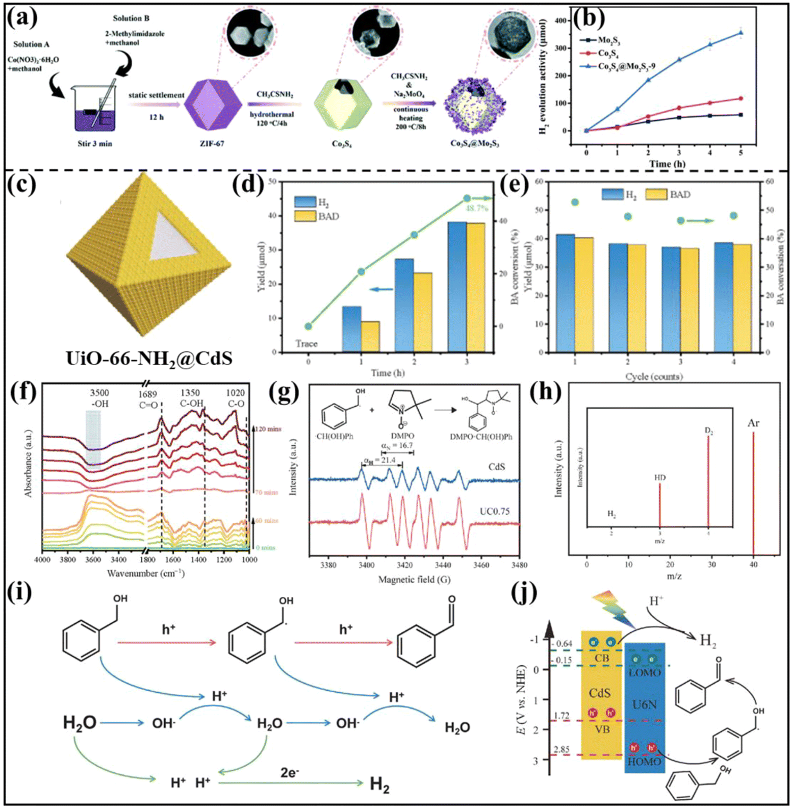 | ||
| Fig. 12 (a) Schematic diagram of the preparation process of rhombic dodecahedral Co3S4@Mo2S3. (b) Hydrogen production activities of Co3S4, Mo2S3, Co3S4@Mo2S3-9. Reprinted with permission from ref. 109. Copyright 2022 Wiley-VCH. (c) Schematic of the UC composite. (d) Hourly photocatalytic performance. (e) Photocatalytic cycle test of the UC0.75 composite. (f) In situ DRIFTS spectra of the adsorbed BA aqueous solution on the UC0.75 composite under dark and irradiated conditions. (g) EPR spectra of CdS and the UC0.75 composite in CH3CN solution (containing BA) with the addition of DMPO. (h) Mass spectrum of the gaseous products of PHER on UC0.75 using isotope-labelled D2O and BA as reactants. (i and j) Reaction mechanism for photocatalytic BA conversion and H2 evolution over the CdS/U6N S-scheme heterojunction. Reprinted with permission from ref. 81. Copyright 2022 Elsevier. | ||
To promote the simultaneous utilization of photogenerated electrons and holes, Xu and co-authors reported the synthesis of a UiO-66-NH2 (U6N)/CdS S-scheme heterojunction (denoted as UC) (Fig. 12c) for efficient H2 generation coupled with selective oxidation of benzyl alcohol (BA) under light irradiation.81 After illumination for 3 h, the heterojunction with the optimized UiO-66-NH2/CdS ratio (UC0.75) delivered a high H2 production amount of 38.1 μmol and a benzaldehyde (BAD) yield of 37.8 μmol, superior to the single-component UiO-66-NH2 and CdS (Fig. 12d). As well as high activity, UC0.75 also exhibited excellent photocatalytic stability with almost no performance decline after four consecutive cycles (Fig. 12e). In situ diffuse reflectance infrared Fourier transform spectroscopy (DRIFTS) was used to monitor the functional group changes in the adsorbed species on the surface of the photocatalyst during the photocatalytic reaction (Fig. 12f). The results showed that BA was dehydrogenated and oxidized into benzaldehyde (BAD) with the detection of a radical intermediate of ˙CH(OH)Ph (Fig. 12g). Using isotope-labelled heavy water (D2O) and BA as reactants, the gaseous products were found to be mainly D2 and HD, suggesting that the hydrogen protons in the coupling reaction system came from H2O. Collectively, the reaction mechanism of photocatalytic H2 production and coupled BA conversion to BAD over CdS/U6N heterojunction was depicted in Fig. 12i. Under illumination, the photogenerated holes located in U6N reacted first with benzyl alcohol to oxidize α-C on benzyl alcohol to produce ˙CH(OH)Ph, which was then converted to BAD by further oxidation. Meanwhile, the photogenerated electrons in CdS reduced the generated H+ to form H2 (Fig. 12j).
5.2 Photocatalytic CO2 reduction
Photocatalytic CO2 reduction for valuable chemical and fuel production is of great significance for achieving carbon neutrality goals. Nevertheless, the stable molecular structure of CO2 with a high bonding energy of CO bonds (750 kJ mol−1) limits the practical application of photocatalytic CO2 reduction.47,49,123 To resolve the problem, Jing et al. synthesized a single-atom Ni@MOF/BiVO4(Ni@MOF/BVO) S-scheme heterojunction. NTU-9 (NTU = Nanyang Technological University) with a 2D honeycomb structure was synthesized for immobilization of abundant single Ni(II) sites.124
The resulting Ni@MOF was coupled with BVO nanosheets by H-bonding-induced assembly, resulting in Ni@MOF/BVO 2D heterojunctions with wide-spectrum absorption (Fig. 13a). The photocatalytic performance for CO2 reduction was assessed in pure water. By carefully altering the loading amounts of the MOF and Ni, the optimized sample produced the largest CO amount of 178 μmol g−1 with a CO selectivity of 99.2% and O2 as the oxidative product. The CO2 photoconversion is 66-fold that of the reference BVO nanoparticles. In contrast, the physically mixed sample without favourable interfacial bonding demonstrated negligible photoactivity enhancement compared with BVO. To avoid the interference of organic impurities, photoreduction of 13C-labled CO2 was further conducted over the Ni@6MOF/BVO photocatalyst. The gas chromatography-mass spectrum (Fig. 13c) showed peaks assigned to 13CH4 and 13CO, indicating that the products were evolved from the photoreduction of 13CO2. Under UV-vis light irradiation, the photoelectrons could transfer from BVO to the MOF and then directionally to single Ni(II) sites. The holes of BVO would oxidize water to produce O2 and the electrons would reduce the adsorbed CO2 by single Ni atoms along with vicinal hydroxyl groups to produce CO (Fig. 13d).
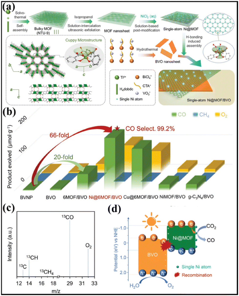 | ||
| Fig. 13 (a) Synthetic illustration of the single-atom Ni@MOF/BVO heterojunction photocatalyst. (b) Photoactivities of BVNP, BVO, 6MOF/BVO, Ni@6MOF/BVO, Cu@6MOF/BVO, NiMOF/BVO, and g-C3N4/BVO for CO2 reduction. (c) Mass spectrum of the products over Ni@6MOF/BVO in the photocatalytic reduction of 13CO2. (d) Illustration of the proposed photocatalytic mechanism of Ni@6MOF/BVO based on S-scheme charge transfer for CO2 conversion under UV-vis light irradiation. Reprinted with permission from ref. 124. Copyright 2022 Wiley-VCH. | ||
5.3 C–H functionalization
Photocatalysis driven C–H functionalization is an important direction in organic synthesis toward heterocyclic compounds.125,126 Very recently, a MOF-based S-scheme heterojunction was applied for activating C–H bonds with superior performance by Yu and colleagues.46 In their work, S-scheme heterojunctions composed of titanium–organic frameworks, MOF-902@thiophene-based covalent triazine frameworks (CTF-Th), were synthesized by growth of MOF-902 on preformed CTF-Th (Fig. 14a). The obtained heterojunction exhibited interfacial Ti–S bonds and controllable oxygen vacancies (OVs). The MOF-902@CTF-Th1.5 heterojunction with a MOF-902@CTF-Th mass ratio of 1.5 was identified as the optimal sample, showing the highest efficiency of 98% in the photocatalytic C3-acylation of indoles. The product yield was calculated to be 8.2 times larger than that of pristine CTF-Th or MOF-902 (Fig. 14b). Furthermore, the constructed platform was versatile, which could extend the scope of substrates to 15 different examples. The origin of the excellent performance was ascribed to the enhanced interfacial charge separation and transfer by introducing Ti–S bonds and moderate OVs. This promoted the activation of molecular oxygen into ˙O2− and 1O2 by photogenerated electrons, which accounted for the formation of targeted 3-benzoylindole by their reaction with phenylglyoxylic acid and indole (Fig. 14c).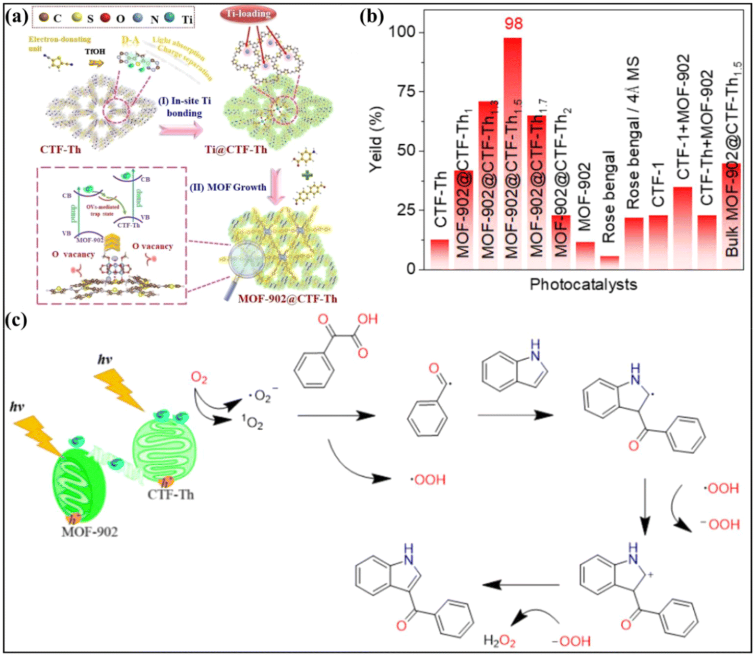 | ||
| Fig. 14 (a) Schematic presentation of the synthetic route of the MOF-902@CTF-Th heterostructure. (b) Decarboxylative C3-acylation of indoles of different photocatalysts. (c) Proposed reaction mechanism for decarboxylative C3-acylation of indoles in the presence of the MOF-902@CTF-Th photocatalyst. Reprinted with permission from ref. 46. Copyright 2023 Wiley-VCH. | ||
5.4 H2O2 production
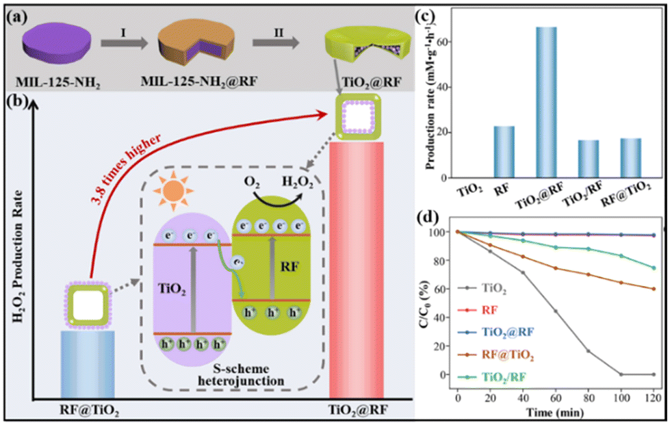
Hydrogen peroxide (H2O2), as a green oxidant, plays irreplaceable roles in various important applications.127–130 The photocatalytic two-electron oxygen reduction reaction (2e-ORR) has recently emerged as a promising alternative route to the traditional anthraquinone oxidation process.131,132 To date, great efforts have been devoted to designing high-performance 2e-ORR photocatalysts, however, the investigation of MOF-based S-scheme heterojunctions for H2O2 production is rare.As a typical example, the Yu group reported an S-scheme heterojunction by coupling MIL-125-NH2-derived TiO2 and an organic semiconductor, resorcinol–formaldehyde (RF) resin.133 Notably, two types of core–shell TiO2@RF and RF@TiO2 photocatalysts were prepared with TiO2 nanocrystals deposited on the interior and exterior surfaces of a hollow RF shell, respectively, to study the impact of spatial arrangement (Fig. 15a). When used as a 2e-ORR photocatalyst for H2O2 production, the TiO2@RF heterojunction delivered a high H2O2 yield of 66.6 mM g−1 h−1 in pure water, significantly outperforming single RF, TiO2 and the RF@TiO2 counterpart (Fig. 15b, c and d). The possible reason for the enhanced performance of TiO2@RF may be ascribed to the design of S-scheme heterojunctions with a specific spatial configuration, enabling maximally preserved redox ability, promoted charge separation and active site exposure, and restricted H2O2 decomposition.
 | ||
| Fig. 15 Illustration of (a) the synthesis of the TiO2@RF S-scheme heterostructure and (b) H2O2 production rates of TiO2@RF and RF@TiO2 photocatalysts with reversed spatial arrangements. (c) H2O2 production rates and (d) photocatalytic H2O2 decomposition rates over TiO2@RF, RF@TiO2, RF, TiO2, and TiO2/RF. Reprinted with permission from ref. 133. Copyright 2023 Wiley-VCH. | ||
5.5 Wastewater treatment
As well as producing valuable chemicals, photocatalysis also affords an efficient route for wastewater treatment.134–136 Compared to single-component semiconductors, S-scheme heterojunctions usually exhibited higher activity for pollutant degradation.44,82,137,138 For instance, Neppolian et al. developed a Cu-BTC (a copper-based MOF)@ZnWO4 S-scheme heterojunction via an ultrasound-assisted hydrothermal strategy.138 Under simultaneous visible-light irradiation and ultrasound conditions, the Cu-BTC/ZnWO4 heterojunction completely removed the tetracycline (TC, a typical type of antibiotic) within 60 min (Fig. 16a). The kinetic constant value of the Cu-BTC/ZnWO4 heterojunction was estimated to be 0.04908 min−1, much higher than those of Cu-BTC (0.00695 min−1) and ZnWO4 (0.01057 min−1), indicating the superior sonophotocatalytic activity of the Cu-BTC/ZnWO4 heterojunction ascribed to the S-scheme charge transfer (Fig. 16b and c).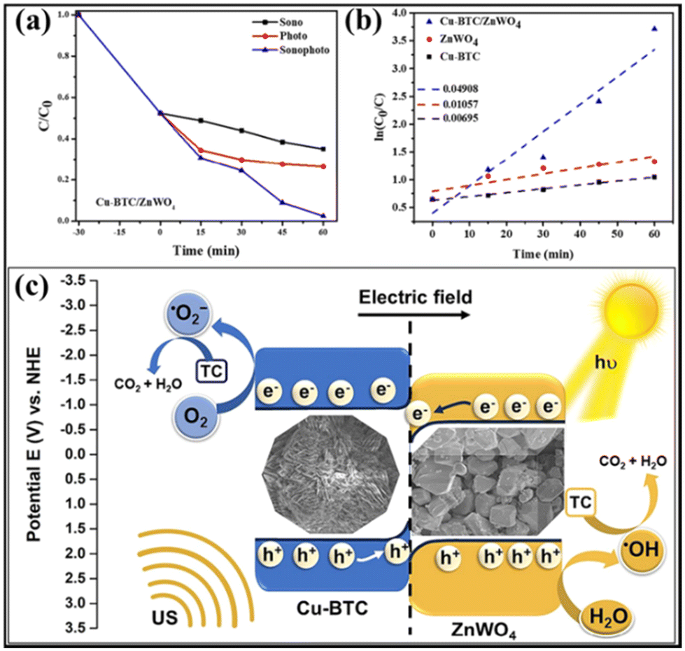 | ||
| Fig. 16 (a) Analysis of Cu-BTC/ZnWO4 using C/C0 plots for sono-, photo-, and sonophotocatalytic processes. (b) Kinetic studies of Cu-BTC, ZnWO4, and Cu-BTC/ZnWO4. (c) Schematic illustration depicting the degradation of TC using sonophotocatalysis on Cu-BTC/ZnWO4 S-scheme photocatalysts. Reprinted with permission from ref. 138. Copyright 2023 Elsevier. | ||
Different from the aforementioned TC degradation process with the aid of sonication, Bao and co-workers reported the simultaneous TC removal and H2O2 production over an S-type heterojunction, which was synthesized by growing Bi2O3 nanocrystals and NH2-MIL-101 (an iron-based MOF) onto surface-modified g-C3N4 (the resulting heterojunction was named NMB).139 As shown in Fig. 17a, the H2O2 generation amount of the optimized sample 10%-NMB reached 655.63 μmol g−1 after light irradiation for 120 min in the absence of TC, outperforming those of Bi2O3 and the NH2-MIL-101(Fe)/C3N4 composite. Moreover, the TC degradation efficiency of the photocatalysts was further explored. As can be seen, the ternary 10%-NMB demonstrated the highest photocatalytic activity with 100% degradation of TC within 50 min (Fig. 17b and c).
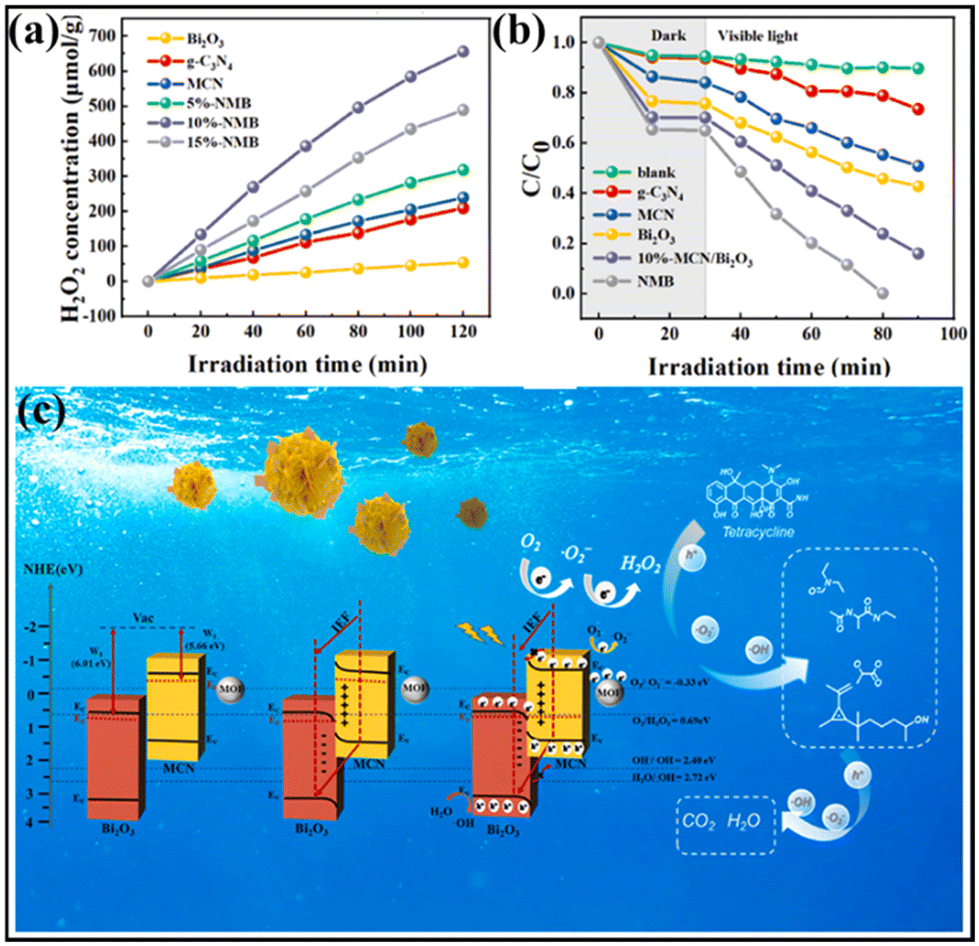 | ||
| Fig. 17 (a) Degradation performance of TC using various photocatalysts. (b) H2O2 production performances of different photocatalysts. (c) Illustration of the proposed photocatalytic mechanism of 10%-NMB based on S-scheme charge transfer for the degradation of TC. Reprinted with permission from ref. 139. Copyright 2023 Elsevier. | ||
6. Conclusions and outlook
In summary, MOFs as an important family of porous crystalline materials have demonstrated outstanding performances in many fields.14 However, their photocatalytic performance has been seriously restricted by their relatively weak light absorption capacity, rapid recombination of photogenerated charges and limited redox ability. Construction of MOF-based S-scheme heterojunction photocatalysts provides an efficient strategy to enhance the light harvesting ability, improve the electron–hole separation efficiency and maximize the redox capability, endowing MOFs with improved photocatalytic properties. This work reviews the latest progress of MOF-based S-scheme photocatalysts with respect to their synthesis, structures and applications. Although significant advances have been achieved in this emerging field, there are still several challenges for further investigations.Firstly, from a morphological aspect, most of the reported MOF-based photocatalysts exhibited a micropore-dominated structure, preventing the active site accessibility and mass transfer. To address these problems, introducing hierarchical pores (e.g. mesopores and macropores) or construction of complex architectures (e.g. hollow or open-frame-like structures) in MOF-based semiconductors is feasible.140–142 In this regard, synthetic strategies including selective etching, defect engineering and template methods are suggested.82,143,144
Secondly, compared to the huge number of reported semiconducting materials, those used for preparing MOF-based S-scheme heterojunctions are limited. The involved materials are mainly metal oxides, metal sulphides or carbon-based materials. Further incorporation of other promising photocatalysts such as metal nitrides,145,146 bismuth oxyhalides147,148 and metal selenides149,150 will undoubtedly offer new opportunities for developing efficient MOF-based S-scheme heterojunctions. Beyond MOF/non-MOF combinations, the design of MOF-on-MOF heterojunctions is expected to demonstrate additional merits as mentioned before, while has been rarely studied.
Finally, from the application perspective, an in-depth understanding of the underlying structure–performance relationship of MOF-based S-scheme heterojunctions is highly desired. In situ characterization methods such as Raman spectroscopy, infrared spectroscopy, XRD, XPS and TEM can serve as powerful tools for monitoring the composition and structure evolution of the photocatalysts during photochemical processes. Besides, to fully implement the MOF-based S-scheme heterojunctions, the simultaneous utilization of photogenerated holes and electrons for the coupled redox reaction toward high-value chemical production is of great significance.151,152 Moreover, microporosity as one of the most important features of MOFs determines the reactant transport during photocatalysis. Therefore, the investigation of the pore connectivity throughout the interface between different materials is a crucial issue, which has rarely been reported. Another crucial step for their practical application is constructing MOF-based S-scheme heterojunctions at the macroscopic scale with the forms of gel, film or membrane.153,154
It is believed that the further expansion of MOF-based S-scheme heterojunction photocatalysts from the above directions will promote the application of photocatalysis technology in various important fields.
Conflicts of interest
There are no conflicts to declare.Acknowledgements
The authors acknowledge the support from the National Natural Science Foundation of China (NSFC 51908218 and 21905092), the Scientific Research Foundation of Shanghai Institute of Technology (10120K226156-A06-YJ2022-62), the Shanghai Higher Education Institution Young Teacher Training Funding Program (ZZ202312031) and the Key Laboratory of Jiangsu Province for Chemical Pollution Control and Resources Reuse (Nanjing University of Science and Technology).References
- N. Keller, J. Ivanez, J. Highfield and A. M. Ruppert, Appl. Catal., B, 2021, 296, 120320 CrossRef CAS.
- L. Lu, M. Sun, T. Wu, Q. Lu, B. Chen, C. H. Chan, H. H. Wong and B. Huang, Small Methods, 2023, 7, 2300430 CrossRef CAS PubMed.
- B. Zhu, J. Sun, Y. Zhao, L. Zhang and J. Yu, Adv. Mater., 2023, 2310600 Search PubMed.
- Y. Song, X. Zheng, Y. Yang, Y. Liu, J. Li, D. Wu, W. Liu, Y. Shen and X. Tian, Adv. Mater., 2023, 2305835 CrossRef PubMed.
- L. Wang, X. Zheng, L. Chen, Y. Xiong and H. Xu, Angew. Chem., Int. Ed., 2018, 57, 3454–3458 CrossRef CAS PubMed.
- X. Ruan, S. Li, C. Huang, W. Zheng, X. Cui and S. K. Ravi, Adv. Mater., 2023, 2305285 CrossRef PubMed.
- C. Foo, Y. Li, K. Lebedev, T. Chen, S. Day, C. Tang and S. C. E. Tsang, Nat. Commun., 2021, 12, 661 CrossRef CAS PubMed.
- Z. Wei, S. Zhao, W. Li, X. Zhao, C. Chen, D. L. Phillips, Y. Zhu and W. Choi, ACS Catal., 2022, 12, 11436–11443 CrossRef CAS.
- X. Zheng, Y. Song, Y. Liu, Y. Yang, D. Wu, Y. Yang, S. Feng, J. Li, W. Liu, Y. Shen and X. Tian, Coord. Chem. Rev., 2023, 475, 214898 CrossRef CAS.
- Y. Wang, S. Wang and X. W. Lou, Angew. Chem., Int. Ed., 2019, 58, 17236–17240 CrossRef CAS PubMed.
- G. Yan, X. Sun, K. Zhang, Y. Zhang, H. Li, Y. Dou, D. Yuan, H. Huang, B. Jia, H. Li and T. Ma, Small, 2022, 18, 2201340 CrossRef CAS PubMed.
- X. Chen and K. M. Ok, Chem. Sci., 2022, 13, 3942–3956 RSC.
- X. Feng, R. Zheng, C. Gao, W. Wei, J. Peng, R. Wang, S. Yang, W. Zou, X. Wu, Y. Ji and H. Chen, Nat. Commun., 2022, 13, 2146 CrossRef CAS PubMed.
- F. He, Y. Lu, Y. Wu, S. Wang, Y. Zhang, P. Dong, Y. Wang, C. Zhao, S. Wang, J. Zhang and S. Wang, Adv. Mater., 2023, 2307490 CrossRef PubMed.
- L. Sun, D. Wang, Y. Li, B. Wu, Q. Li, C. Wang, S. Wang and B. Jiang, Chin. Chem. Lett., 2023, 34, 107490 CrossRef CAS.
- M. Traxler, S. Gisbertz, P. Pachfule, J. Schmidt, J. Roeser, S. Reischauer, J. Rabeah, B. Pieber and A. Thomas, Angew. Chem., Int. Ed., 2022, 61, e202117738 CrossRef CAS PubMed.
- C. Wu, X. Li, M. Shao, J. Kan, G. Wang, Y. Geng and Y. B. Dong, Chin. Chem. Lett., 2022, 33, 4559–4562 CrossRef CAS.
- A. Dhakshinamoorthy, A. M. Asiri and H. García, Angew. Chem., Int. Ed., 2016, 55, 5414–5445 CrossRef CAS PubMed.
- J. Chen, R. Abazari, K. A. Adegoke, N. W. Maxakato, O. S. Bello, M. Tahir, S. Tasleem, S. Sanati, A. M. Kirillov and Y. Zhou, Coord. Chem. Rev., 2022, 469, 214664 CrossRef CAS.
- C. Liu, J. Wang, J. Wan and C. Yu, Coord. Chem. Rev., 2021, 432, 213743 CrossRef CAS.
- Y. Li, Y. Wei, W. He, Z. Tang, J. Xiong and Z. Zhao, Chin. Chem. Lett., 2023, 34, 108417 CrossRef CAS.
- L. Jiao and H. L. Jiang, Chin. J. Catal., 2023, 45, 1–5 CrossRef CAS.
- H. Sepehrmansourie, H. Alamgholiloo, N. Noroozi Pesyan and M. A. Zolfigol, Appl. Catal., B, 2023, 321, 122082 CrossRef CAS.
- C. Zhang, C. Xie, Y. Gao, X. Tao, C. Ding, F. Fan and H. L. Jiang, Angew. Chem., Int. Ed., 2022, 61, e202204108 CrossRef CAS PubMed.
- N. Y. Huang, Y. T. Zheng, D. Chen, Z. Y. Chen, C. Z. Huang and Q. Xu, Chem. Soc. Rev., 2023, 52, 7949–8004 RSC.
- Z. Jiang, X. Xu, Y. Ma, H. S. Cho, D. Ding, C. Wang, J. Wu, P. Oleynikov, M. Jia, J. Cheng, Y. Zhou, O. Terasaki, T. Peng, L. Zan and H. Deng, Nature, 2020, 586, 549–554 CrossRef CAS PubMed.
- X. Gong, Y. Shu, Z. Jiang, L. Lu, X. Xu, C. Wang and H. Deng, Angew. Chem., Int. Ed., 2020, 59, 5326–5331 CrossRef CAS PubMed.
- J. Xiao, R. Li and H. Jiang, Small Methods, 2023, 7, 2201258 CrossRef CAS PubMed.
- L. Sun, Y. Yuan, F. Wang, Y. Zhao, W. Zhan and X. J. N. E. Han, Nano Energy, 2020, 74, 104909 CrossRef CAS.
- L. Liu, S. Du, X. Guo, Y. Xiao, Z. Yin, N. Yang, Y. Bao, X. Zhu, S. Jin and Z. Feng, J. Am. Chem. Soc., 2022, 144, 2747–2754 CrossRef CAS PubMed.
- M. Li, X. Liu, Y. Che, H. Xing, F. Sun, W. Zhou and G. Zhu, Angew. Chem., Int. Ed., 2023, 62, e202308651 CrossRef CAS PubMed.
- S. Navalón, A. Dhakshinamoorthy, M. Álvaro, B. Ferrer and H. García, Chem. Rev., 2023, 123, 445–490 CrossRef PubMed.
- Y. Qian, F. Zhang and H. Pang, Adv. Funct. Mater., 2021, 31, 2104231 CrossRef CAS.
- Y. Li, J. Zhang, Q. Chen, X. Xia and M. Chen, Adv. Mater., 2021, 33, 2100855 CrossRef CAS PubMed.
- C. Liu, Q. Sun, L. Lin, J. Wang, C. Zhang, C. Xia, T. Bao, J. Wan, R. Huang, J. Zou and C. Yu, Nat. Commun., 2020, 11, 4971 CrossRef CAS PubMed.
- H. Peng, J. Raya, F. Richard, W. Baaziz, O. Ersen, A. Ciesielski and P. Samorì, Angew. Chem., Int. Ed., 2020, 59, 19602–19609 CrossRef CAS PubMed.
- W. Han, L. H. Shao, X. J. Sun, Y. H. Liu, F. M. Zhang, Y. Wang, P. Y. Dong and G. L. Zhang, Appl. Catal., B, 2022, 317, 121710 CrossRef CAS.
- J. Wang, Y. Mao, R. Zhang, Y. Zeng, C. Li, B. Zhang, J. Zhu, J. Ji, D. Liu and R. Gao, Adv. Sci., 2022, 9, 2204036 CrossRef CAS PubMed.
- H. Yang, C. Yang, N. Zhang, K. Mo, Q. Li, K. Lv, J. Fan and L. Wen, Appl. Catal., B, 2021, 285, 119801 CrossRef CAS.
- W. Shi, Y. Fu, H. Sun, X. Sun, C. Hao, F. Guo and Y. Tang, Inorg. Chem. Commun., 2022, 146, 110140 CrossRef CAS.
- R. Wang, Z. Wang, X. Shang, Y. Yang, J. Ding and Q. Zhong, J. Mater. Chem. A, 2023, 11, 630–641 RSC.
- Z. Jin, Y. Li and Q. Ma, Trans. Tianjin Univ., 2021, 27, 127–138 CrossRef CAS.
- M. D. Goudarzi, N. Khosroshahi, A. Hamlehdar and V. Safarifard, J. Environ. Chem. Eng., 2023, 11, 110169 CrossRef CAS.
- L. Yuan, C. Zhang, Y. Zou, T. Bao, J. Wang, C. Tang, A. Du, C. Yu and C. Liu, Adv. Funct. Mater., 2023, 2214627 CrossRef CAS.
- Z. Zheng, B. Wang, Z. Li, H. Hao, C. Wei, W. Luo, L. Jiao, S. Zhang, B. Zhou and X. Ma, Small, 2023, 2306820 Search PubMed.
- Z. Gao, Y. Jian, S. Yang, Q. Xie, C. J. Ross Mcfadzean, B. Wei, J. Tang, J. Yuan, C. Pan and G. Yu, Angew. Chem., Int. Ed., 2023, e202304173 CAS.
- L. Zhang, J. Zhang, H. Yu and J. Yu, Adv. Mater., 2022, 34, 2107668 CrossRef CAS PubMed.
- Q. Xu, L. Zhang, B. Cheng, J. Fan and J. Yu, Chem, 2020, 6, 1543–1559 CAS.
- L. Wang, B. Zhu, J. Zhang, J. B. Ghasemi, M. Mousavi and J. Yu, Matter, 2022, 5, 4187–4211 CrossRef CAS.
- J. Low, J. Yu, M. Jaroniec, S. Wageh and A. A. Al-Ghamdi, Adv. Mater., 2017, 29, 1601694 CrossRef PubMed.
- H. Zhou, Y. Qu, T. Zeid and X. Duan, Energy Environ. Sci., 2012, 5, 6732–6743 RSC.
- H. Wang, L. Zhang, Z. Chen, J. Hu, S. Li, Z. Wang, J. Liu and X. Wang, Chem. Soc. Rev., 2014, 43, 5234–5244 RSC.
- C. Xu, P. Ravi Anusuyadevi, C. Aymonier, R. Luque and S. Marre, Chem. Soc. Rev., 2019, 48, 3868–3902 RSC.
- P. Zhou, J. Yu and M. Jaroniec, Adv. Mater., 2014, 26, 4920–4935 CrossRef CAS PubMed.
- H. Tada, T. Mitsui, T. Kiyonaga, T. Akita and K. Tanaka, Nat. Mater., 2006, 5, 782–786 CrossRef CAS PubMed.
- X. Li, C. Garlisi, Q. Guan, S. Anwer, K. Al-Ali, G. Palmisano and L. Zheng, Mater. Today, 2021, 47, 75–107 CrossRef CAS.
- J. Low, C. Jiang, B. Cheng, S. Wageh, A. A. Al-Ghamdi and J. Yu, Small Methods, 2017, 1, 5 CrossRef.
- B. J. Ng, L. K. Putri, X. Y. Kong, Y. W. Teh, P. Pasbakhsh and S. P. Chai, Adv. Sci., 2020, 7, 7 Search PubMed.
- S. T. Kochuveedu, Y. H. Jang and D. H. Kim, Chem. Soc. Rev., 2013, 42, 8467–8493 RSC.
- K. E. Byun, H. J. Chung, J. Lee, H. Yang, H. J. Song, J. Heo, D. H. Seo, S. Park, S. W. Hwang, I. Yoo and K. Kim, Nano Lett., 2013, 13, 4001–4005 CrossRef CAS PubMed.
- F. Ou, D. B. Buchholz, F. Yi, B. Liu, C. Hseih, R. P. H. Chang and S. T. Ho, ACS Appl. Mater. Interfaces, 2011, 3, 1341–1345 CrossRef CAS PubMed.
- P. Hao, Z. Chen, Y. Yan, W. Shi and F. Guo, Sep. Purif. Technol., 2024, 330, 125302 CrossRef CAS.
- F. He, B. Zhu, B. Cheng, J. Yu, W. Ho and W. Macyk, Appl. Catal., B, 2020, 272, 119006 CrossRef CAS.
- Q. Niu, S. Dong, J. Tian, G. Huang, J. Bi and L. Wu, ACS Appl. Mater. Interfaces, 2022, 14, 24299–24308 CrossRef CAS PubMed.
- T. Li, N. Tsubaki and Z. Jin, J. Mater. Sci. Technol., 2024, 169, 82–104 CrossRef.
- P. Hu, G. Liang, B. Zhu, W. Macyk, J. Yu and F. Xu, ACS Catal., 2023, 13, 12623–12633 CrossRef CAS.
- C. Cheng, B. He, J. Fan, B. Cheng, S. Cao and J. Yu, Adv. Mater., 2021, 33, 2100317 CrossRef CAS PubMed.
- P. Chang, Y. Wang, Y. Wang and Y. J. Zhu, Chem. Eng. J., 2022, 450, 137804 CrossRef CAS.
- B. Xia, B. He, J. Zhang, L. Li, Y. Zhang, J. Yu, J. Ran and S. Z. Qiao, Adv. Energy Mater., 2022, 12, 2201449 CrossRef CAS.
- Y. Huang, F. Mei, J. Zhang, K. Dai and G. Dawson, Acta Phys.-Chim. Sin., 2022, 38, 2108028 Search PubMed.
- F. Li, G. Zhu, J. Jiang, L. Yang, F. Deng and X. Li, J. Mater. Sci. Technol., 2023, 177, 142–180 CrossRef.
- X. Chen, R. Guo, W. Pan, Y. Yuan, X. Hu, Z. Bi and J. Wang, Appl. Catal., B, 2022, 318, 121839 CrossRef CAS.
- L. Wang, X. Fei, L. Zhang, J. Yu, B. Cheng and Y. Ma, J. Mater. Sci. Technol., 2022, 112, 1–10 CrossRef CAS.
- S. Li, M. Cai, C. Wang, Y. Liu, N. Li, P. Zhang and X. Li, J. Mater. Sci. Technol., 2022, 123, 177–190 CrossRef CAS.
- F. Li, X. Li, S. Tong, J. Wu, T. Zhou, Y. Liu and J. Zhang, Nano Energy, 2023, 117, 108849 CrossRef CAS.
- X. Wang, M. Sayed, O. Ruzimuradov, J. Zhang, Y. Fan, X. Li, X. Bai and J. Low, Appl. Mater. Today, 2022, 29, 101609 CrossRef.
- J. Tian, Y. Sang, Z. Zhao, W. Zhou, D. Wang, X. Kang, H. Liu, J. Wang, S. Chen, H. Cai and H. Huang, Small, 2013, 9, 3864–3872 CrossRef CAS PubMed.
- M. Sayed, B. Zhu, P. Kuang, X. Liu, B. Cheng, A. A. A. Ghamdi, S. Wageh, L. Zhang and J. Yu, Adv. Sustainable Syst., 2022, 6, 2100264 CrossRef CAS.
- H. Ren, F. Qi, A. Labidi, J. Zhao, H. Wang, Y. Xin, J. Luo and C. Wang, Appl. Catal., B, 2023, 330, 122587 CrossRef CAS.
- H. Yang, L. Jia, Q. Zhang, S. Yuan, T. Ohno and B. J. S. Xu, Small, 2023, 2308743 CrossRef PubMed.
- B. Liu, J. Cai, J. Zhang, H. Tan, B. Cheng and J. Xu, Chin. J. Catal., 2023, 51, 204–215 CrossRef CAS.
- J. Wei, Y. Chen, H. Zhang, Z. Zhuang and Y. J. Yu, Chin. J. Catal., 2021, 42, 78–86 CrossRef CAS.
- J. Sun, Y. Guan, G. Yang, S. Qiu, H. Shao, Y. Wang, G. Li and S. Xiao, ACS Sustainable Chem. Eng., 2023, 11, 14827–14840 CrossRef CAS.
- Y. Zhang, D. Lu, Z. Wang, M. Zhou, K. K. Kondamareddy, J. Li, H. Fan, D. Cao and W. Ho, Inorg. Chem. Front., 2023, 10, 6683–6700 RSC.
- C. Luo, Y. Lin, Y. Zhang, S. Zhang, S. Tong, S. Wu and C. Yang, Sep. Purif. Technol., 2023, 320, 124052 CrossRef CAS.
- Y. Quan, G. Wang, X. Wang, X. Guo, X. Hao, K. Wang and Z. Jin, Langmuir, 2022, 38, 12617–12629 CrossRef CAS PubMed.
- J. Wang, Y. Mao, R. Zhang, Y. Zeng, C. Li, B. Zhang, J. Zhu, J. Ji, D. Liu, R. Gao and Y. Ma, Adv. Sci., 2022, 9, 2204036 CrossRef CAS PubMed.
- M. R. Patel and S. K. Kailasa, ChemistrySelect, 2022, 7, e202201849 CrossRef CAS.
- Y. Wang, R. Zhang, Z. Zhang, J. Cao and T. Ma, Adv. Mater. Interfaces, 2019, 6, 1901429 CrossRef CAS.
- J. Fu, J. Yu, C. Jiang and B. Cheng, Adv. Energy Mater., 2018, 8, 1701503 CrossRef.
- S. K. Gaddam, R. Pothu and R. Boddula, Polym. Compos., 2020, 41, 430–442 CrossRef CAS.
- J. Li, L. Zhu, C. H. Tung and L. Z. Wu, Angew. Chem., Int. Ed., 2023, 62, e202301384 CrossRef CAS PubMed.
- Y. Y. Han, X. L. Lu, S. F. Tang, X. P. Yin, Z. W. Wei and T. B. Lu, Adv. Energy Mater., 2018, 8, 1702992 CrossRef.
- C. Wang, X. Han, Q. Xu, Y. N. Sun, J. Arbiol, M. N. Ghazzal and J. Li, J. Mater. Chem. A, 2023, 11, 3380–3387 RSC.
- Y. Wang, R. Hu, Y. Li, F. Wang, J. Shang and J. Shui, Nano Res., 2022, 15, 1054–1060 CrossRef CAS.
- K. Wang, X. Kong, H. Xie, S. Li, M. Wang and Z. Jin, Dalton Trans., 2023, 52, 8716–8727 RSC.
- H. Wang, H. Wang, Z. Wang, L. Tang, G. Zeng, P. Xu, M. Chen, T. Xiong, C. Zhou, X. Li, D. Huang, Y. Zhu, Z. Wang and J. Tang, Chem. Soc. Rev., 2020, 49, 4135–4165 RSC.
- A. P. Côté, A. I. Benin, N. W. Ockwig, M. O'Keeffe, A. J. Matzger and O. M. Yaghi, Science, 2005, 310, 1166–1170 CrossRef PubMed.
- Y. Zhang, H. Liu, F. Gao, X. Tan, Y. Cai, B. Hu, Q. Huang, M. Fang and X. Wang, EnergyChem, 2022, 4, 100078 CrossRef CAS.
- R. Freund, O. Zaremba, G. Arnauts, R. Ameloot, G. Skorupskii, M. Dincă, A. Bavykina, J. Gascon, A. Ejsmont, J. Goscianska, M. Kalmutzki, U. Lächelt, E. Ploetz, C. S. Diercks and S. Wuttke, Angew. Chem., Int. Ed., 2021, 60, 23975–24001 CrossRef CAS PubMed.
- R. B. Lin, Y. He, P. Li, H. Wang, W. Zhou and B. Chen, Chem. Soc. Rev., 2019, 48, 1362–1389 RSC.
- I. Hisaki, Y. Suzuki, E. Gomez, Q. Ji, N. Tohnai, T. Nakamura and A. Douhal, J. Am. Chem. Soc., 2019, 141, 2111–2121 CrossRef CAS PubMed.
- L. Mao and J. Qian, Small, 2023, 2308732 CrossRef PubMed.
- C. Liu, L. Lin, Q. Sun, J. Wang, R. Huang, W. Chen, S. Li, J. Wan, J. Zou and C. Yu, Chem. Sci., 2020, 11, 3680–3686 RSC.
- L. Wang, K. Zhang, J. Qian, M. Qiu, N. Li, H. Du, X. Hu, Y. Fu, M. Tan, D. Hao and Q. Wang, Chemosphere, 2023, 344, 140277 CrossRef CAS PubMed.
- G. Han, C. Liu, Y. Pan, W. Macyk, S. Wageh, A. A. Al-Ghamdi and F. Xu, Adv. Sustainable Syst., 2023, 7, 2200381 CrossRef CAS.
- R. Bariki, K. Das, S. K. Pradhan, B. Prusti and B. Mishra, ACS Appl. Energy Mater., 2022, 5, 11002–11017 CrossRef CAS.
- H. Yang, H. Hou, M. Yang, Z. Zhu, H. Fu, D. Zhang, Y. Luo and W. J. Yang, Chem. Eng. J., 2023, 474, 145813 CrossRef CAS.
- J. Li, M. Li and Z. Jin, Catal. Sci. Technol., 2022, 12, 1144–1158 RSC.
- X. Gui, Y. Zhou, Q. Liang, M. Zhou, X. Li, S. Xu and Z. Li, Int. J. Hydrogen Energy, 2023, 48, 38237–38250 CrossRef CAS.
- T. Li, X. Guo, L. Zhang, T. Yan and Z. Jin, Int. J. Hydrogen Energy, 2021, 46, 20560–20572 CrossRef CAS.
- K. Wang, H. Xie, Y. Li, G. Wang and Z. J. T. Jin, J. Phys. Chem. C, 2022, 126, 6947–6959 CrossRef CAS.
- J. Lin, Q. Wu, J. Qiao, S. Zheng, W. Liu, L. Wu, J. Liu and Z. Zeng, iScience, 2023, 26, 107132 CrossRef CAS PubMed.
- Y. Zhang, J. Xu, J. Zhou and L. Wang, Chin. J. Catal., 2022, 43, 971–1000 CrossRef CAS.
- S. Wang, B. Y. Guan, Y. Lu and X. W. D. Lou, J. Am. Chem. Soc., 2017, 139, 17305–17308 CrossRef CAS PubMed.
- Z. Cai, J. Dai, W. Li, K. B. Tan, Z. Huang, G. Zhan, J. Huang and Q. Li, ACS Catal., 2020, 10, 13275–13289 CrossRef CAS.
- M. Liu, P. Ye, M. Wang, L. Wang, C. Wu, J. Xu and Y. J. Chen, J. Environ. Chem. Eng., 2022, 10, 108436 CrossRef CAS.
- J. Liu, S. Zhu, B. Wang, R. Yang, R. Wang, X. Zhu, Y. Song, J. Yuan, H. Xu and H. Li, Chin. Chem. Lett., 2023, 34, 107749 CrossRef CAS.
- Z. Jiang, B. Cheng, L. Zhang, Z. Zhang and C. Bie, Chin. J. Catal., 2023, 52, 32–49 CrossRef CAS.
- C. Gao, J. Low, R. Long, T. Kong, J. Zhu and Y. Xiong, Chem. Rev., 2020, 120, 12175–12216 CrossRef CAS PubMed.
- J. Ran, J. Qu, H. Zhang, T. Wen, H. Wang, S. Chen, L. Song, X. Zhang, L. Jing and R. Zheng, Adv. Energy Mater., 2019, 9, 1803402 CrossRef.
- A. García-Sánchez, M. Gomez-Mendoza, M. Barawi, I. J. Villar-Garcia, M. Liras, F. Gándara and V. A. de la Peña O'Shea, J. Am. Chem. Soc., 2020, 142, 318–326 CrossRef PubMed.
- A. A. Zhang, R. Wang, H. B. Huang, T. F. Liu and R. Cao, Chin. Chem. Lett., 2023, 34, 107311 CrossRef CAS.
- L. Zhao, J. Bian, X. Zhang, L. Bai, L. Xu, Y. Qu, Z. Li, Y. Li and L. Jing, Adv. Mater., 2022, 34, 2205303 CrossRef CAS PubMed.
- P. Bellotti, H. M. Huang, T. Faber and F. Glorius, Chem. Rev., 2023, 123, 4237–4352 CrossRef CAS PubMed.
- M. Kim, E. You, J. Kim and S. Hong, Angew. Chem., Int. Ed., 2022, 61, e202204217 CrossRef CAS PubMed.
- Y. Sun, L. Han and P. Strasser, Chem. Soc. Rev., 2020, 49, 6605–6631 RSC.
- M. Cai, K. Xu, Y. Li, Z. Nie, L. Zhang and S. Luo, J. Am. Chem. Soc., 2021, 143, 1078–1087 CrossRef CAS PubMed.
- X. Fan, X. Wu, F. Yang, L. Wang, K. Ludwig, L. Ma, A. Trampuz, C. Cheng and R. Haag, Angew. Chem., Int. Ed., 2022, 61, e202113833 CrossRef CAS PubMed.
- L. Li, S. Cao, Z. Wu, R. Guo, L. Xie, L. Wang, Y. Tang, Q. Li, X. Luo, L. Ma, C. Cheng and L. Qiu, Adv. Mater., 2022, 34, 2108646 CrossRef CAS PubMed.
- L. Yuan, C. Zhang, J. Wang, C. Liu and C. Yu, Nano Res., 2021, 14, 3267–3273 CrossRef CAS.
- L. Yuan, Y. Zou, L. Zhao, C. Zhang, J. Wang, C. Liu, G. Wei and C. Yu, Appl. Catal., B, 2022, 318, 121859 CrossRef CAS.
- C. Xia, L. Yuan, H. Song, C. Zhang, Z. Li, Y. Zou, J. Li, T. Bao, C. Yu and C. Liu, Small, 2023, 19, 2300292 CrossRef CAS PubMed.
- A. U. R. Bacha, I. Nabi, Y. Chen, Z. Li, A. Iqbal, W. Liu, M. N. Afridi, A. Arifeen, W. Jin and L. Yang, Coord. Chem. Rev., 2023, 495, 215378 CrossRef CAS.
- J. Chakraborty, I. Nath and F. Verpoort, Chem. Soc. Rev., 2022, 51, 1124–1138 RSC.
- B. Q. L. Low, W. Jiang, J. Yang, M. Zhang, X. Wu, H. Zhu, H. Zhu, J. Z. X. Heng, K. Y. Tang, W. Y. Wu, X. Cao, X. Q. Koh, C. H. T. Chai, C. Y. Chan, Q. Zhu, M. Bosman, Y. W. Zhang, M. Zhao, Z. Li, X. J. Loh, Y. Xiong and E. Ye, Small Methods, 2023, 2301368 CrossRef PubMed.
- M. Rashid, S. Parsaei, A. Ghoorchian, K. Dashtian and D. Mowla, J. Ind. Eng. Chem., 2023, 121, 275–286 CrossRef CAS.
- J. S. Jeyaprakash, M. Rajamani, C. L. Bianchi, M. Ashokkumar and B. Neppolian, Ultrason. Sonochem., 2023, 100, 106624 CrossRef CAS PubMed.
- Z. Li, D. Shen, X. Hu, X. Yang, Y. Li and M. Bao, Chemosphere, 2023, 343, 140234 CrossRef CAS PubMed.
- H. Yang and X. Wang, Adv. Mater., 2019, 31, 1800743 CrossRef PubMed.
- M. K. Albolkany, C. Liu, Y. Wang, C. H. Chen, C. Zhu, X. Chen and B. Liu, Angew. Chem., Int. Ed., 2021, 60, 14601–14608 CrossRef CAS PubMed.
- H. Y. Guan, R. J. LeBlanc, S. Y. Xie and Y. Yue, Coord. Chem. Rev., 2018, 369, 76–90 CrossRef CAS.
- M. Ahmad, S. Chen, F. Ye, X. Quan, S. Afzal, H. Yu and X. Zhao, Appl. Catal., B, 2019, 245, 428–438 CrossRef CAS.
- S. Naghdi, A. Cherevan, A. Giesriegl, R. Guillet-Nicolas, S. Biswas, T. Gupta, J. Wang, T. Haunold, B. C. Bayer, G. Rupprechter, M. C. Toroker, F. Kleitz and D. Eder, Nat. Commun., 2022, 13, 282 CrossRef CAS PubMed.
- Y. Lin, C. Yang, Q. Niu and S. Luo, Adv. Funct. Mater., 2022, 32, 2108814 CrossRef CAS.
- Z. Cheng, W. Qi, C. H. Pang, T. Thomas, T. Wu, S. Liu and M. Yang, Adv. Funct. Mater., 2021, 31, 2100553 CrossRef CAS.
- C. Y. Wang, X. Zhang and H. Q. Yu, Coord. Chem. Rev., 2023, 493, 215339 CrossRef CAS.
- Y. Shi, Z. Zhao, D. Yang, J. Tan, X. Xin, Y. Liu and Z. Jiang, Chem. Soc. Rev., 2023, 52, 6938–6956 RSC.
- S. Chen, J. J. M. Vequizo, Z. Pan, T. Hisatomi, M. Nakabayashi, L. Lin, Z. Wang, K. Kato, A. Yamakata, N. Shibata, T. Takata, T. Yamada and K. Domen, J. Am. Chem. Soc., 2021, 143, 10633–10641 CrossRef CAS PubMed.
- Y. Kageshima, Y. Gomyo, H. Matsuoka, H. Inuzuka, H. Suzuki, R. Abe, K. Teshima, K. Domen and H. Nishikiori, ACS Catal., 2021, 11, 8004–8014 CrossRef CAS.
- M. Y. Qi, M. Conte, M. Anpo, Z. R. Tang and Y. J. Xu, Chem. Rev., 2021, 121, 13051–13085 CrossRef CAS PubMed.
- Y. Liu, X. Ye, R. Li, Y. Tao, C. Zhang, Z. Lian, D. Zhang and G. Li, Chin. Chem. Lett., 2022, 33, 5162–5168 CrossRef CAS.
- A. Wang, M. Du, J. Ni, D. Liu, Y. Pan, X. Liang, D. Liu, J. Ma, J. Wang and W. Wang, Nat. Commun., 2023, 14, 6733 CrossRef CAS PubMed.
- W. Wang, G. Zhang, Q. Wang, F. Meng, H. Jia, W. Jiang and Q. Ji, Chin. Chem. Lett., 2023, 109193 CrossRef.
| This journal is © The Royal Society of Chemistry 2024 |