
Determination of local pH in CO2 electroreduction
Tiantian
Wu
 ab,
Hangyu
Bu
a,
Shuaikang
Tao
a and
Ming
Ma
*a
ab,
Hangyu
Bu
a,
Shuaikang
Tao
a and
Ming
Ma
*a
aSchool of Chemical Engineering and Technology, Xi'an Jiaotong University, Xi'an 710049, People's Republic of China. E-mail: mingma@xjtu.edu.cn
bSchool of Chemistry, Xi'an Jiaotong University, Xi'an 710049, People's Republic of China
First published on 31st January 2024
Abstract
The electrocatalytic conversion of CO2 and H2O into fuels and valuable chemicals has gained significant interest as a prospective method for the storage of renewable energy and the utilization of captured CO2. In the process of electroreduction of CO2, pH near the surface of the electrocatalysts plays an important role in the catalytic selectivity and activity. However, to elucidate the local pH effect on the fundamental reaction mechanism and modify the catalytic CO2 reduction performance, the localized pH determination method is highly desirable. In this minireview, we present the recent advances in the strategies of the local pH probe for CO2 electrolysis in both H-type cell reactors and GDE-type flow electrolyzers, followed with a better understanding of the local reaction environment in CO2 reduction. Additionally, pertinent advantages and drawbacks of the different localized pH probe techniques are discussed, and perspectives on future research efforts are also provided in this minireview.
 Ming Ma | Ming Ma obtained his PhD at the Department of Chemical Engineering, Delft University of Technology in 2017. After that, he worked as a postdoc at Delft University of Technology. In 2018, he moved to Denmark, working as a postdoc at the Department of Physics, Technical University of Denmark. Since 2021, he has been an associate professor at School of Chemical Engineering and Technology, Xi'an Jiaotong University. His research interest mainly focuses on the electrochemical conversion of CO2/CO. |
1. Introduction
The electrochemical CO2 conversion has emerged as a promising avenue for the production of valuable chemical compounds and utilization of captured CO2 under mild conditions.1–10 In this process, the anthropogenic carbon cycle can be closed by coupling with renewable electricity. In the past few decades, most of the CO2 reduction studies have been focused on developing efficient and stable electrocatalysts for selectively converting CO2 into a desired product through engineering the catalysts such as modulation of crystal facets,11–13 compositions14–20 and morphology7,21–23 of the catalyst surface. The notable advancements in the enhancement for selectivity and activity of CO2 electrolysis have been made by engineering the catalysts. However, the performance of CO2 reduction technology, particularly in the case of CO2 reduction to multi-carbon products, still cannot meet the requirements for large-scale utilization.2,24In addition to the strategy of engineering the catalysts, the local reaction environment near the surface of the catalyst, such as ionic species25–33 and pH34–42 also plays a critical role in the formation of the intermediates during CO2 reduction, correspondingly influencing the formation of final products. Among these local environment factors, pH should be the mostly investigated local parameter, due to that pH in the vicinity of the catalyst surface is linked to the formation of some key intermediates, and the coverage of key intermediates determines the reaction pathways toward the products. For instance, it has been demonstrated that the acetate formation is strongly correlated with the local pH owing to that OH− can react with ketene to form acetate via a homogenous solution reaction.21,41
During electrolysis, the local pH near the cathode surface increases due to the formation of OH− that is a by-product in both CO2 reduction and competing H2O reduction, as shown in Table 1. The production rate of OH−via the cathodic reactions is linearly correlated with the current densities.43 The accumulation of the produced OH− creates a higher local pH in comparison with bulk pH during electrolysis in traditional H-cell reactors. To the best of our knowledge, Hori et al. initially proposed that local pH at the electrode/electrolyte interface had an impact on CO2 reduction in 1989, and showed the influence of local pH on product distribution such as C2H4, H2 and CH4 on Cu surface.44 To prove the local pH effect, the different electrolytes such as KClO4, KHCO3 and KH2PO4 were employed for evaluating the catalytic performance of CO2 electrolysis in the early investigations.44,45 The different electrolytes were used owing to the discrepancy in their buffer capability under identical concentration. For instance, K2HPO4 electrolyte has a strong buffer action (i.e. low value of pKa for HPO42−), which can neutralize the produced OH− readily, maintaining the local pH at relatively low value. The pKa of HCO3− is larger than that of H2PO42− under same concentration, thus KHCO3 has a weaker buffer action than K2HPO4. Whereas ClO4− has no buffer action, KClO4 cannot neutralize OH−, resulting in a relatively high pH value near the catalyst surface under identical conditions. By these different electrolytes, it was shown that a high local pH formed during CO2 electrolysis inhibits H2 evolution reaction and CH4 formation, thus enhancing C2H4 selectivity simultaneously. In contrast, the low pH favors H2 formation.
| Cathodic reactions | V vs. RHE |
|---|---|
| 2H2O + 2e− → H2 + 2OH− | 0 |
| CO2 + H2O + 2e− → CO + 2OH− | −0.11 |
| CO2 + H2O + 2e− → HCOO− + OH− | −0.12 |
| CO2 + 5H2O + 6e− → CH3OH + 6OH− | 0.03 |
| CO2 + 6H2O + 8e− → CH4 + 8OH− | 0.17 |
| 2CO2 + 5H2O + 8e− → CH3COO− + 7OH− | 0.11 |
| 2CO2 + 8H2O + 12e− → C2H4 + 12OH− | 0.08 |
| 2CO2 + 9H2O + 12e− → C2H5OH + 12OH− | 0.09 |
| 2CO2 + 10H2O + 14e− → C2H6 + 14OH− | 0.14 |
| 3CO2 + 13H2O + 18e− → C3H7OH + 18OH− | 0.1 |
Afterwards, many researchers have concentrated on the local pH effect on CO2 reduction. Particularly, the high selectivity in electrocatalytic CO2 reduction on nanostructured electrocatalysts was generally thought to be partially linked to the high local pH created via the following reasons.7,46–52 Firstly, nanostructured morphology normally offers large electrochemical surface area that enables to achieve high current densities, namely, high production rate of OH− according to Table 1. For instance, the high surface roughness of nanostructured surface gives more active sites, which corresponds to larger current densities in comparison with the planar surface under identical conditions,49,53–55 leading to an increase in local pH for nanostructured catalysts.46 Additionally, the limitation of ionic transport inside nanostructured morphology results in an accumulation of the generated OH− locally near the cathode, creating a high local pH.7,47 It has been demonstrated that faradaic efficiency (FE) for CO on flat Ag foils follows the order of KClO4 > KHCO3 > K2HPO4 (Fig. 1a), which implies that the local pH may play an important role in the reduction of CO2.47 In contrast, almost equal FE for CO on porous-like nanostructured Ag was found in the two different electrolytes (Fig. 1b). This finding was likely linked to that the confined diffusion process in nanoporous Ag catalysts hinders the neutralization reaction for OH−, giving rise to a high local pH that is unfavorable for H2 evolution even in 0.1 M K2HPO4 in comparison with that in flat Ag surface (Fig. 1c and d).
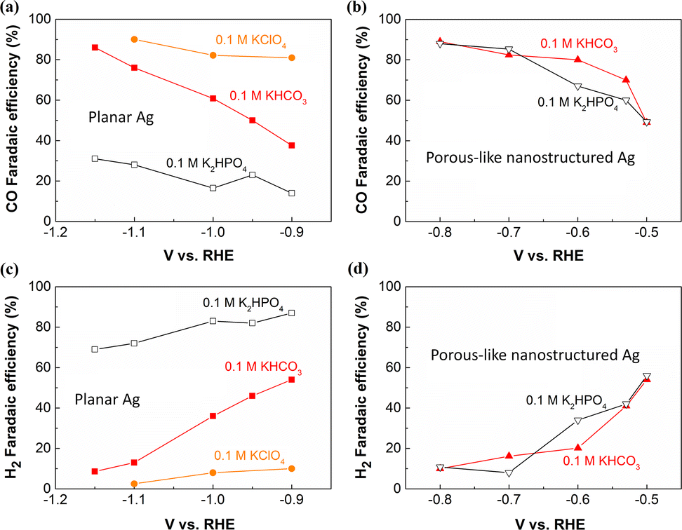 | ||
| Fig. 1 Faradaic efficiencies for CO and H2 on flat Ag foil (a) (c) and porous-like nanostructured Ag (b) (d) at various potentials in 0.1 M K2HPO4, 0.1 M KHCO3 or 0.1 M KClO4 (all electrolytes were saturated with CO2), respectively. This figure has been reproduced from ref. 47 with permission from John Wiley and Sons, copyright 2016. | ||
Understanding and controlling the local pH effects plays an essential role in optimizing the performance of electrochemical CO2 reduction catalysts. However, for getting better mechanistic understanding of the local pH effect on the catalytic selectivity and activity of CO2 reduction, it is highly significant to measure the local pH value over reaction conditions. Great effects have been devoted into the localized pH measurement in the vicinity of the cathode during electrochemical CO2 reduction. In this minireview, we summarize the recent progress of pH measurement methods (Table 2) for quantifying the pH near the cathode of CO2 electroreduction in both H-cells and flow-electrolyzers with gas diffusion electrodes (GDEs), and discuss the pertinent challenges of different techniques. Additionally, the progress of reaction mechanism is also discussed on the basis of local pH determination.
| Techniques | Current density | Reactant | Reactor type | Electrolyte | Ref. |
|---|---|---|---|---|---|
| SEIRAS | CO2 | H-cell | CO2-saturated 0.1 M bicarbonate | 56 and 57 | |
| SEIRAS | 0–120 Am cm−2 | CO2 | H-cell | CO2-saturated 0.2–1 M phosphate buffer | 58 |
| RRDE | 5–15 Am cm−2 | CO2 | H-cell | CO2-saturated 0.1 M bicarbonate | 51 |
| SECM | CO2 | H-cell | Ar or CO2-saturated 0.1 M Li2SO4 | 59 | |
| Raman | 0–120 Am cm−2 | CO2 | Catholyte-flowing GDE electrolyzers | 1 M KOH | 68 |
| Raman | 0–200 Am cm−2 | CO2 | MEA reactors | 3 M KHCO3 | 69 |
| CLSM | 0–100 Am cm−2 | CO2 | Catholyte-flowing GDE electrolyzers | 0.1 M KHCO3 | 39 |
| CO2 capture | 0–250 Am cm−2 | CO | Catholyte-flowing GDE electrolyzers | 1 M KHCO3 | 41 |
2. Local pH measurement in H-type cell
In the past decade, the majority of the CO2 reduction research, including development of high-performance electrocatalysts and the fundamental understanding studies, has been performed in H-type cell reactors that are filled with CO2-saturated electrolytes. Correspondingly, most of the local pH measurement techniques were also based on H-type cell reactors (Fig. 2a), thus we introduce the localized pH measurement methods at low current densities in this section: (i) in situ infrared (IR),56–58 (ii) rotating ring-disk electrode technique (RRDE)51 and (iii) scanning electrochemical microscopy (SECM).59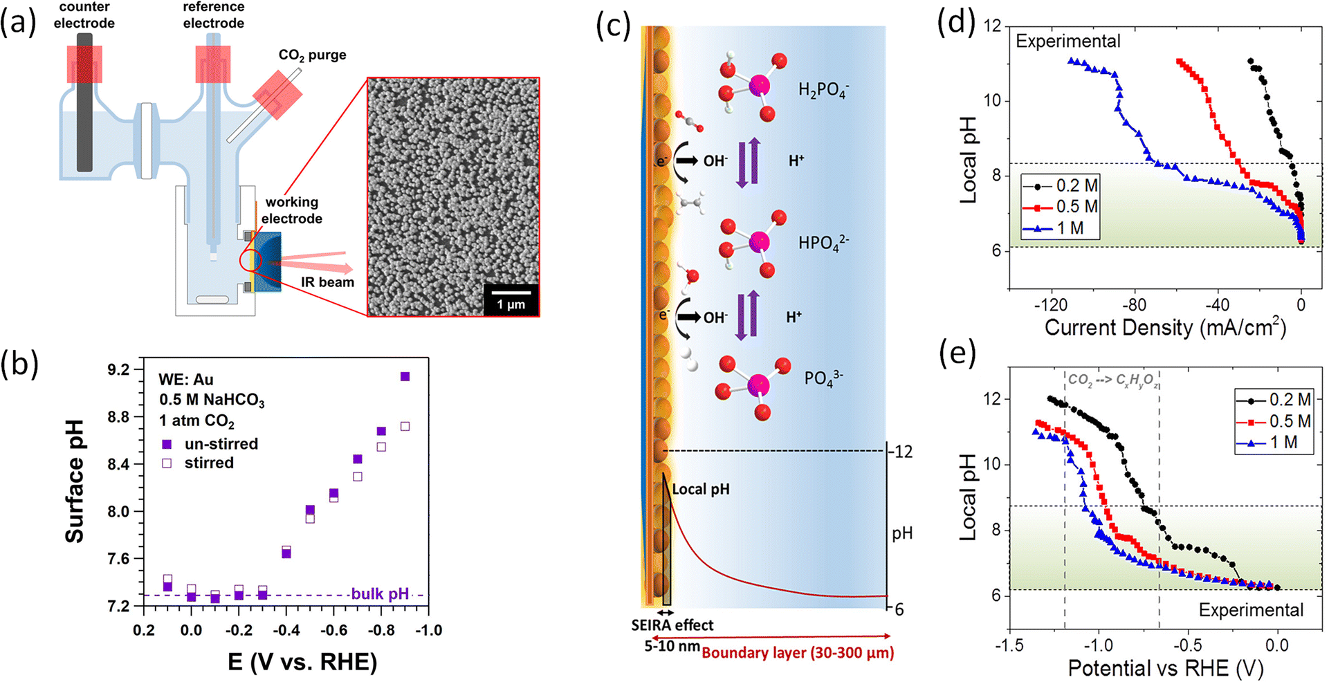 | ||
| Fig. 2 (a) Schematic illustration of H-cell for Raman spectroscopy with Au working electrode. Inset: A SEM image of the Au film on Si. (b) Measured surface pH in CO2-saturated 0.5 M NaHCO3 under stirring (open squares) and without stirring (solid squares), respectively. This figure has been reproduced from ref. 57 with permission from American Chemical Society, copyright 2018. (c) Schematic illustration of buffer reactions, pH gradient, and probed area SEIRA. (d) Experimentally probed and (e) simulated local pH as a function of phosphate buffer concentration and current density. This figure has been reproduced from ref. 58 with permission from American Chemical Society, copyright 2019. | ||
In situ infrared spectroscopy
In situ spectroscopy techniques including IR and Raman spectroscopy can be utilized for probing the pH value locally near the cathode surface via comparing the relative integration of pH-sensitive electrolyte species. For instance, carbonate (CO32−) and bicarbonate (HCO3−) at the electrode/electrolyte interface are commonly treated as pH-sensitive electrolyte species, detected by IR and Raman spectroscopy. The ratio between the integrated intensity of the CO32− and HCO3− bands can provide an approximation of their corresponding concentrations near the cathode surface. The relationship between pH of the electrolyte and the concentration ratio of carbonate/bicarbonate can be expressed by the Henderson–Hasselbalch equation: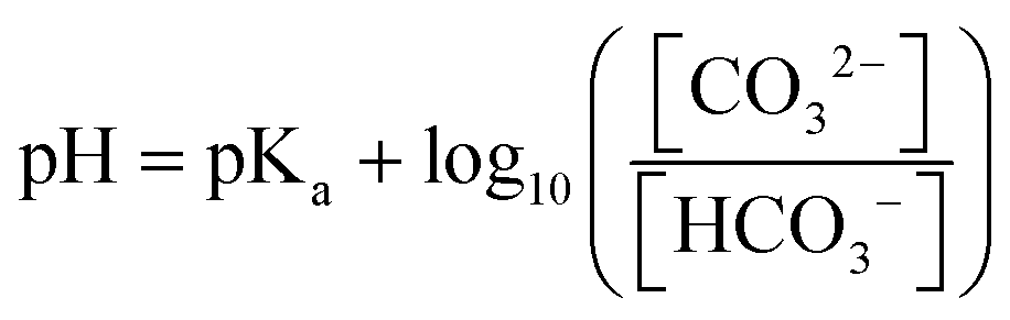 | (1) |
Before the system experiences a significant perturbation via current density, potential, electrolyte flow or even gas flow, the concentrations of CO32− and HCO3− at the interface between electrolyte and cathode surface should be in equilibrium, which means that the spectra obtained by in situ spectroscopy corresponds to equilibrium situation. Thereby, in situ IR or Raman spectroscopy enables to probe the pH locally near the surface of the catalysts via the concentrations of CO32− and HCO3−.
Attenuated total reflectance surface-enhanced infrared absorption spectroscopy (ATR-SEIRAS) can be used to monitor the vibrational bands of carbonate and bicarbonate. By comparing the integrated areas of the vibrational bands with calibration spectra of known pH values of electrolyte to determine pH near the surface. The group of Xu employed ATR-SEIRAS to measure the pH on the surface of Au film cathode at various potentials in CO2-saturated NaHCO3 solutions (as shown in Fig. 2a).57 As expected, the surface pH is higher than the bulk pH, and an increase in surface pH was observed at more negative potentials (Fig. 2b), which is linked to the enhanced production rate of OH− caused by the increased current densities at more negative potentials. In addition, the un-stirred electrolyte experienced a relatively higher surface pH in comparison with that of stirred one at more negative potentials. This finding confirms that, with increasing convection, an increase in mass-transport of ionic species (the transport of bicarbonate towards the surface and the transport of OH− out of the electrode surface) results in the enhanced amount of the neutralization reaction near the catalyst surface.
Using ATR-SEIRAS, early work by Cuesta probed the pH at the gold–electrolyte interface during electrocatalytic CO2 reduction in CO2-saturated 0.1 M MHCO3 solutions (M = Li, Na, K, Cs).56 Authors found that the pH at the interface follows the trend Li+ > Na+ > K+ > Cs+, which is consistent the hypothesis proposed by Singh.25 In that hypothesis, it was proposed that the pKa for cation hydrolysis decreases with larger cation size, thereby larger cation size could maintain the local pH at a relatively low value.25
The phosphate electrolytes are frequently used as high buffer capacity solutions to assess and rule out local pH effects on the catalytic selectivity. The group of Smith utilized SEIRAS to explore the buffer capacity and mass transport to cathode of these electrolytes during CO2 electrolysis in H-cell reactors.58 Depending on the local pH value, the three different phosphate buffer species can be transformed with each other (Fig. 2c). Through monitoring the phosphate buffer species such as H2PO4− and HPO42− near the Cu cathode surface, the pH value can be determined. Specifically, as shown in Fig. 2c, in comparison with the diffuse layer's thickness (30–300 μm), the electric field that causes the surface enhancement effect on SEIRA active thin metal electrodes decays over very short distances (5–10 nm) from the surface, making it possible to track local species concentrations. After assuming that the resulting spectra are linearly correlated with the phosphate species, the pH near the electrode surface was estimated at various current densities or potentials by comparing the ratio of phosphate peaks in the sample spectra to the calibration spectra. For the region of low current density in Fig. 2d, a small difference between local pH and the bulk pH was found at high concentration phosphate buffer. The increase rate of local pH was slower in highly concentrated phosphate buffer upon increasing current densities, (increase in local pH trend follows: 1 M < 0.5 M < 0.2 M). As anticipated, the enhanced concentration of buffer electrolyte considerably influenced the buffering ability. However, authors found that all concentrations of phosphate experienced a rapid breakdown of pH gradient in a narrow potential window (Fig. 2e), which indicates that most of CO2 reduction studies have been carried out in mass transport limited configurations in CO2-saturated solutions.
On the whole, these spectroscopic methods can yield useful information regarding species concentrations near the electrode surface, but the presence of Infrared or Raman active species in solution is necessary for these measurements, and the pH is determined by observing species whose signal depends on the proton concentration. In addition, if the signal of species can be influenced by other local reaction environment factors in addition to proton concentration, the local pH results may be distorted. Thus, attention should also be paid to these factors such as electrolytes that may influence the species when using spectroscopic techniques.
Rotating ring-disc electrode technique
Rotating ring disc electrode provides an in situ pH probe for quantifying the pH locally. RRDE consists of two electrodes, namely, a disc electrode in the center of the system that is surrounded by a thin ring electrode (Fig. 3). Early work by Albery et al. showed the use of the RRDE for measuring proton and hydroxide fluxes via pH-sensitive ring electrodes.60,61 Initially, bismuth, bismuth oxide or Pt ring electrodes were used to quantify the near surface pH from hydrogen evolution and oxygen reduction. Later work electrodeposited iridium oxide on the titanium ring, which was used as the pH sensing material.62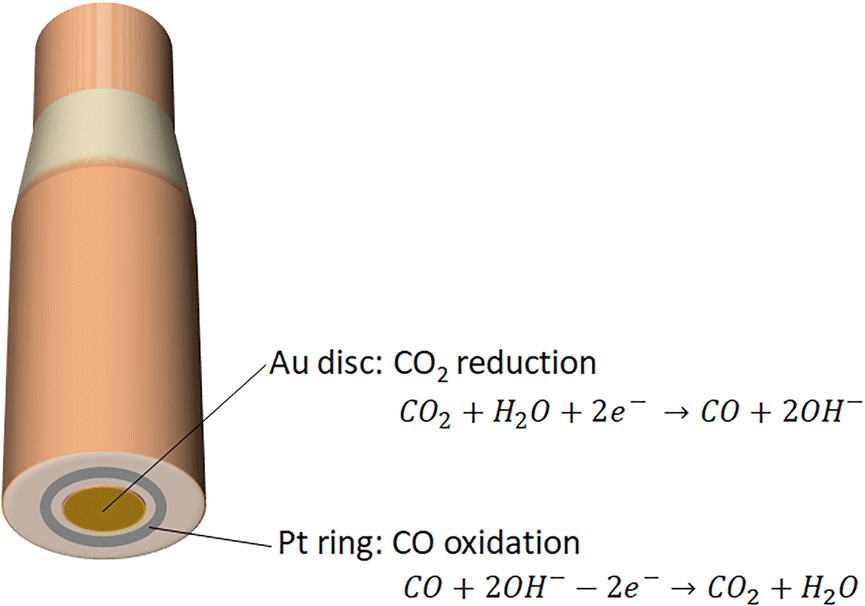 | ||
| Fig. 3 Schematic illustration of rotating ring disc electrode. Electrocatalytic CO2 reduction to CO takes place on Au disc electrode, and subsequently oxidation of CO into CO2 occurs on Pt ring electrode. | ||
Recently, the group of Co demonstrated the utilization of Pt ring for detecting the change of local pH during the course of CO2 reduction in CO2-saturated 0.1 M KHCO3.51 Specifically, the Pt ring is capable of measuring CO that was produced in the CO2 electroreduction on the Au disc electrode, and the shift in the CO oxidation peak potential on the Pt ring electrode delivers local pH change (Fig. 3). In other words, the pH-sensitive peak shift when oxidizing CO on the Pt ring electrode means that CO oxidation serves as the pH probe reaction. The advantage of using the product itself as the pH probe in a RRDE setup is that the process of measurement of surface pH can be carried out without influencing the electrochemical reactions that take place on the disc electrode.
Scanning electrochemical microscopy
Alternatively, local pH can also be measured with high spatial and temporal resolution using scanning electrochemical microscopy (SECM). Generally, iridium oxide or Pt materials are employed as potentiometric pH probes, but these materials could be strongly perturbed via interaction with CO produced in CO2 electroreduction. Thus, it is critical to find a stable pH probe in the reaction environment of CO2 reduction when using this SECM technique for local pH determination over CO2 electrolysis. Monteiro et al. developed a SECM pH probe based on a 4-hydroxylaminothiophenol/4-nitrosothiophenol functionalized Au ultramicroelectrode for quantifying the local pH on a gold substrate in an argon atmosphere and a CO2 atmosphere, respectively.59 Notably, authors discovered the local pH could be overestimated in the presence of the pH tip, owing to that the tip impedes the diffusion of produced species on the electrode surface. Thus, decreasing the radius of the tip insulation layer may be required when using SECM for local pH detection.In this section, all of the aforementioned localized pH probe techniques in H-type reactors show a basic reaction environment near the cathode, which indicates a significantly limited H+ source locally near the cathode. The limited H+ source is unlikely to act as the proton donor in CO2 reduction, thus the proton involved in the electrochemical conversion of CO2 should stem from water, which is consistent with the recent reports.63–65
3. Local pH measurement in GDE-based flow cell
In recent years, CO2 electrolysis technology has advanced from the H-type cell reactors that only work at low current densities (i.e., low reaction rates) to flow electrolyzers with gas diffusion electrodes (GDEs) that allow for achieving commercially-relevant current densities of CO2 reduction. It should be noted CO2 reactant diffuses through the macroporous and microporous layers into the electrolyte, and then a large amount of CO2 can be captured at the cathodic GDE/electrolyte interface via neutralization reaction with OH−, forming carbonate (Fig. 4).43,66 In comparison with H-type cell reactors, this local neutralization reaction between CO2 and OH− not only changes the ionic species and concentration of electrolytes over the course of electrolysis,43,66 but also complicates the local reaction environment value near the cathodic GDE surface in GDE-based flow electrolyzers. For instance, in highly concentrated alkaline catholyte (such as 1 M KOH), the local pH was calculated to be much lower than the bulk pH in catholyte-flowing GDE electrolyzers.67 In contrast, in highly concentrated neutral electrolyte (such as 1 M KHCO3), the local pH was theoretically simulated to be higher in comparison with bulk pH.38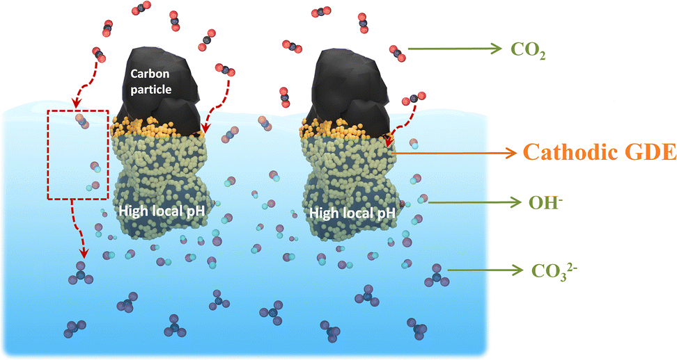 | ||
| Fig. 4 Schematic illustration of CO2 capture at the cathodic GDE/catholyte interface in the form of carbonate via the neutralization reaction with OH− during high-rate CO2 reduction. This Figure has been adapted from ref. 41 with permission from Royal Society of Chemistry, copyright 2022. | ||
To better uncover the complex local reaction environment at high-rate CO2 reduction, it is necessary to probe the local pH near the cathodic GDE surface, where the CO2 reduction takes place, in a flow electrolyzer under reaction conditions. To the best of our knowledge, monitoring the local pH in GDE-based electrolyzers has been demonstrated using three methods to date: (i) Raman spectroscopy,68,69 (ii) fluorescent confocal laser scanning microscopy (CLSM)39 and (iii) comparison of CO2 capture rate.41
Raman spectroscopy for local pH detection near GDE
Basic principle of the application of in situ Raman spectroscopy for quantifying the local pH value during CO2 reduction has been introduced in the previous section. In order to reveal the pH variation from the cathodic GDE surface to the electrolyte bulk, Lu et al. designed a special alkaline-flow CO2 electrolyzer that enables in situ Raman spectroscopy to be carried out under reaction circumstances, as shown in Fig. 5a.68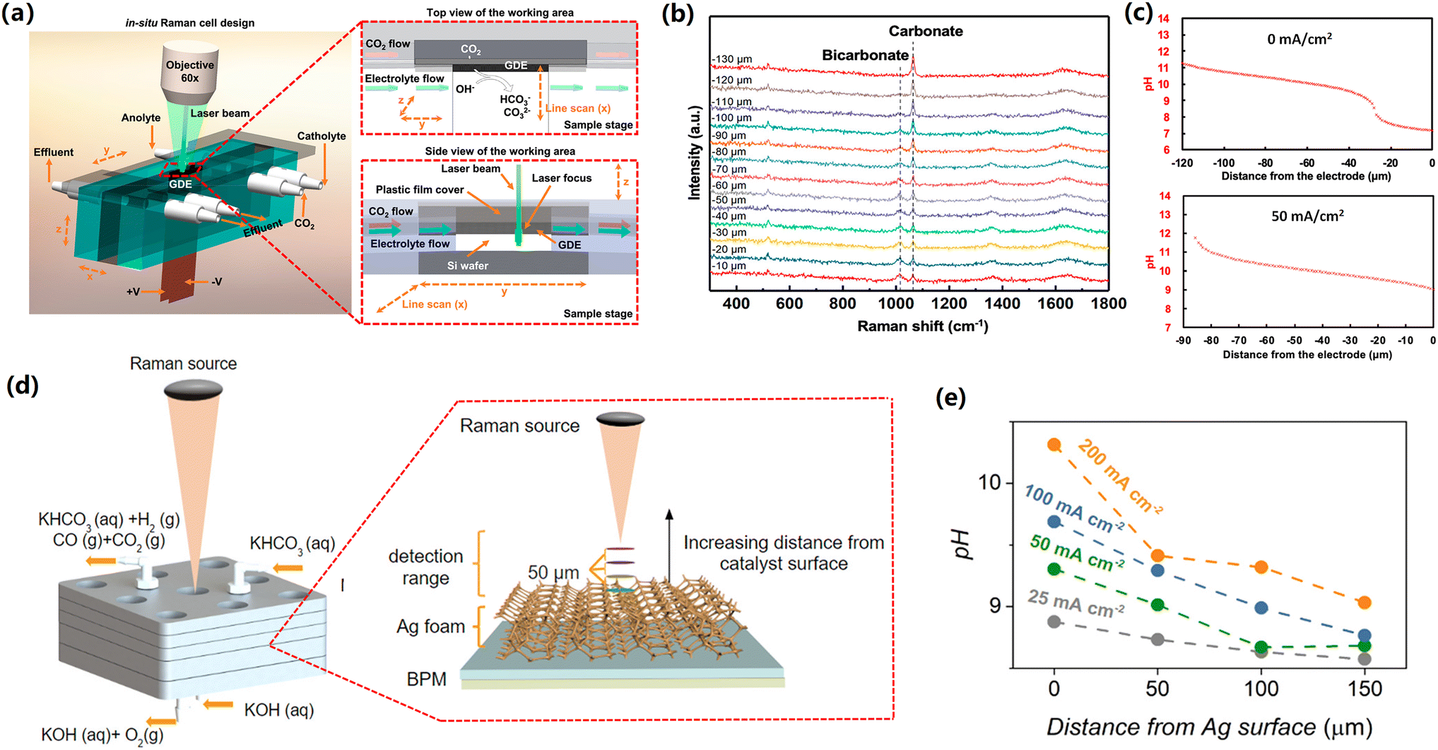 | ||
| Fig. 5 (a) Schematic illustration of special GDE-type flow cell with top and side views of the cathode area. (b) Raman spectra recorded at various distances from the GDE surface at 0 mA cm−2 in 1 M KOH. (c) pH profile as a function of the distance from the GDE surface in 1 M KOH at 0 mA cm−2 (top) and 50 mA cm−2 (bottom). These figures have been reproduced from ref. 68 with permission from American Chemical Society, copyright 2020 (d) Schematic illustration of the zero-gap flow cell. Insert shows how different detection planes were measured using the Raman probe. (e) pH profile as a function of the distance from the cathode surface at various current densities in 3 M KHCO3. These figures have been reproduced from ref. 69 with permission from American Chemical Society, copyright 2020. | ||
Specifically, carbonate and bicarbonate were used as pH-sensitive electrolyte species, owing to that the neutralization reaction of CO2 and OH− near the cathodic GDEs also forms these species and the two pH-sensitive species have distinguishable Raman features.68 In addition, the calibration curves at various standard bicarbonate/carbonate concentrations can be drawn using Raman spectroscopy.
In this catholyte-flowing GDE electrolyzers coupled with in situ confocal Raman spectroscopy, when using 1 M KOH electrolyte at open-circuit conditions, authors found a dominant bicarbonate (low concentration ratio of CO32− to HCO3− in Fig. 5b) near the cathode, which means a nearly neutral local environment near the cathodic GDE surface (within 20 μm from the surface). This observation is due to the neutralization reaction of CO2 and OH− (Fig. 4), which takes place locally near the cathodic GDE surface. Upon further increasing the distance from cathode surface, the concentration ratio of CO32− to HCO3− gradually enhanced (Fig. 5b), indicating an increase in the pH value at the location that is far away from the cathode surface (Fig. 5c). Additionally, when performing CO2 reduction at a current density of 50 mA cm−2, an apparent increase in the pH near the cathodic GDE and a narrow pH gradient layer were observed in comparison with those in zero current (Fig. 5c), which is attributed to the production of OH−via the cathodic reactions near the cathode surface (Table 1).
In previous studies, the use of alkaline electrolyte solutions was reported to be able to significantly lower the overpotential for CO2 reduction compared to neutral ones. The Nernst potential of the aforementioned pH gradient at the cathode/electrolyte interface elucidates the decrease in the overpotential when using alkaline electrolytes as compared to neutral ones.68 In addition, it should be noted that the high local pH is also linked to carbonate formation via neutralization reaction between CO2 and OH−, leading to low carbon utilization for high-rate CO2 electrolysis, particularly in the case of highly concentrated alkaline catholyte.43,66 Recently, acidic CO2 reduction has been proposed to enhance carbon utilization, although acidic CO2 reduction has an enhanced H2 selectivity.70,71
To date, membrane electrode assembly (MEA) configuration represents state-of-the-art performance at commercially-relevant current densities. MEA electrolyser is also referred as zero-gap electrolyzer, in which a membrane is positioned between an anode catalyst and a cathode catalyst. In a MEA configuration with a bipolar membrane using highly concentrated bicarbonate electrolyte (Fig. 5d), the group of Berlinguette showed that an enhancement in the surface pH from 8.5 to 10.3 with increasing the current density from 25 to 200 mA cm−2.69 In addition, the pH experienced a gradual decrease with moving away from the cathode surface and subsequently reached a bulk pH value after getting the boundary of the diffusion layer (Fig. 5e).
It should be noted that MEA configuration can lead to enhanced energy efficiencies via dramatically reducing the ohmic resistance of the whole electrolyzer. However, in the MEA configuration, the direct contact between the catalyst layer and membrane inevitably leads to the effect of the local environment near the surface of the membrane on the catalytic performance. The local environment on the membrane surface is not only determined by the cathodic reactions (production of OH−), but also directly linked to the ionic species transported via the membrane. Currently, the majority of CO2 reduction in the MEA configuration employs anion exchange membranes that normally transfer anionic species (such as OH−, and carbonate) from the cathode side to the anode side. Future work should explore the local reaction environment of the cathode surface in MEA configuration with AEM, which can help to elucidate the reaction mechanisms on the surface of the catalysts.
Fluorescent confocal laser scanning microscopy
While all the aforementioned methods such as SECM, Raman and infrared spectroscopy are capable of spatial resolutions down to the nanoscale level, all these techniques are unable to map the operando pH of a whole macroscopic sample in three dimensions. Recent work by Atwater et al. has demonstrated that fluorescent confocal laser scanning microscopy enables to provide a platform of mapping of the local OH− concentration near the cathodic GDE under reaction conditions in catholyte-flowing GDE electrolyzers at even commercially-relevant current densities.39In this technique, pH-sensitive color fluorescent is added into the electrolyte, and a confocal microscopy can probe the operando local pH near the cathodic GDE surface via monitoring the fluorescence signal under CO2 reduction reaction conditions.72 Authors used a combination of two ratiometric fluorescent dyes which are ratiometric fluorescent photoacid dye 6,8-dihydroxypyrene-1,3-disulfonic acid disodium salt (DHPDS) and 8-aminopyrene-1,3,6-trisulfonic acid trisodium salt (APTS).39 DHPDS is sensitive to pH values from 6 to 10, and APTS can test pH values between 11.2 and 14, thus the two pH-dependent fluorescent ratiometric dyes are capable of measuring a pH range from 6 to 14. The pH maps that are parallel to the cathodic GDE surface in the plane were shown for three different z-positions at various current densities from 0 mA cm−2 and 100 mA cm−2 in the 100 mM KHCO3 electrolyte (Fig. 6).
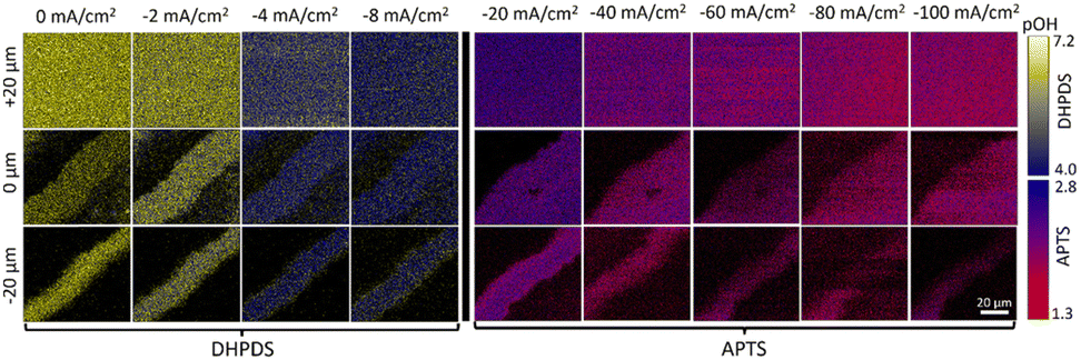 | ||
| Fig. 6 The pH maps in the plane that are parallel to the cathodic GDE surface. This figure has been reproduced from ref. 39 with permission from Royal Society of Chemistry, copyright 2023. | ||
It should be noted that the degradation of the pH-sensitive color fluorescent has been observed at high current densities, which may be attributed to reduction of fluorescent on the cathode surface.39 Thereby, while this CLSM approach has the advantage of reaching time-resolved measurement of local pH for an entire macroscopic sample in three spatial dimensions, the pH-sensitive color fluorescent, which has to be added into the electrolyte for testing pH value, may be involved in the electrochemical reaction, influencing the electrolysis that we want to investigate.
The utilization of CO2 capture rate
A substantial CO2 capture caused by local OH− at the cathodic GDE surface can result in low carbon utilization (waste of CO2 reactant in the form of CO32−).43 However, the capture rate of CO2 in the form of CO32− also reflects the OH− concentration near the cathodic GDE surface. Based on the principle, a simple local pH determination method has been developed recently.41 As expected, a linear enhancement in the CO2 capture rate was found with increasing the current densities (Fig. 7a), which is due to that CO2 capture rate relies on local OH− concentration near cathode surface, and the OH− generation rate is linearly correlated with current densities.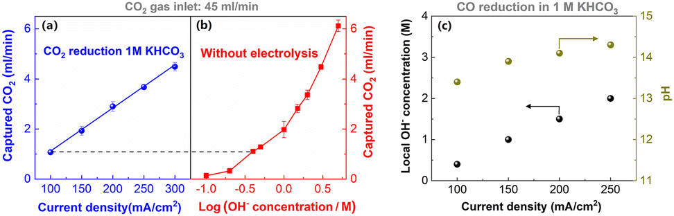 | ||
| Fig. 7 Comparison of CO2 capture rates during CO2 electrolysis at various current densities (a) and for various KOH concentration electrolytes at open-circuit potential (b). (c) The local pH in CO reduction estimated by comparing (c) with (d). This figure has been reproduced from ref. 41 with permission from Royal Society of Chemistry, copyright 2022. | ||
The majority of CO2 capture should occur within the hydrodynamic boundary layer, where reflects the considerable change in local OH− concentration.67 Accordingly, in the same system, the same CO2 capture ability corresponds to the same OH− concentration within the boundary layer. To quantify the current-dependent local pH, the CO2 capture rate as a function of OH− concentration in flow electrolyzers at open-circuit potentials was used as the reference (Fig. 7b). By comparing the CO2 capture rate in CO2 reduction at different current densities (Fig. 7a) with that at different OH− concentration solution at open-circuit potentials (Fig. 7b), an estimate of the local pH in CO reduction was made (Fig. 7c). The local pH in CO reduction gradually enhanced up to ∼14 when the current density increased to 200 mA cm−2 in 1 M KHCO3 (Fig. 7c).
The commonly used spectroscopy is limited to the pH-sensitive electrolyte species such as HCO3− and CO32−, but CO reduction in alkaline electrolytes does not have these kind of pH-sensitive species. Thus, one of main advantages of this simple CO2 capture rate method is that it enables the estimation of local pH for high-rate CO reduction in alkaline electrolytes. Additionally, it does not require any expensive equipment for local pH estimation. However, this technique has the two major drawbacks, (i) it can only estimate the average pH value within the boundary layer, which means that spatial resolutions near the surface cannot be made, and (ii) it is impossible to estimate the local pH during high-rate CO2 reduction.
4. Conclusion and outlook
This minireview summaries the local pH determination techniques for CO2 electroreduction, encompassing (i) in situ infrared spectroscopy, rotating ring-disc electrode technique, and scanning electrochemical microscopy, which were used in H-type cell reactors, and (ii) Raman spectroscopy, fluorescent confocal laser scanning microscopy, and comparsion of CO2 capture rate, which were reported for GDE-type flow electrolzyers. We also discuss the merits and limitations of these different techniques.It should be noted that the majority of the local pH measurement techniques were done in H-type cell reactors. However, the focus of CO2 reduction field has switched to commercially-relevant current densities in the recent few years, and there are still limited studies for local pH determination in GDE-type flow electrolyzers at high current densities, particularly for MEA configuration. The MEA configuration represents state-of-the-art CO2 performance to date, due to its small cell potentials and long-term stability. In this configuration, the catalyst layer and membrane has close contact, thus the local environment near membrane's surface that is close to the cathode side could directly influence the catalytic performance of electrocatalyst. It is essential to understand how a combination of current densities (OH− generation rate) and the ionic species transferred across the membrane influences the local environment and CO2 reduction performance in MEA configuration. Thereby, the future work should focus on the local pH change in the MEA configuration with commonly used ion-exchange membranes.
It should be noted that the significant difference between the local pH and the bulk pH may lead to deviations in the reported potentials on the reversible hydrogen electrode (RHE) scale. In addition, our previous work showed a significant variation in catholyte pH at high-rate CO2 reduction.43 Thus, we suggest using a pH-independent reference such as a standard hydrogen electrode (SHE) to report applied potentials instead of a pH-dependent RHE.
Additionally, although high local pH is generally thought to be able to favor the CO2 electroreduction, it does not mean that CO2 reduction should have the local pH as high as possible. Because high local pH also can reduce the concentration of CO2 reactant via neutralization reaction between CO2 and OH−. How to balance the local pH with CO2 concentration also should be the focus in the future local pH work, which may help us to better understand the reaction mechanism of the local environment effect and further improve the high-rate CO2 reduction performance.
Conflicts of interest
There are no conflicts to declare.Acknowledgements
This work is supported by National Natural Science Foundation of China (22179105) and “Young Talent Support Plan” of Xi'an Jiaotong University (awarded to M. M.). This work was also supported by the Natural Science Program on Basic Research Project of Shaanxi Province (2023-JC-QN-0155).References
- E. W. Lees, B. A. W. Mowbray, F. G. L. Parlane and C. P. Berlinguette, Nat. Rev. Mater., 2021, 7, 55–64 CrossRef.
- D. Wakerley, S. Lamaison, J. Wicks, A. Clemens, J. Feaster, D. Corral, S. A. Jaffer, A. Sarkar, M. Fontecave, E. B. Duoss, S. Baker, E. H. Sargent, T. F. Jaramillo and C. Hahn, Nat. Energy, 2022, 7, 130–143 CrossRef CAS.
- S. Garg, Q. Xu, A. B. Moss, M. Mirolo, W. Deng, I. Chorkendorff, J. Drnec and B. Seger, Energy Environ. Sci., 2023, 16, 1631–1643 RSC.
- Z. W. Seh, J. Kibsgaard, C. F. Dickens, I. Chorkendorff, J. K. Nørskov and T. F. Jaramillo, Science, 2017, 355, eaad4998 CrossRef PubMed.
- D. D. Zhu, J. L. Liu and S. Z. Qiao, Adv. Mater., 2016, 28, 3423–3452 CrossRef CAS PubMed.
- K. Jiang, R. B. Sandberg, A. J. Akey, X. Liu, D. C. Bell, J. K. Nørskov, K. Chan and H. Wang, Nat. Catal., 2018, 1, 111–119 CrossRef CAS.
- M. Ma, K. Djanashvili and W. A. Smith, Angew. Chem., Int. Ed., 2016, 55, 6680–6684 CrossRef CAS PubMed.
- P. De Luna, C. Hahn, D. Higgins, S. A. Jaffer, T. F. Jaramillo and E. H. Sargent, Science, 2019, 364, eaav3506 CrossRef CAS PubMed.
- Z. Li, R. Wu, L. Zhao, P. Li, X. Wei, J. Wang, J. S. Chen and T. Zhang, Nano Res., 2021, 14, 3795–3809 CrossRef CAS.
- R. Shi, J. Guo, X. Zhang, G. I. N. Waterhouse, Z. Han, Y. Zhao, L. Shang, C. Zhou, L. Jiang and T. Zhang, Nat. Commun., 2020, 11, 3028 CrossRef CAS PubMed.
- Y. Hori, I. Takahashi, O. Koga and N. Hoshi, J. Phys. Chem. B, 2002, 106, 15–17 CrossRef CAS.
- K. J. P. Schouten, Z. Qin, E. Pérez Gallent and M. T. M. Koper, J. Am. Chem. Soc., 2012, 134, 9864–9867 CrossRef CAS PubMed.
- D. Zhong, Z. Zhao, Q. Zhao, D. Cheng, B. Liu, G. Zhang, W. Deng, H. Dong, L. Zhang, J. Li, J. Li and J. Gong, Angew. Chem., Int. Ed., 2021, 60, 4879–4885 CrossRef CAS PubMed.
- S. Ma, M. Sadakiyo, M. Heima, R. Luo, R. T. Haasch, J. I. Gold, M. Yamauchi and P. J. A. Kenis, J. Am. Chem. Soc., 2017, 139, 47–50 CrossRef CAS PubMed.
- J. Huang, M. Mensi, E. Oveisi, V. Mantella and R. Buonsanti, J. Am. Chem. Soc., 2019, 141, 2490–2499 CrossRef CAS PubMed.
- J. Gao, H. Zhang, X. Guo, J. Luo, S. M. Zakeeruddin, D. Ren and M. Grätzel, J. Am. Chem. Soc., 2019, 141, 18704–18714 CrossRef CAS PubMed.
- E. L. Clark, C. Hahn, T. F. Jaramillo and A. T. Bell, J. Am. Chem. Soc., 2017, 139, 15848–15857 CrossRef CAS PubMed.
- M. Zhong, K. Tran, Y. Min, C. Wang, Z. Wang, C.-T. Dinh, P. De Luna, Z. Yu, A. S. Rasouli, P. Brodersen, S. Sun, O. Voznyy, C.-S. Tan, M. Askerka, F. Che, M. Liu, A. Seifitokaldani, Y. Pang, S.-C. Lo, A. Ip, Z. Ulissi and E. H. Sargent, Nature, 2020, 581, 178–183 CrossRef CAS PubMed.
- M. Ma, H. A. Hansen, M. Valenti, Z. Wang, A. Cao, M. Dong and W. A. Smith, Nano Energy, 2017, 42, 51–57 CrossRef CAS.
- L. Wan, X. Zhang, J. Cheng, R. Chen, L. Wu, J. Shi and J. Luo, ACS Catal., 2022, 12, 2741–2748 CrossRef CAS.
- W. Luc, X. Fu, J. Shi, J.-J. Lv, M. Jouny, B. H. Ko, Y. Xu, Q. Tu, X. Hu, J. Wu, Q. Yue, Y. Liu, F. Jiao and Y. Kang, Nat. Catal., 2019, 2, 423–430 CrossRef CAS.
- M. Ma, K. Liu, J. Shen, R. Kas and W. A. Smith, ACS Energy Lett., 2018, 3, 1301–1306 CrossRef CAS PubMed.
- J. Zhou, W. Yan, Z. Gan, C. Shu, Z. Zheng, W. Tang, T. Wu, K. Xie and M. Ma, ACS Appl. Energy Mater., 2023, 6, 2954–2961 CrossRef CAS.
- H. Shin, K. U. Hansen and F. Jiao, Nat. Sustain., 2021, 4, 911–919 CrossRef.
- M. R. Singh, Y. Kwon, Y. Lum, J. W. Ager and A. T. Bell, J. Am. Chem. Soc., 2016, 138, 13006–13012 CrossRef CAS PubMed.
- A. Murata and Y. Hori, Bull. Chem. Soc. Jpn., 1991, 64, 123–127 CrossRef CAS.
- A. S. Malkani, J. Anibal and B. Xu, ACS Catal., 2020, 10, 14871–14876 CrossRef CAS.
- S. A. Akhade, I. T. McCrum and M. J. Janik, J. Electrochem. Soc., 2016, 163, F477–F484 CrossRef CAS.
- C. M. Gunathunge, V. J. Ovalle and M. M. Waegele, Phys. Chem. Chem. Phys., 2017, 19, 30166–30172 RSC.
- L. D. Chen, M. Urushihara, K. Chan and J. K. Nørskov, ACS Catal., 2016, 6, 7133–7139 CrossRef CAS.
- J. Resasco, L. D. Chen, E. Clark, C. Tsai, C. Hahn, T. F. Jaramillo, K. Chan and A. T. Bell, J. Am. Chem. Soc., 2017, 139, 11277–11287 CrossRef CAS PubMed.
- S. Ringe, E. L. Clark, J. Resasco, A. Walton, B. Seger, A. T. Bell and K. Chan, Energy Environ. Sci., 2019, 12, 3001–3014 RSC.
- V. J. Ovalle, Y.-S. Hsu, N. Agrawal, M. J. Janik and M. M. Waegele, Nat. Catal., 2022, 5, 624–632 CrossRef CAS.
- C. Kim, J. C. Bui, X. Luo, J. K. Cooper, A. Kusoglu, A. Z. Weber and A. T. Bell, Nat. Energy, 2021, 6, 1026–1034 CrossRef CAS.
- J. C. Bui, C. Kim, A. J. King, O. Romiluyi, A. Kusoglu, A. Z. Weber and A. T. Bell, Acc. Chem. Res., 2022, 55, 484–494 CrossRef CAS PubMed.
- A. Goyal and M. T. M. Koper, J. Chem. Phys., 2021, 155, 134705 CrossRef CAS PubMed.
- R. Kas, R. Kortlever, H. Yılmaz, M. T. M. Koper and G. Mul, ChemElectroChem, 2015, 2, 354–358 CrossRef CAS.
- T. Burdyny and W. A. Smith, Energy Environ. Sci., 2019, 12, 1442–1453 RSC.
- A. Böhme, J. C. Bui, A. Q. Fenwick, R. Bhide, C. N. Feltenberger, A. J. Welch, A. J. King, A. T. Bell, A. Z. Weber, S. Ardo and H. A. Atwater, Energy Environ. Sci., 2023, 16, 1783–1795 RSC.
- N. Gupta, M. Gattrell and B. MacDougall, J. Appl. Electrochem., 2005, 36, 161–172 CrossRef.
- M. Ma, W. Deng, A. Xu, D. Hochfilzer, Y. Qiao, K. Chan, I. Chorkendorff and B. Seger, Energy Environ. Sci., 2022, 15, 2470–2478 RSC.
- S. Nitopi, E. Bertheussen, S. B. Scott, X. Liu, A. K. Engstfeld, S. Horch, B. Seger, I. E. L. Stephens, K. Chan, C. Hahn, J. K. Nørskov, T. F. Jaramillo and I. Chorkendorff, Chem. Rev., 2019, 119, 7610–7672 CrossRef CAS PubMed.
- M. Ma, E. L. Clark, K. T. Therkildsen, S. Dalsgaard, I. Chorkendorff and B. Seger, Energy Environ. Sci., 2020, 13, 977–985 RSC.
- Y. Hori, A. Murata and R. Takahashi, J. Chem. Soc., Faraday Trans. 1, 1989, 85, 2309 RSC.
- Y. Hori, in Modern Aspects of Electrochemistry, ed., C. G. Vayenas, R. E. White and M. E. Gamboa-Aldeco, Springer, New York, 2008, vol. 42, pp. 89–189 Search PubMed.
- R. Kas, R. Kortlever, A. Milbrat, M. T. M. Koper, G. Mul and J. Baltrusaitis, Phys. Chem. Chem. Phys., 2014, 16, 12194 RSC.
- M. Ma, B. J. Trześniewski, J. Xie and W. A. Smith, Angew. Chem., Int. Ed., 2016, 55, 9748–9752 CrossRef CAS PubMed.
- P. De Luna, R. Quintero-Bermudez, C.-T. Dinh, M. B. Ross, O. S. Bushuyev, P. Todorović, T. Regier, S. O. Kelley, P. Yang and E. H. Sargent, Nat. Catal., 2018, 1, 103–110 CrossRef CAS.
- W. Luo, J. Zhang, M. Li and A. Züttel, ACS Catal., 2019, 9, 3783–3791 CrossRef CAS.
- Y. Y. Birdja, E. Pérez-Gallent, M. C. Figueiredo, A. J. Göttle, F. Calle-Vallejo and M. T. M. Koper, Nat. Energy, 2019, 4, 732–745 CrossRef CAS.
- F. Zhang and A. C. Co, Angew. Chem., Int. Ed., 2020, 59, 1674–1681 CrossRef CAS PubMed.
- Y. Zhao, L. Hao, A. Ozden, S. Liu, R. K. Miao, P. Ou, T. Alkayyali, S. Zhang, J. Ning, Y. Liang, Y. Xu, M. Fan, Y. Chen, J. E. Huang, K. Xie, J. Zhang, C. P. O'Brien, F. Li, E. H. Sargent and D. Sinton, Nat. Synth., 2023, 2, 403–412 CrossRef.
- M. Ma, K. Djanashvili and W. A. Smith, Phys. Chem. Chem. Phys., 2015, 17, 20861–20867 RSC.
- Y. Chen, C. W. Li and M. W. Kanan, J. Am. Chem. Soc., 2012, 134, 19969–19972 CrossRef CAS PubMed.
- Q. Lu and F. Jiao, Nano Energy, 2016, 29, 439–456 CrossRef CAS.
- O. Ayemoba and A. Cuesta, ACS Appl. Mater. Interfaces, 2017, 9, 27377–27382 CrossRef CAS PubMed.
- M. Dunwell, X. Yang, B. P. Setzler, J. Anibal, Y. Yan and B. Xu, ACS Catal., 2018, 8, 3999–4008 CrossRef CAS.
- K. Yang, R. Kas and W. A. Smith, J. Am. Chem. Soc., 2019, 141, 15891–15900 CrossRef CAS PubMed.
- M. C. O. Monteiro, A. Mirabal, L. Jacobse, K. Doblhoff-Dier, S. C. Barton and M. T. M. Koper, JACS Au, 2021, 1, 1915–1924 CrossRef CAS PubMed.
- W. J. Albery and E. J. Calvo, J. Chem. Soc., Faraday Trans. 1, 1983, 79, 2583 RSC.
- W. J. Albery and A. R. Mount, J. Chem. Soc., Faraday Trans. 1, 1989, 85, 1181 RSC.
- P. Steegstra and E. Ahlberg, J. Electroanal. Chem., 2012, 685, 1–7 CrossRef CAS.
- M. C. O. Monteiro, F. Dattila, B. Hagedoorn, R. García-Muelas, N. López and M. T. M. Koper, Nat. Catal., 2021, 4, 654–662 CrossRef CAS.
- W. Deng, P. Zhang, B. Seger and J. Gong, Nat. Commun., 2022, 13, 803 CrossRef CAS PubMed.
- J. Gu, S. Liu, W. Ni, W. Ren, S. Haussener and X. Hu, Nat. Catal., 2022, 5, 268–276 CrossRef CAS.
- M. Ma, S. Kim, I. Chorkendorff and B. Seger, Chem. Sci., 2020, 11, 8854–8861 RSC.
- M. Jouny, W. Luc and F. Jiao, Nat. Catal., 2018, 1, 748–755 CrossRef CAS.
- X. Lu, C. Zhu, Z. Wu, J. Xuan, J. S. Francisco and H. Wang, J. Am. Chem. Soc., 2020, 142, 15438–15444 CrossRef CAS PubMed.
- Z. Zhang, L. Melo, R. P. Jansonius, F. Habibzadeh, E. R. Grant and C. P. Berlinguette, ACS Energy Lett., 2020, 5, 3101–3107 CrossRef CAS.
- J. E. Huang, F. Li, A. Ozden, A. Sedighian Rasouli, F. P. García de Arquer, S. Liu, S. Zhang, M. Luo, X. Wang, Y. Lum, Y. Xu, K. Bertens, R. K. Miao, C.-T. Dinh, D. Sinton and E. H. Sargent, Science, 2021, 372, 1074–1078 CrossRef CAS PubMed.
- B. Pan, J. Fan, J. Zhang, Y. Luo, C. Shen, C. Wang, Y. Wang and Y. Li, ACS Energy Lett., 2022, 7, 4224–4231 CrossRef CAS.
- A. J. Welch, A. Q. Fenwick, A. Böhme, H.-Y. Chen, I. Sullivan, X. Li, J. S. DuChene, C. Xiang and H. A. Atwater, J. Phys. Chem. C, 2021, 125, 20896–20904 CrossRef CAS.
| This journal is © The Royal Society of Chemistry 2024 |