 Open Access Article
Recent progress in nickel single-atom catalysts for the electroreduction of CO2 to CO
Ziyan
Yang
a,
Rongzhen
Chen
a,
Ling
Zhang
a,
Yuhang
Li
 *a and
Chunzhong
Li
 *b
*b
aKey Laboratory for Ultrafine Materials of Ministry of Education, Shanghai Engineering Research Center of Hierarchical Nanomaterials, School of Materials Science and Engineering, East China University of Science and Technology, Shanghai 200237, People's Republic of China. E-mail: yuhangli@ecust.edu.cn
bKey Laboratory for Ultrafine Materials of Ministry of Education, Shanghai Engineering Research Center of Hierarchical Nanomaterials, School of Chemical Engineering, East China University of Science and Technology, Shanghai 200237, People's Republic of China
First published on 9th January 2024
Abstract
The electrocatalytic reduction of carbon dioxide (CO2) is considered an effective strategy for mitigating the energy crisis and the greenhouse effect. Nickel is widely used in single-atom catalysts (SACs) owing to its special electronic structure. In this minireview, the basic principles of Ni SACs in the electrocatalytic reduction of CO2 to CO are first described. Subsequently, Ni SACs are divided into three categories depending on different strategies used to improve properties. The synthesis, morphology, performance and theoretical calculations of the catalysts are also described. Finally, an overview of the existing challenges and perspectives of Ni SACs for CO2 reduction is presented.
Keywords: CO2 reduction; Electrocatalysis; Nickel single-atom catalysts.
1 Introduction
Since the industrial revolution of the 18th century, fossil fuel consumption has been rising. Consequently, the emission of CO2 has also increased drastically. This has led to a number of environmental issues that can no longer be ignored, especially the energy crisis and the greenhouse effect.1 Some studies have proposed that the atmospheric CO2 concentration could reach 570 ppm by 2100, which raises awareness of the importance of closing the carbon cycle. The use of clean energy to drive the CO2 reduction reaction (CO2RR) to convert CO2 into value-added fuels and chemicals is widely considered one of the most promising strategies.2 For instance, electrocatalysis, photocatalysis and thermocatalysis are the most popular routes nowadays.3 Electrochemical CO2 reduction (ECR) aims to transfer CO2 into chemicals and fuels by generating electricity from renewable energy sources, such as wind, solar and tidal energy. ECR has attracted considerable attention owing to its following advantages: 1) easier access to products such as methanol and C2+ compared to thermocatalysis, especially at a low pressure; 2) lower temperature and pressure requirements for the reaction process, resulting in a gentler reaction environment; 3) modular reaction systems have more potential to be scaled up for industrial applications; 4) more environmentally friendly using renewable energy resources, such as solar and wind, to drive CO2RR.4,5 However, ECR still faces challenges with product separation, unavoidable competitive hydrogen evolution reaction (HER), sluggish kinetics, and inert thermodynamics.ECR produces an extensive variety of products, the most typical of which are CO, CH4, HCOOH, CH3OH, CH3CH2OH, HCHO, and C2H4. Note that CO2RR is unavoidably accompanied by HER, and therefore, the products always contain hydrogen. Up to now, metal oxides, metal alloys, metal nanoparticles and composite materials have undergone broad investigation.6–12 In addition, the electronic structures of catalysts have a considerable influence on the contribution of products.13,14 SACs have prompted high research interest owing to their maximum atom-utilization efficiency, adjustable coordination structures and tunable catalytic properties.15,16 Hence, the application of SACs in CO2RR could effectively control the distribution of products and alleviate the cost of product separation.
Among the multiple reduction products, CO is regarded as having the highest market value as it is a crucial feedstock for the Fischer–Tropsch process, which can synthesize high-value long-chain hydrocarbons.17 Moreover, because CO is a gaseous product, the complicated and expensive post-treatment procedure of gas–liquid separation is avoided. In recent years, transition metals (Fe, Co and Ni) with unique electronic structures and abundant sources have attracted a lot of attention. Although these metals are designed to be dispersed at the atomic level, the catalysts show impressively high selectivity for CO in ECR. In particular, Ni SACs always exhibit superior performance. However, the reaction mechanism remains unclear. In some studies, DFT calculations based on crystal-field theory indicate that the d-orbital electronic configurations of central metals are significant to the selectivity and activity of CO2RR.18,19 The central Ni atoms of the Ni SACs are more likely to form the vacant outermost d-orbital that facilitates electron transfer between the C atom of CO2 and the Ni atom. Consequently, CO2 molecules adsorbed on the catalyst surface can be efficiently activated. Ni SACs can also minimize the reaction potential of CO2–CO conversion, which enhances the selectivity towards CO.
This review begins by introducing the reaction pathway of CO2RR to generate CO. Then, it describes the current methods and mechanisms for identifying the active sites of Ni SACs. Subsequently, the recently developed nickel-based nitrogen-doped carbon single-atom catalytic materials are divided into the following three categories based on the different strategies used to boost catalytic performance: 1) different structures of supports, 2) coordination structure regulation, and 3) surface modification. Finally, we summarize the existing challenges of Ni SACs and provide an outlook on future development.
2 Fundamental mechanisms
2.1 Reaction pathway
Experimental research and theoretical simulation show that the whole CO2RR progress can be divided into three parts: 1) CO2 molecules adsorbed on the catalyst surface; 2) multiple proton-coupled electron transfer (PCET) processes occur between the catalyst and the absorbed CO2 to activate linear CO2 molecules and form key intermediates; and 3) product desorption from the surface of the catalysts. The PCET process is an essential part of the entire reaction that determines the type of target products. However, some studies have indicated that the activation of CO2 is associated only with electron transfer and without proton coupled.16 Thus far, the experimental products of CO2RR mainly include CO, HCOOH, CH3OH, CH4, C2H4 and C2H5OH. The corresponding half reactions and equilibrium potentials (versus reversible hydrogen electrode (RHE)) are listed as follows (Table 1):20| Reaction | E 0 (V vs. RHE) | (Product) name |
|---|---|---|
| CO2 + 2H+ + 2e− → CO + H2O | −0.10 | Carbon monoxide |
| CO2 + 2H+ + 2e− → HCOOH | −0.12 | Formic acid |
| CO2 + 6H+ + 6e− → CH3OH + H2O | 0.03 | Methanol, MeOH |
| CO2 + 8H+ + 8e− → CH4 + 2H2O | 0.17 | Methane |
| 2CO2 + 12H+ + 12e− → C2H4 + 4H2O | 0.08 | Ethylene |
| 2CO2 + 12H+ + 12e− → C2H5OH + 3H2O | 0.09 | Ethanol, EtOH |
CO2RR is normally accompanied by inert thermodynamics and sluggish kinetics, which is associated with the high dissociation energy of the C![[double bond, length as m-dash]](https://www.rsc.org/images/entities/char_e001.gif) O bond in CO2 and the multiple PCET steps.21 Therefore, electrocatalysts are essential for CO2RR processes, which are the most promising to accelerate the reaction rates, lower the overpotential, and even improve the selectivity. Among the various electrocatalysts, such as metal–organic complexes, metal alloys, and metal oxides, single-atom catalysts display superior catalytic performance. Numerous experimental results have shown that the main product of CO2RR on SACs is CO. The mechanism of the electrochemical conversion of CO2 to CO at single-atom sites typically involves the following steps:
O bond in CO2 and the multiple PCET steps.21 Therefore, electrocatalysts are essential for CO2RR processes, which are the most promising to accelerate the reaction rates, lower the overpotential, and even improve the selectivity. Among the various electrocatalysts, such as metal–organic complexes, metal alloys, and metal oxides, single-atom catalysts display superior catalytic performance. Numerous experimental results have shown that the main product of CO2RR on SACs is CO. The mechanism of the electrochemical conversion of CO2 to CO at single-atom sites typically involves the following steps:
| CO2 + * → *CO2 | (1) |
| *CO2 + H+ + e− → *COOH | (2a) |
| *CO2 + e− → *CO2˙− | (2b) |
| *CO2˙− + H+ → *COOH | (2c) |
| *COOH + H+ + e− → *CO + H2O | (3) |
| *CO → CO + *, | (4) |
First, the C atom of the CO2 molecule is absorbed on the active site of the SACs (eqn (1)). In the next process, *COOH is widely believed to be the key intermediate for the reduction of CO2 to CO. However, two paths possibly form *COOH. One is through a single PCET process (eqn (2a)), and the other is through a single electron transfer to convert *CO2˙− intermediate (eqn (2b)), which then quickly gains a proton to form *COOH (eqn (2c)).22,23 But if the binding between the C atom and the active site is not strong enough, free CO2˙− intermediate potential forms HCOOH through an out-sphere reaction pathway.24 Then, the *COOH intermediate undergoes proton electron transfer and subsequently forms the *CO intermediate (eqn (3)). Finally, *CO desorbs from the active sites and indicates the accomplishment of reducing CO2 to CO (eqn (4)). The whole corresponding process is regarded as a proton-decoupled electron transfer mechanism (PDET).
2.2 Active sites
In recent studies, SACs have shown great advantages in enhancing activity, selectivity, and stability. Many experimental studies have demonstrated that SACs combine the properties of both homogeneous and heterogeneous electrocatalysts.25 It is generally agreed that SACs downsize the active sites to an atomic scale and therefore obtain extraordinary electronic structure, powerful metal–support interactions, low-coordinated metal atoms, and maximum atom utilization simultaneously. However, it remains a great challenge to investigate the source of these excellent properties and reveal the mechanism that is essential for precisely regulating the performance of CO2RR.Among single-atom catalysts, metal and nitrogen doped carbon (M–N–C) catalysts have been widely explored. The single atom sites with nitrogen coordinated (M–Nx) in M–N–Cs are assumed to be significantly different from corresponding metal counterparts in molecular and electronic structures, enabling them to be more active in key catalytic reactions.26 Early in the study, the Fe–N–C system shows excellent performance for oxygen reduction reaction (ORR) in both acidic and alkaline media. The atomically dispersed Fe–Nx sites have been convincingly proved to be active for ORR through several physical characterization techniques and catalytic tests, with Fe–N4 being a particularly potential structure of active sites.27–29 As Ni–N–C catalysts display a significant promise in CO2RR, more and more researchers have been studying whether Ni–Nx is the source of its activity.
The first challenge is to prove the single atomic site and characterize the coordinated structure of metal atoms. Koshy et al.30 combined single-atom electron energy loss spectroscopy (EELS), annular dark-field scanning transmission electron microscopy (ADF-STEM), and time-of-flight secondary ion mass spectrometry (ToF-SIMS) to show conclusive proof of the presence of NiNx. They prepared three NiPACN samples with different Ni loadings: NiPACN-0.5 wt% Ni, NiPACN-3.5 wt%, and PR-NiPACN-3.5 wt% (postreaction high Ni loading NiPACN sample). The ADF-STEM images showed that Ni atoms were dispersed atomically and even remained after exposure to electrochemical CO2RR. Then, atomic resolution EELS is applied to NiPACN-3.5 wt%, which shows the coexistence of N K-edge and Ni L-edge signals on single Ni atoms and affords microscopic evidence for NiNx coordination. Finally, the results of the ToF-SIMS showed the presence of NiNxCy fragments, thereby directly confirming the coordination of the single Ni atom with nitrogen. With the comparison of Ni phthalocyanine, the active sites are supposed to be NiN4.
The second challenge is to correlate the NiNx sites with electrochemical activity. Koshy and his co-workers31 have investigated this through hard and soft X-ray spectroscopy. The NiNx sites are most likely to be the active sites for reducing CO2 into CO after comparing with Ni aggregates. Then, three NiPACN samples with different Ni loadings of 0 wt%, 0.5 wt% and 3.4 wt% were prepared. Moreover, as the Ni loading increases, the partial current density of CO (jCO) also increases until the STEM-HAADF and XRD have observed the appearance of Ni nanoparticles (NPs) in the catalyst. The hard and soft X-ray spectroscopic results reveal that pyrrolic-coordinated Ni atoms are active sites that strongly resemble the active sites of molecular Ni porphyrin catalysts.
The highly heterogeneous nature of Ni–N–C leads to difficulty in characterization by nonspatially resolved methods. Zhang et al.32 have found that scanning transmission X-ray microscopy (STXM) is an effective tool for exploring this catalyst. The results also reveal that NiNx is the source of high activity. Up to now, most studies have identified active sites by comparing different metal loading samples with ex situ characterization methods. It remains a big challenge to develop in situ and operando technologies to directly observe the involvement of NiNx sites in the reaction and understand the mechanisms of the CO2RR.33
3 Classification of Ni SACs
In recent years, Ni SACs have been extensively researched because of the high selectivity of CO and the inhibition of competing hydrogen evolution reactions (HER).34Table 2 displays some of the reported Ni SACs for the conversion of CO2 to CO and superior performance. As shown in Fig. 1, based on different strategies to enhance performance, Ni SACs can be classified into the following three kinds: (1) different structures of supports, (2) coordination structure regulation, and (3) surface modification.| Electrocatalysts | Reactors | Electrolyte | FECO max (%) | Potential (vs. RHE) | Total current density (mA cm−2) | TOF (h−1) | Ref. |
|---|---|---|---|---|---|---|---|
| Ni–N–C | H cell | 0.5 M KHCO3 | 97 | −0.65 | 15 | 3200 | 18 |
| Ni-N-Gr | A separated electrochemical cell | 0.1 M KHCO3 | ∼95 | −0.7 | >0.2 | 2700 | 35 |
| Ni-NG | Membrane electrode assembly (MEA) | 0.1 M KHCO3 | 97 | 2.78 V (cell voltage) | 50 | 210![[thin space (1/6-em)]](https://www.rsc.org/images/entities/char_2009.gif) 000 000 |
36 |
| Ni-NG-acid | H cell | 0.5 M KHCO3 | 97 | −0.9 | 27.2 | 2278 | 37 |
| Ni@NCNTs | H cell | 0.5 M KHCO3 | 99.1 | −0.8 | 8.08 | — | 38 |
| NiSA-N-CNTs | A gas-tight electrochemical cell | 0.5 M KHCO3 | 91.3 | −0.7 | 25.7 | 90![[thin space (1/6-em)]](https://www.rsc.org/images/entities/char_2009.gif) 000 000 |
39 |
| A-Ni@CMK | Flow cell | 1 M KOH | 99.5 | −0.6 | 248 | — | 40 |
| Ni-NC(AHP) | H cell | 0.5 M KHCO3 | ∼100 | −0.9 | 14.5 | 7500 | 41 |
| Ni-NC(HPU) | H cell | 0.5 M KHCO3 | 91 | −0.8 | 27.1 | 3250 | 42 |
| NiSA-NGA-900 | H cell | 0.5 M KHCO3 | 90.2 | −0.8 | 6.5 | — | 43 |
| Ni-HPNCFs | H cell | 0.5 M KHCO3 | 97 | −1.0 | 59.6 | 24![[thin space (1/6-em)]](https://www.rsc.org/images/entities/char_2009.gif) 900 900 |
44 |
| Ni–N–C-900 | Flow cell | 1 M KOH | 98 | −0.96 | 400 | >5500 | 45 |
| SA-NiNG-NV | H cell | 0.5 M KHCO3 | 96.4 | −0.7 | 12.5 | 1000 | 46 |
| NiNG-S | H cell | 0.5 M KHCO3 | 97 | −0.8 | 22.5 | 2000 | 47 |
| Ni–N4–O/C | H cell | 0.5 M KHCO3 | 99.2 | −0.9 | 23.2 | 11![[thin space (1/6-em)]](https://www.rsc.org/images/entities/char_2009.gif) 187 187 |
48 |
| NiSA(0.3)-N-PGC | H cell | 0.1 M KHCO3 | 97.2 | −0.76 | 25 | 7000 | 49 |
| Ni/Fe–N–C | H cell | 0.5 M KHCO3 | 98 | −0.7 | 9.5 | 3000 | 50 |
| Ni/Cu–N–C | H cell | 0.5 M KHCO3 | 97.7 | −0.7 | 14.0 | 7000 | 51 |
| Ni-N3-NCNFs | Flow cell | 1 M KHCO3 | 96 | −0.72 | 150 | — | 52 |
| Ni@C3N4-CN | H cell | 0.5 M KHCO3 | ∼99 | −0.8 | 4 | 2000 | 53 |
| Ni0.037-NG-H | H cell | 0.5 M KHCO3 | 97.3 | −0.8 | 15.4 | — | 54 |
| Ni@N-C | Flow cell | 1 M KOH | 97 | −1.1 | 244 | — | 55 |
| Ni(NC) | Flow cell | 1 M KOH | 99 | −1.82 | 160 | — | 56 |
| NiNP2@NiSA2-NG | Flow cell | 1 M KOH | 98 | −0.58 | 200 | — | 57 |
| NiO/Ni–N–C-800 | H cell | 0.1 M KHCO3 | 96.5 | −1.1 | 16.5 | 9200 | 58 |
 | ||
| Fig. 1 Schematic representation of the classification of Ni SACs according to different regulatory strategies. | ||
3.1 Different structures of supports
The traditional structure of Ni SACs is that the central nickel atom is uniformly distributed on supports and is in coordination with four nitrogen atoms (Ni–N4). Carbon supports allow fast electron transport and have advantages in terms of high electrical conductivity. In addition, these supports show low activity toward the competing HER.59 With all these unique properties, carbon frameworks are extensively exploited for bonding single atom sites. The most popular types are carbon nanotubes, graphene, and carbon black.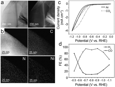 | ||
| Fig. 2 (a) Representative TEM image of Ni-N-Gr (left) and corresponding high-angle annular dark-field scanning image (right). (b) High-resolution TEM image of Ni-N-Gr and corresponding EDX maps of C, N, and Ni. (c) Cyclic voltammograms of Ni-N-Gr catalyst in CO2-saturated 0.1 M KHCO3 and Ar-saturated 0.1 M KH2PO4/K2HPO4 (pH = 6.8) at 10 mV s−1. (d) FEs for the reduction products generated by Ni-N-Gr catalyst.35 Reprinted with permission from Wiley-VCH, copyright 2016. | ||
Graphene, as a two-dimensional layered material, has various chemical coordination environments and well-defined atomic structures that modulate the electronic properties of confined intra-layer guest atoms. Thus, if individual atoms are controllably confined in graphene vacancies, the nickel electronic structure can be efficiently tuned to achieve selective CO2–CO conversion. Jiang et al.36 scattered single Ni atoms into a layered graphene nanosheet (NS), denoted as Ni-NG. The atomic dispersion and atomic coordination of Ni have been confirmed by operando X-ray absorption spectroscopy (XAS) and aberration-corrected scanning transmission electron microscopy (STEM). The XANES and EXAFS of Ni and N in Ni-NG are only slightly different from those of Ni-Pc, suggesting that Ni–N4 is the dominant structure. The catalytic activity for CO2RR was tested by drop-casting onto a mirror-polished glassy carbon electrode and then set into a standard three-electrode H-cell configuration with an electrolyte of CO2-saturated 0.5 M KHCO3. The onset potential is −0.31 V; the FE of CO rises quickly to 83% at −0.60 V, and it is maintained above 90% until −0.87 V. After increasing the catalyst loading to 1 mg cm−2 by changing the electrode to carbon fiber paper, the current density increases drastically. At a 620 mV overpotential, CO FE reached a maximum of about 95% at a current density of around 11 mA cm−2. The current density did not increase linearly as the catalyst loading increases probably owing to the overlapping graphene layers on the carbon fiber paper. In addition, after over 20 hours of continuous measurement, Ni-NG maintains a stable current density with a CO selectivity of about 90%, which represents impressive electrocatalytic durability. Wang et al.37 also found that the annealing temperature during the synthesis of the catalyst is essential to tuning both the properties of the graphene layer and the distribution of the single nickel sites. They synthesized the catalysts at four temperatures (700, 800, 900, and 1100 °C) and then processed them in 0.5 M H2SO4 for acid treatment. The products are denoted as Ni-NG-X-acid (where X represents the temperature). Images of TEM suggest that higher reaction temperatures are conducive to C–N cleavages, leading to more defects in graphene layers for Ni NPs to transport and generate larger particles without fully enveloping the graphene shell. Hence, after annealing and acid treatment, the catalyst embeds more active Ni sites in hollow graphene shells. In combination with XRD patterns, Raman spectra, and TEM, all the outstanding performance is attributed to the greater specific surface area owing to a higher degree of graphitization at higher temperatures, allowing for more exposure of the Ni active sites. Electrochemical performance tests indicate that 1000 °C is the optimum annealing temperature. Within a wide potential window of −0.7 V to −1.2 V, the CO FE is above 90%. At −1.2 V, jCO achieves 27.2 mA cm−2.
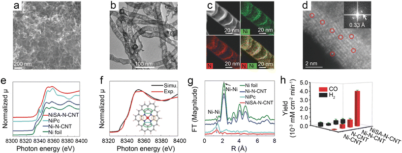 | ||
| Fig. 3 (a–d) Characterization of NiSA-N-CNTs, (a) scanning electron microscopy (SEM) image; (b) transmission electron microscopy (TEM) image; (c) STEM-EDS mapping; (d) ADF image showing the Ni single atoms located on the walls of a CNT (the red circles show typical Ni atoms embedded in the carbon plane of walls. The insert is the Fourier transform of (d)); (e–g) chemical environment of NiSA-N-CNTs as probed via X-ray absorption spectroscopy; (e) Ni K-edge spectra of the EXAFS spectrum; (f) comparison of a simulated XANES spectrum of the inserted Ni-core structure with experimental results; (g) Fourier transform of the EXAFS spectrum of Ni foil, Ni-N-CNTs, NiPc, and NiSA-N-CNTs; and (h) product yields of NiSA-N-CNTs, Ni-N-CNTs, N-CNTs, and Ni-CNTs for CO2RR at −0.55 V.39 Reprinted with permission from Wiley-VCH, copyright 2018. | ||
Ni SACs always have quite a low onset potential that represents high intrinsic activity. Thus, regulating the morphological configuration to increase the number of exposure active sites is considered an effective strategy to increase the CO2RR kinetics on Ni SACs. Chen et al.40 developed a superior Ni SAC with mesoporous carbon denoted as A-Ni@CMK by a step-by-step pore-filling synthetic strategy (Fig. 4a). Relative experimental studies along with density functional theory (DFT) calculations indicate that the higher density active Ni–N4 sites, uniform mesoporous channels and the large surface area of the carbon support enhance the reaction kinetics. The A-Ni@CMK displays superior performance in the H-cell with a CO FE of over 80% in a wide electrochemical potential window of −0.5 to −0.9 V (Fig. 4b). The jCO reaches 51 mA cm−2 at −0.8 V (Fig. 4c). In the flow cell, the FE CO is more than 95% at −0.8 V with an industrial-level jCO value of 366 mA cm−2 (Fig. 4d).
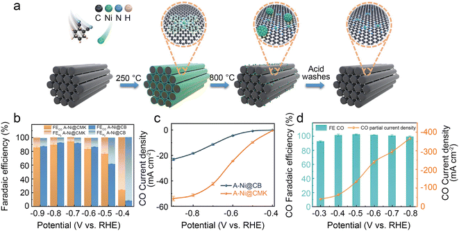 | ||
| Fig. 4 (a) Schematic illustration of the synthesis of A-Ni@CMK; (b) FECO and FEH2 of A-Ni@CMK and A-Ni@CB in the H-type cell; (c) jCO of A-Ni@CMK and A-Ni@CB in the H-type cell; and (d) electrocatalytic activity of A-Ni@CMK in the flow cell.40 Reprinted with permission from Wiley-VCH, copyright 2021. | ||
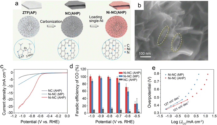 | ||
| Fig. 5 (a) Schematic illustration of the preparation route for Ni-NC(AHP); (b) FESEM images of Ni-NC(AHP); the dash circles indicate the openings and parallel walls of hollow plates; (c–e) CO2 electroreduction performance of samples; (c) LSV curves in CO2-saturated 0.5 M KHCO3 solution; (d) comparison of CO faradaic efficiency at various potentials; and (e) Tafel plots towards CO product.41 Reprinted with permission from Wiley-VCH, copyright 2021. | ||
To further design catalysts with favorable mass transfer and highly accessible discrete active sites, Li et al.42 developed a credible Ni-templated and Ni-catalyzed method for converting metallic Ni into single-Ni atoms anchored on hollow porous urchin-like N-doped carbon to synthesize a superior SAC (denoted as Ni-NC(HPU)) (Fig. 6a). The distinctive hollow thorns on the surface (Fig. 6b and c) contribute to a large external surface area and excellent conductivity, increasing the exposure of single-Ni sites and accelerating mass transfer, especially electron transfer. Meanwhile, this unusual shape does not affect the uniform atomic dispersion of Ni (Fig. 6d). The results of the examination of the H-type cells indicate that the main products are CO and H2. The FE of CO reaches 91% with a jCO of 24.7 mA cm−2 when operated at −0.8 V. Furthermore, in potentials ranging from −0.7 V to −0.9 V, the FE of CO remains above 83% (Fig. 6e and f). The high crystallinity of Ni-NC(HPU) results in good conductivity;61 thus, this material displays the lowest charge transfer resistance in the electrochemical impedance spectroscopy (EIS) test (Fig. 6g). This work provides new inspiration for synthesizing advanced single-atom catalysts with hollow porous structures for various energy storage and conversion applications.
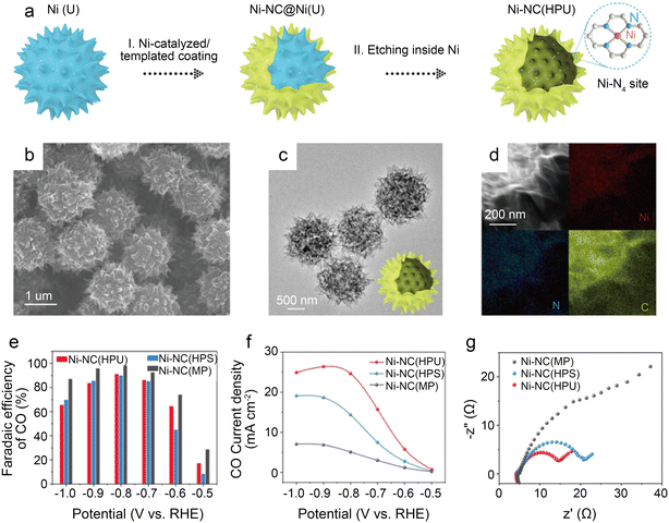 | ||
| Fig. 6 (a) Schematic illustration of the preparation strategy for Ni-NC(HPU); (b–d) electron microscopy characterizations of Ni-NC(HPU), (b) FESEM images; (c) low-magnification TEM image; (d) dark-field TEM image and EDX elemental mapping images; (e–g) CO2 electroreduction performance of samples; (e) comparison of CO FE of three samples at various potentials; (f) comparison of CO partial current density at various potentials; and (g) EIS plots obtained at −0.7 V vs. RHE.42 Reprinted with permission from Wiley-VCH, copyright 2022. | ||
3.2 Coordination structure regulation
Because CO2RR contains multiple PCET processes and the single atom centers of SACs are regarded as active sites, the coordination structures of the metal atomic centers are of particular importance to the electrocatalytic reaction. The typical Ni–N4 coordination structure with symmetric D4h square-planar geometry is unfavorable for electron transfer. Hence, breaking this symmetry is the key to enhancing CO2RR kinetics.62 The common strategies include tuning coordination numbers, creating vacancies, and diversifying coordination atom species.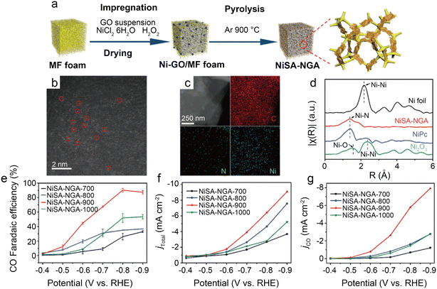 | ||
| Fig. 7 (a) Schematic illustration of the synthesis of NiSA-NGA; (b) HAADF-STEM image of NiSA-NGA; (c) STEM images and the corresponding energy-dispersive X-ray spectroscopy (EDS) elemental maps of C, N, and Ni for NiSA-NGA; (d) Fourier transformed EXAFS spectra of the Ni K-edge for Ni foil, NiSA-NGA, NiPc, and Ni2O3; (e) CO faradaic efficiency; (f) total current density; and (g) partial CO current density of NiSA-NGA catalysts versus electrolytic potentials.43 Reprinted with permission from Wiley-VCH, copyright 2019. | ||
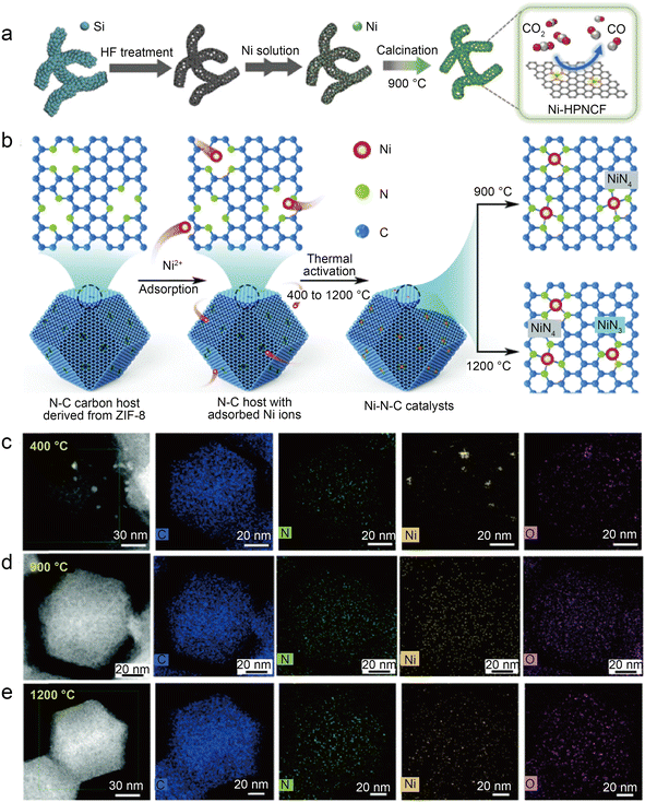 | ||
| Fig. 8 (a) Schematic representation of the synthesis of Ni-HPNCF.44 Reprinted with permission from Wiley-VCH, copyright 2023. (b) Synthesis scheme of the Ni–N–C catalysts using a nitrogen-doped carbon host to absorb Ni ions, followed by thermal activation at different temperatures to tune the Ni–N bond structures and establish the structure–property correlations; (c–e) HAADF-STEM and the corresponding EDS elemental mapping showing the homogeneous distribution of C, N, and Ni atoms on the surface for Ni–N–C activated at 900 °C and 1200 °C as compared to noticeable metallic clusters on Ni–N–C with 400 °C thermal activations. Temperature labels indicate activation temperature; samples were characterized at room temperature.45 Reprinted with permission from Royal Society of Chemistry, copyright 2022. | ||
To accurately control the coordination environment and number of Ni atoms, Li et al.45 explored a unique two-step method (Fig. 8b). In the first step, the particle size range of the ZIF-8 nanocrystal precursors was controlled by adjusting the concentration of zinc salt during the synthesis of ZIF-8. Through one-step carbonization, the precursors were retained in the derived carbon host. This step can produce nitrogen-doped carbon hosts with controlled morphology. In the second step, before thermal activation at relevant temperatures (400 °C, 900 °C, and 1200 °C) to form controlled Ni–N bonds, the Ni ions were introduced in the N-doped carbon host by chemisorption. The thermal activation temperature is vital to control the structure of Ni–N bonds in this method. HAADF-STEM and the corresponding EDS elemental mappings clearly demonstrate that Ni clusters gradually transform into atomically dispersed Ni sites at higher temperatures (Fig. 8c–e). Furthermore, the XAS reveals that Ni–N bonds become shorter at elevated thermal activation temperatures, which is associated with structural distortion in graphene. Besides, XPS indicates that Ni–N–C-1200 samples have less total and pyridinic nitrogen content than Ni–N–C-900, which can be attributed to higher temperatures, resulting in the loss of N atoms and favoring the formation of the Ni–N3 structure. Based on the EXAFS fitting, the Ni–N coordination number of Ni–N–C-1200 is 3.54, suggesting the coexistence of Ni–N3 sites and Ni–N4 sites. As in previous studies, the DFT calculations support the idea that Ni–N3 sites can enhance the activity of CO2RR as well as inhibit HER. However, Ni–N–C-900 performs best in a flow cell test with a jCO of 726 mA cm−2 and a CO FE of above 90%. This is because although Ni–N3 sites are more active in CO2-to-CO conversion and have better selectivity, high temperatures reduce the N and Ni atoms, thus significantly reducing the active site density. Notably, this work also discusses three possible configurations of NiN3 sites: NiN3, NiN3C1, and NiN3-vac. Of the three NiN3 sites modeled and the NiN4 site, the NiN3-vac site has the largest positive UL(CO2RR) − UL(HER) value, indicating that the NiN3-vac site could have high CO2RR selectivity.
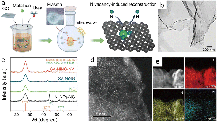 | ||
| Fig. 9 (a) Schematic illustration of microwave induced plasma-assisted synthesis for SACs; (b) transmission electron microscopy (TEM) image of SA-NiNG-NV; (c) X-ray diffraction (XRD) patterns of both catalysts SA-NiNG and SA-NiNG-NV, and control samples N-doped graphene (NG) and metallic Ni nanoparticles decorated NG (Ni NPs-NG); (d) high-angle annular dark field scanning transmission electron microscopy (HAADF-STEM) image of SA-NiNG-NV; and (e) EDS mapping images of SA-NiNG-NV.46 Reprinted with permission from Wiley-VCH, copyright 2021. | ||
Besides modulating the planar coordination environment of the Ni atom on the carbon network, the insertion of axial heteroatom coordination is also an effective strategy. According to the principles of organometallics, the NiII (i.e., the d8 species) has a strong tendency to form D4h square planar geometries and is less capable of forming axial bonds.63 For this reason, precise synthesis of M–N4–O structure with axial M–O coordination is an extremely difficult task. In classic biological substances with Fe–N4–Cl and Fe–N5 structures, the heterogeneous and metal atoms form specific coordination sites on the parallelogram. Inspired by this, Wang et al.48 modelled biological structures via an axial traction strategy (Fig. 10a). The XRD together with the TEM demonstrates that metal nanoparticles are effectively removed by acid-leaching treatment. The EDX element mapping images combined with XPS verify that coexisting N, O, and Ni atoms are uniformly dispersed on carbon substrates. According to the results of AC-STEM, EXAFS, EXANES and DFT calculations, it is concluded that four nitrogen atoms and one axial oxygen atom anchor the atomically dispersed Ni sites (inset of Fig. 10b). The Ni–N4–O/C electrocatalyst exhibits superior ECR performance with a maximum of 99.2% CO FE at −0.9 V. The CO FE can remain above 90% in a potential window ranging from −0.5 to −1.1 V, which is a wider range than that of conventional catalysts (−0.5 to −0.9 V). In comparison with the Ni–N4–PRO/C without an axial O atom, the extraordinary CO2RR activity of Ni–N4–O/C is further demonstrated to be due to the axial traction effect induced by the axial oxygen atom and the Ni–N4 site. Furthermore, this work proposes that, unlike the typical Ni–N4/C catalysts, the CO2 molecules react on the backside of graphene rather than on the side containing O atoms (Fig. 10c–f). Huang et al.49 reported a one-pot template-sacrificing pyrolysis strategy by decomposing the Mg(OH)2 template to create highly porous structures and synthesize catalysts with the same Ni–N4–O structure, as described above (Fig. 11a). At −0.76 V, the NiSA(0.3)-N-PGC shows a maximum CO FE of 97.2%. Overall experimental and theoretical calculations conclude that the outstanding properties are attributed to the induced charge asymmetry distribution and the higher electronegativity of the axially coordinated O atoms, which enhance the electronic delocalization at the central metal atom sites, resulting in lowering Gibbs free energy of the rate-limiting step, strengthening the bonding with *COOH, and weakening the bonding with *CO. In addition, porous structures formed by interlinked conductive mesh structures and interconnected thin plates with large specific surface areas greatly facilitate mass transport.
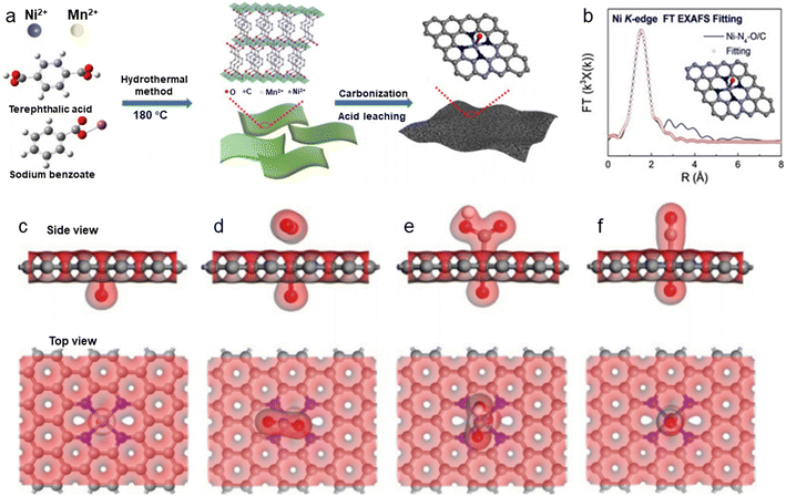 | ||
| Fig. 10 (a) Illustration of the synthesis process; (b) EXAFS fitting curves in R space. Inset: Corresponding schematic model of Ni–N4–O/C; (c)–(f) side view and top view of structural evolution of electrochemical CO2RR for Ni–N4–O/C (Ni cyan, N blue, O red, H white, C grey).48 Reprinted with permission from Wiley-VCH, copyright 2020. | ||
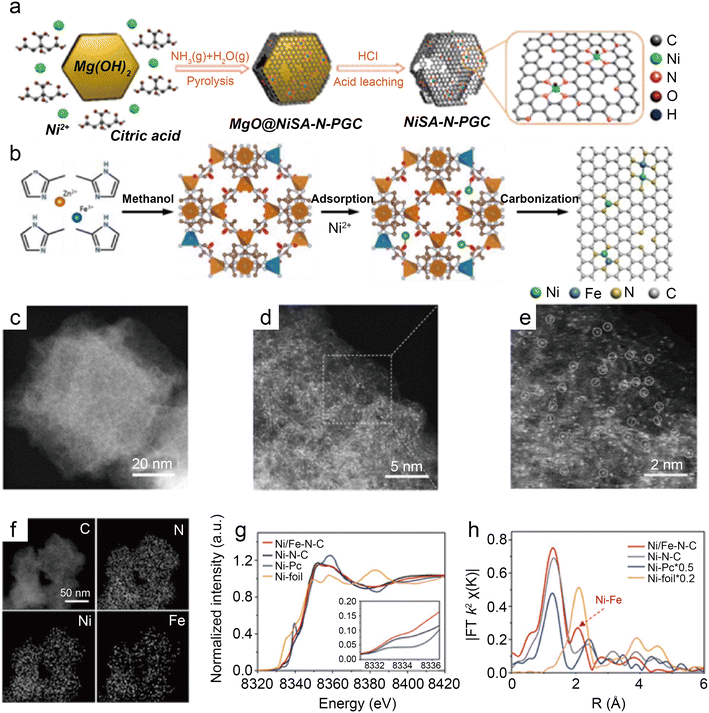 | ||
| Fig. 11 (a) Illustration of the synthesis of nickel single nickel atoms dispersed on nitrogen-doped porous graphitic carbon (NiSA-N-PGC).49 Reprinted with permission from American Chemical Society, copyright 2022; (b) scheme of the synthesis of Ni/Fe–N–C; (c) HAADF-STEM image; (d and e) enlarged HAADF-STEM images of Ni/Fe–N–C; (f) elemental mapping of Ni/Fe–N–C; (g) Ni K-edge XANES spectra of Ni/Fe–N–C, Ni–N–C, Fe–N–C, and Ni foil; and (h) Fourier transformation of the EXAFS spectra at R space.50 Reprinted with permission from Wiley-VCH, copyright 2019. | ||
The introduction of heteroatoms into the coordination structure not only affects the electron distribution of the central Ni atoms, but in some cases, the heteroatoms also coordinate with the Ni atoms to form dual site active centers, synergistically regulating the interaction with the reaction intermediates. Ma et al.64 investigated 27 types of catalysts with the structure of Ni–BXCYNZ (X + Y + Z = 4) via DFT calculations. B acts like a transition metal in many cases because its incompletely occupied valence electron d-orbital is so conducive to accepting and donating lone pairs of electrons. The results indicate that with the introduction of B, the Ni and B atoms are coordinated to form a dual active site, leading to various single or dual site adsorptions of reaction species. Consequently, the linear scaling relationship between *CO and *COOH adsorption is obviously diminished. Notably, in contrast to Ni–BXCYNZ (X = 0), the potential-determining step of Ni–BXCYNZ (X ≠ 0) changes to *CO desorption rather than *COOH formation. Overall, this work displays the tremendous potential of B to improve the CO2RR performance of Ni SACs. However, to the best of our knowledge, this structure has not yet been applied in experiments. It remains a great challenge.
As a transition metal, Ni has strong binding with H atoms, which enhances HER. Hu et al.65 introduced HER-inert In atoms to modulate the electronic structure of Cu atoms, which suppress HER while promoting CO2RR. This strategy proves that modulating the binding energy of single-atom sites with key intermediates by leading in different metal atoms is a promising approach. For instance, Ren et al.50 prepared the Ni/Fe–N–C by pyrolyzing the zeolitic imidazolate framework (Fig. 11b). Observations by HAADF-STEM and EDS analyses illustrate that single Ni and Fe atoms are homogeneously distributed without forming NPs (Fig. 11c–f). The analysis of XANES reveals distorted D4h symmetry in Ni/Fe–N–C and presumes that the D4h symmetry is distorted by another ligand (Fig. 11g). According to the Fourier transform (FT) k2-weighted χ(k) function of the EXAFS spectra, Ni/Fe–N–C has a distinct metal–metal peak at 2.06 Å, which is not found in pure Fe–N–C and Ni–N–C, confirming the presence of Ni–Fe coordination (Fig. 11h). In a wide potential ranging from −0.5 to −0.9 V, the Ni/Fe–N–C catalyst displays excellent selectivity for CO FE with over 90% and reaches a peak of 98% at−0.7 V. After 30 hours of electrocatalysis, it also shows impressive stability by retaining 99% initial selectivity. The TOF at −1.0 V of Ni/Fe–N–C (7682 h−1) is significantly larger than that of Fe–N–C (813 h−1) and Ni–N–C (3690 h−1), representing highly enhanced activity. The lower Tafel slope of Ni/Fe–N–C demonstrates the greatly enhanced kinetics of the rate-determining step. DFT calculations demonstrate that the Ni–Fe dual center can dramatically lower the reaction barrier, resulting in robust electrode durability. Moreover, when the monovalent Ni atom with the d9 electronic configuration performs as the catalytic active site, the intrinsic CO2RR activity of Ni SACs can be effectively enhanced.66 Zhu et al.51 designed a Ni–Cu coupled atom pair with a Ni 3d electronic configuration (Ni/Cu–N–C), which shows a high TOF of 20![[thin space (1/6-em)]](https://www.rsc.org/images/entities/char_2009.gif) 695 h−1 at −0.6 V with a maximum FE CO of 97.7%. The results of the XAS indicate that the Ni(I) species of Ni–Cu structures are the active sites for CO2RR. The Cu element is more electro-negative; thus, the d-orbital energy level of the Ni site can be increased while combining with Cu.67 Consequently, intermediates are more easily adsorbed because of anti-bonding states away from the Fermi energy level. The Ni–Cu structure greatly reduces the reaction potential and promotes CO2RR kinetics simultaneously. Recently, many studies about coordinating Ni sites with metallic atoms have been reported, and the communitive effect between adjacent single atoms is considered essential for improved catalysis.
695 h−1 at −0.6 V with a maximum FE CO of 97.7%. The results of the XAS indicate that the Ni(I) species of Ni–Cu structures are the active sites for CO2RR. The Cu element is more electro-negative; thus, the d-orbital energy level of the Ni site can be increased while combining with Cu.67 Consequently, intermediates are more easily adsorbed because of anti-bonding states away from the Fermi energy level. The Ni–Cu structure greatly reduces the reaction potential and promotes CO2RR kinetics simultaneously. Recently, many studies about coordinating Ni sites with metallic atoms have been reported, and the communitive effect between adjacent single atoms is considered essential for improved catalysis.
3.3 Surface modification
Regulation of coordination structures is the most straightforward way to alter the electronic distribution of central Ni atoms. In addition, non-coordinated regulation is a promising pathway for optimizing the electrocatalytic performance of Ni SACs. Specifically, it includes the structural modulation of the catalyst and reaction interface engineering.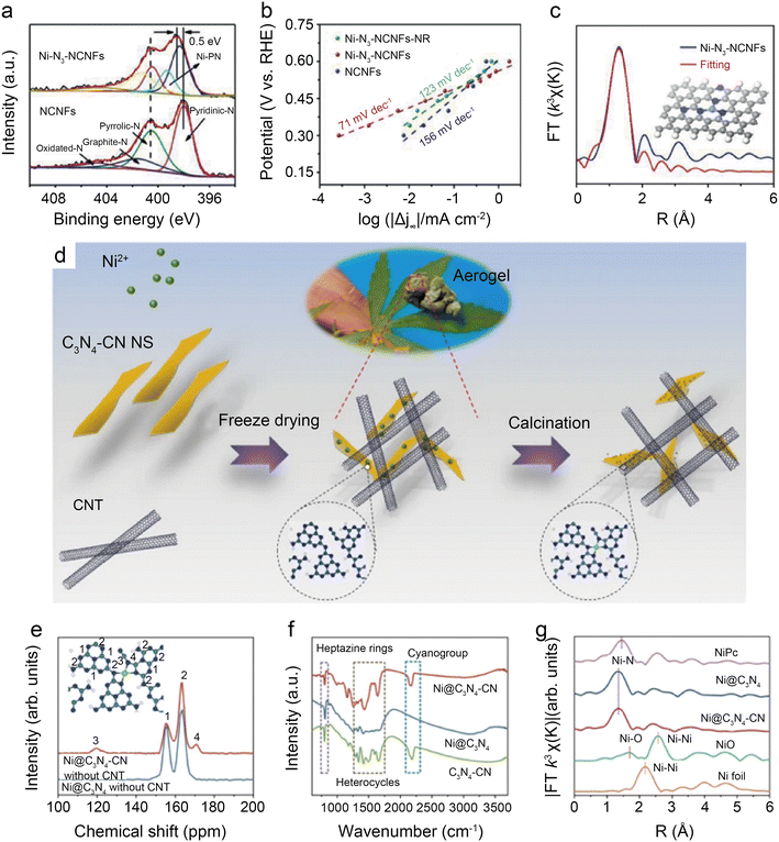 | ||
| Fig. 12 (a) Tafel slopes of Ni-N3-NCNFs-NR, Ni-N3-NCNFs, and NCNFs; (b) high-resolution N 1s spectra of Ni-N3-NCNFs and NCNFs; (c) fitting results for FT-EXAFS of Ni-N3-NCNFs, inset: optimized model for Ni-N3-NCNFs.52 Reprinted with permission from Wiley-VCH, copyright 2021; (d) schematic illustration of the preparation; (e) solid-state 13C MAS NMR spectra of Ni@C3N4–CN, Ni@C3N4 without CNT; (f) FT-IR spectra of Ni@C3N4–CN, Ni@C3N4 and C3N4–CN catalyst; and (g) k3 weighted Fourier transform spectra from EXAFS of Ni@C3N4–CN and Ni@C3N4.53 Reprinted with permission from Nature, copyright 2022. | ||
Wang et al.53 found that the addition of cyano to carbon-based substrates significantly facilitates the activation of CO2. As shown in Fig. 12d, the cyano-modified catalyst, designated as Ni@C3N4–CN, is prepared by salt-assisted and calcination methods. Solid-state 13C MAS NMR (Fig. 12e) and Fourier transform infrared (FT-IR) (Fig. 12f) demonstrate the existence of the –CN group in the carbon support. FT-EXAFS indicates the presence of Ni–N4 configuration in Ni@C3N4–CN, also further confirming that the optimization of performance is not derived from changes in active site structures (Fig. 12g). The results of DFT calculations suppose that the formation of CN groups weakens d–π conjugation between the metal atoms and the supports, thus reducing the charge transfer from the metal atoms to the supports and increasing the electron density around the central metal atoms. In the H-cell electrochemical test at −1.178 V, Ni@C3N4–CN enables remarkable TOF of ∼22![[thin space (1/6-em)]](https://www.rsc.org/images/entities/char_2009.gif) 000 h−1 and jCO of 46.8 mA cm−2. The CO FE is maintained above 90% even with a CO2 concentration of only 30%. When operating at −0.93 V in the flow cell with pure CO2, Ni@C3N4–CN displays −300 mA cm−2 current density with a CO FE of over 90%.
000 h−1 and jCO of 46.8 mA cm−2. The CO FE is maintained above 90% even with a CO2 concentration of only 30%. When operating at −0.93 V in the flow cell with pure CO2, Ni@C3N4–CN displays −300 mA cm−2 current density with a CO FE of over 90%.
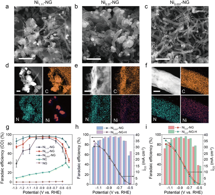 | ||
| Fig. 13 (a–c) SEM images showing abundant carbon-encapsulated Ni NPs, scale bar: 1 μm; (d–f) HAADF-STEM images and the corresponding EDS elemental mapping of C, N, Ni, scale bar: 200, 50, and 50 nm for (d–f), respectively; (g) the CO FEs of catalysts loaded on glassy carbon electrode at independent potentials ranging from −0.5 to −1.3 V (vs. RHE); (h and i) the CO FEs and CO partial current densities of Ni-NG and Ni-NG-H catalysts loaded on carbon paper (CP) at independent potentials from ranging −0.5 to −1.2 V (vs. RHE).54 Reprinted with permission from Wiley-VCH, copyright 2021. | ||
Using a brief Ni-metal organic framework-assisted method (Fig. 14a), Wen et al.56 prepared a series of Ni(NC)-based catalysts formed by different contents of Ni NPs and single Ni atoms. The EDS images demonstrate that the Ni atoms are uniformly dispersed in Ni(NC)-1, and the existence of Ni NPs is also confirmed by the presence of bright spots in some areas with the combination of HRTEM (Fig. 14b and c). Several characterization results indicate that Ni(NC)-1 contains more N elements and therefore modulates the electronic structure of surface Ni species. In contrast, more unmodified Ni–Ni species are present on the carbon layers of Ni(NC)-2 and Ni(NC)-3. Consequently, Ni(NC)-1 exhibits considerably more extraordinary electrochemical performance (Fig. 14d and e). In the flow cell, Ni(NC)-1 shows 99% maximum CO selectivity with a large j of −160 mA cm−2 at −1.82 V. This work demonstrates the possibility of activating electrocatalytically inactive sites into active sites by modulating the electronic environment of Ni species. However, the detailed functions of NPs and single-atom sites in CO2RR remain unclear. Bai et al.57 claimed that Ni NPs promote the decomposition of H2O to form *H, making it easier for adsorbed CO2 molecules to generate *COOH through PCET, while Ni single-atom sites can stimulate CO2 activation and CO desorption.
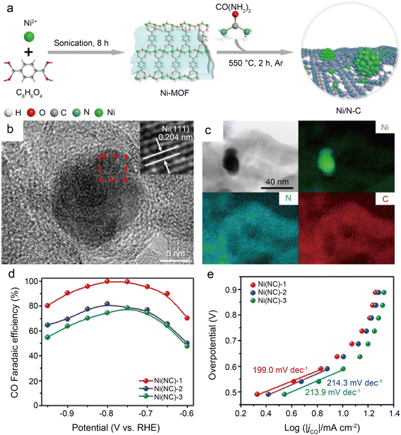 | ||
| Fig. 14 (a) Schematic illustration of the formation of Ni(NC) samples; (b) HRTEM images of Ni(NC)-1. The inset of (b) is the enlarged HRTEM image showing the (111) lattice fringe of Ni; (c) bright-field TEM image of Ni(NC)-1 and the corresponding element mapping images of Ni, N, and C; (d) faradic efficiencies of CO for the samples at various applied potentials; and (e) Tafel plots of jCO for the samples at various applied potentials.56 Reprinted with permission from American Chemical Society, copyright 2019. | ||
Some of the above works have proved that the coordination of the O atoms and the central Ni atoms can effectively break the symmetry of the electron density of the Ni–N4 sites to improve catalytic performance. However, the precise construction of the M–Nx–O structure remains a great challenge. Recently, it has been demonstrated that O atoms can modulate the performance of catalysts in the form of highly dispersed metal oxide particles without participating in coordination.72 Li et al.58 designed a simple carbonization coupled oxidation method for synthesizing NiO/Ni–N–C SACs modified with NiO clusters (Fig. 15a). HAADF-STEM images indicate the presence of NiO clusters, Ni NPs and Ni single atoms (Fig. 15b–d). The EDS images further reflect the uniform scatter of the N, Ni, and C elements on the carbon substrate (Fig. 15e). Analysis of XRD and XPS images leads to the conclusion that the Ni species are mainly present in the form of coordinated Ni–O and highly dispersed Ni–N sites in NiO/Ni–N–C-800, which is in agreement with the results of XAS, EXAFS, XANES and other characterization techniques. In a wide potential ranging from −0.9 to −1.3 V, the CO FE of NiO/Ni–N–C-800 remains over 90% (Fig. 15f). At −1.1 V, CO FE reaches a peak of 93%. The DFT calculation proposes greater properties of NiO/Ni–N–C-800 (Fig. 15g and h) because the NiO clusters reduce the energy barrier of CO2–CO conversion by enhancing the electronic delocalization of active sites. Besides, the hierarchical porous morphology of NiO/Ni–N–C-800 facilitates mass transfer and exposes more accessible active sites. This work presents advanced insights into adjusting the electronic structure of active sites by oxygen modulation.
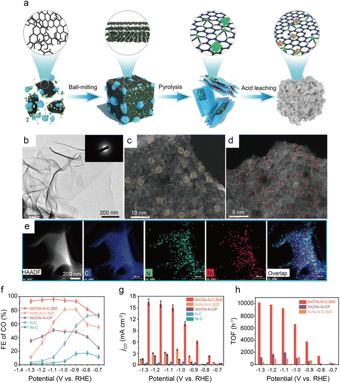 | ||
| Fig. 15 (a) Schematic diagram of the synthesis process for NiO/Ni–N–C; (b) TEM image (inset: SAED pattern) of NiO/Ni–N–C-800; (c and d) HAADF-STEM images of NiO/Ni–N–C-800. The yellow circles are identified as NiO clusters, and the small red circles are identified as single Ni atoms; (e) EDS mapping images of NiO/Ni–N–C-800; (f) FECO for various samples at different potentials; (g) jCO for various samples at different potentials; and (h) TOF of NiO/Ni–N–C-800, NiO/Ni–N–CP, and Ni/Ni–N–C-800 at different potentials.58 Reprinted with permission from Wiley-VCH, copyright 2022. | ||
4 Summary and perspectives
4.1 Summary
The catalytic reduction of CO2 into value-added fuels and chemicals via renewable electricity is accepted as an efficient solution to alleviating the energy crisis and greenhouse effect. SACs have received substantial research attention owing to their high atom utilization, abundant active sites and excellent catalytic performance. Besides, SACs have the advantages of both homogeneous and multiphase catalysis.73 Regarding the central metals of SACs, transition metals are the best choice owing to their special electronic structures, which can provide vacant d-orbitals to combine the key intermediates and reduce the activation energy barrier of CO2RR, thus increasing the intrinsic activity. CO2RR has a wide range of products, of which CO is a key feedstock for Fischer–Tropsch synthesis and is of high industrial value. In electrochemical tests, Ni SACs show more outstanding activity and selectivity than other transition metal SACs and therefore have been a hot topic of research. Based on DFT calculations and crystal field theory, the d-orbital of the central transition metal splits in a square planar field in the conventional M–N4 structure of SACs, and Ni is more likely to form vacant outermost d-orbitals compared with other transition metals (e.g. Fe, Co, and Cu). Such vacant orbitals facilitate the transfer of electrons from the C atom of the CO2 molecules to the Ni atom and promote the activation of liner CO2. In addition, in situ spectroscopic and theoretical thermodynamic studies indicate that Ni SACs overcome the free energy potential barrier of the CO2RR rate-determining step and benefit the generation of *COOH intermediates. Consequently, Ni SACs always have a higher selectivity for generating CO than other transition metal single-atom catalysts.This review begins by describing the pathway of CO generation via CO2RR and the characterization methods for determining the active site structures of Ni SACs. Following that, depending on different approaches to enhance electrocatalytic performance, the Ni SACs reported in recent years are divided into three groups:
(1) Different structures of supports. Carbon materials are popular catalyst substrates owing to their abundant sources, regulated structure, excellent chemical stability, and superior electrical conductivity. Besides their function as electrical conductors, carbon substrates also have an essential effect on the rate of mass transfer. Carbon black, graphene, and carbon nanotubes are examples of typical carbon substrates. To accelerate mass transfer and improve active site density, many substrates with a high specific surface area and many mesoporous channels are being explored for the synthesis of Ni SACs.
(2) Coordination structure regulation. Nitrogen-doped carbon facilitates the anchoring of central metal atoms and stabilizes coordination structures. The most common structure is Ni–N–C, with Ni–N4 as the conventional active center coordination structure. However, the symmetrical electronic structure is detrimental to the PCET process and diminishes the kinetics of CO2RR. Adjusting the coordination number, constructing vacancy defects, and varying the species of coordination atoms are prevalent strategies for breaking symmetric electronic structures. Among them, varying the species of coordination atoms includes the addition of dopants other than nitrogen on the carbon substrates (S, P, etc.), the introduction of axial heteroatom coordination (O, Cl, etc.), and the insertion of metal atoms to form dual active centers with nickel (Fe, Cu, etc.).
(3) Surface modification. Changing the coordination structure is the most straightforward way to break the symmetry of the electron distribution, but altering the surface structure and composition is also an effective strategy. Nitrogen has strong electronegativity, and when doped in excess, it can affect the electron distribution of the C atoms adjacent to the active site, accelerating the kinetics of CO2RR. The introduction of functional groups (e.g. –CN) on the substrate can boost the electron density of the active sites, thereby accelerating CO2 activation. The preparation of SACs inevitably produces NPs, which are inactive for CO2RR, but the addition of ultrathin N-doped carbon shells encapsulating Ni NPs and NiO clusters on the catalyst surface in appropriate amounts can enhance electrochemical performance.
4.2 Perspectives
Thus far, Ni–N–C has made outstanding progress in the direction of electrocatalytic reduction of CO2 to CO, but there are still many problems to overcome. An excellent Ni SAC should also have excellent atom utilization, activity, selectivity and stability. Subsequently, some perspectives on the existing challenges are then discussed.(1) Improving the singularity of coordination structures. The coordination structure is the most vital part of Ni SACs, yet regulating the microenvironment of the active center to synthesize active sites with a single coordination environment remains a great challenge. Currently, most reports attribute the average properties of the sample to overall catalytic performance, lacking rigor in demonstrating efficient active sites. Methods, such as flame spray pyrolysis, which provides a relatively homogeneous synthesis environment, hold the promise of achieving the singularity of coordination structures.
(2) Innovating coordination structure types. Recently, most studies have focused on modulating the coordination structure of SACs, which still fail to produce a significant increase in catalytic efficiency. The formation of super-coordinated structures using physical–chemical methods disrupting the original electronic structure equilibrium, replacing the species of coordination atoms and increasing or decreasing the number of coordination atoms of the active central atom in the catalytic material can change the intrinsic energy band structure, electrical conductivity and catalytic activity. It provides new opportunities to further improve the performance of catalysts. Both Fe–N5 and Co–N5 have been proven to greatly enhance catalytic activity,74–76 but investigations on Ni–N5 are still relatively few. The Ni–N4–O structure with axial O coordination shows remarkable catalytic properties. Xiao et al.77 have demonstrated that the Ni–N4–O2 structure has great promise for the electrosynthesis of H2O2, and it has great research value in applying this structure to CO2RR. Ultra-high coordination has the potential to achieve a quantum leap in properties, and ultra-low coordination structures, such as Ni–N2, are also well worth investigating.
(3) Designing multi-sites catalysts. DACs can not only reduce the activation barriers of CO2RR but also break the linear scaling relation to further improve selectivity. Ni is often combined with other metal atoms to form dual-site catalysts, and owing to its special electronic structure, the catalysts always show good synergetic effects to promote catalytic efficiency. Therefore, expanding the number of active sites to create multi-site catalysts holds considerable promise. Moreover, if each site plays a distinct role, such as in one dual-site catalyst in which the Ni site is responsible for the adsorption of *COOH intermediates and the Cu site is used to promote C–C coupling, there is a possibility of generating multi-carbon products with high selectivity.
(4) Improving the loading of Ni. The loading of Ni is positively correlated with the intrinsic activity of the catalyst. However, according to the present reports, the loading of SACs is usually less than 5%. This is because it is difficult to improve the single-atom stability and inhibit the agglomeration of metal atoms while increasing the loading with the current synthesis methods. After a long reaction, Ni atoms tend to agglomerate to form nanoparticles that facilitate HER. Therefore, stabilizing the central metal atoms also contributes to the stability of the catalyst performance. Creating defects on the N-doped carbon substrates before inserting Ni atoms can help stabilize the structure of active sites, while microwave plasma induction and femtosecond lasers are all worthwhile synthetic approaches. To achieve industrial applications, it is not only desirable to increase the loading for achieving current densities for industrial applications (>200 mA cm−2) but also to explore synthetic methods that can produce catalysts on a large scale.
(5) Developing more types of substrates. The framework of substrates considerably influences catalytic properties. However, it is still a challenge to expand the types of substrates, with N-doped carbon being the most common. Synthesizing single-atom alloys by loading metal atoms on metal substrates has the potential to display substantial synergistic effects, disrupt the linear scaling relation, and promote multiphase catalysis. Aerogels, for example, are three-dimensional porous structures with a huge surface area that improves the exposure of active sites, isolates metal atoms in space and inhibits agglomeration.
(6) Exploring more operando characterization techniques. CO2RR involves complex PCET processes, and the development of operando characterization techniques is key to identifying the real active sites and tracking specific reaction pathways. Besides, operando characterization technologies can reveal the stability of the catalyst under reaction conditions, distinguish the species of key intermediates and clarify the influence of reaction conditions, which can be of great significance in designing catalysts with high activity for generating target products. To date, the main experimental approach to explore the CO2RR mechanism is through the analysis of ex situ characterization (TEM, XAS, XPS, etc.) of the catalyst before and after CO2RR. However, surface reconstruction, morphological transformation and active site evolution usually occur during the reaction process, so these ex situ methods cannot capture important information about the real CO2RR process. Although progress has been made in in situ IR, in situ Raman and in situ electron microscopy, the application is still limited. The small size of SACs makes it crucial to develop in situ techniques to directly observe the evolution of active sites at atomic resolution. Exploring more techniques, such as in situ SEM, which can visualize individual molecules and atoms adsorbed on the catalyst surface and monitor the configuration of intermediates in real-time, can help to clarify the catalytic mechanisms. Imaging the morphology and activity of the active center in conjunction with reaction devices is vital to reveal reaction mechanisms and design catalytic systems.
(7) Optimizing electrolytic cells. For electrochemical testing, H-cells and flow cells are the most popular choices. The H-cell is a simple device. However, the tank pressure is too high, and the test current density is limited. The flow cell is more compact when combined with a gas diffusion electrode, which significantly improves the mass transfer efficiency, but the energy efficiency and reaction life are still far from the industrial requirements. The membrane electrode assembly cell (MEA cell) has great industrial applications, as the cathode is separated from the anode only by an ion exchange membrane, which greatly reduces the internal resistance and increases the reaction efficiency, and has great prospects for industrial applications. However, there are still many issues that are worth discussing in terms of testing methods, such as feeding methods and electrode structures. Recently, the solid oxide electrolytic cell (SOEC) has gained popularity because of its advantages of high energy efficiency and high product selectivity. Importantly, under typical SOEC operating conditions, CO is the only product of CO2RR. In addition, SOEC operates at high temperatures, which inhibits the formation of NPs from Ni SACs during the reaction. Furthermore, the use of SOECs to produce high-purity CO for CO reduction, such as cascade systems, is projected to produce multi-carbon products for upgrading the products.
(8) Investigating the microscopic mechanisms of electrolytes. The pH and ionic type of the electrolyte crucially affect the rate of mass transfer and the stability of the reaction intermediates. Because alkaline electrolytes can inhibit HER, cathodic electrolytes, such as KHCO3, K2CO3, and KOH, are frequently used. However, alkaline electrolytes are prone to form carbonate, which harms single-pass CO2 utilization. Acidic electrolytes have the potential to increase single-pass CO2 utilization but are prone to HER. The addition of alkali metal ions to a strongly acidic electrolyte has been confirmed to inhibit HER. Recently, ionic liquid (IL) electrolytes have attracted attention owing to their high CO2 solubility.78 The IL electrolytes can modulate the three-phase interface and significantly increase the current density while increasing the single-pass CO2 utilization. Furthermore, bulk ionic liquid electrolytes have high viscosity, slow diffusion rate and low ionic conductivity. When added to Ni SACs with porous structures, they can develop the secondary co-catalyst phase and improve catalytic performance. Ni SACs still have many growth opportunities and are expected to play a more active role in CO2RR in the future.
Author contributions
ZiYan Yang: conceptualization, writing-original draft. Rongzhen Chen: writing-review and editing. Ling Zhang: supervision. Yuhang Li: supervision, writing-review and editing. Chunzhong Li: supervision.Conflicts of interest
There are no conflicts to declare.Acknowledgements
This work was supported by the National Natural Science Foundation of China (22322805, 22178104, U22B20143), Shanghai Municipal Science and Technology Major Project, the Shanghai Scientific and Technological Innovation Project (22dz1205900), “the Fundamental Research Funds for the Central Universities”, and Shanghai Rising-Star Program (23QA1402200).References
- J. Zhang, C. Guo, S. Fang, X. Zhao, L. Li, H. Jiang, Z. Liu, Z. Fan, W. Xu, J. Xiao and M. Zhong, Accelerating electrochemical CO2 reduction to multi-carbon products via asymmetric intermediate binding at confined nanointerfaces, Nat. Commun., 2023, 14, 1298 CrossRef CAS PubMed.
- J. Gao, A. Bahmanpour, O. Kröcher, S. M. Zakeeruddin, D. Ren and M. Grätzel, Electrochemical synthesis of propylene from carbon dioxide on copper nanocrystals, Nat. Chem., 2023, 15, 705–713 CrossRef CAS PubMed.
- S. Wang, L. Wang, D. Wang and Y. Li, Recent advances of single-atom catalysts in CO2 conversion, Energy Environ. Sci., 2023, 16, 2759–2803 RSC.
- S. Das, J. Pérez-Ramírez, J. Gong, N. Dewangan, K. Hidajat, B. C. Gates and S. Kawi, Core-shell structured catalysts for thermocatalytic, photocatalytic, and electrocatalytic conversion of CO2, Chem. Soc. Rev., 2020, 49, 2937–3004 RSC.
- S. Dongare, O. K. Coskun, E. Cagli, K. Y. C. Lee, G. Rao, R. D. Britt, L. A. Berben and B. Gurkan, A bifunctional ionic liquid for capture and electrochemical conversion of CO2 to CO over silver, ACS Catal., 2023, 13, 7812–7821 CrossRef CAS PubMed.
- P.-C. Chen, C. Chen, Y. Yang, A. L. Maulana, J. Jin, J. Feijoo and P. Yang, Chemical and structural evolution of AgCu catalysts in electrochemical CO2 reduction, J. Am. Chem. Soc., 2023, 145, 10116–10125 CrossRef CAS PubMed.
- M.-G. Kim, J. Park, Y. Choi, H. C. Song, S.-H. Kim, K.-M. Bang, H. C. Ham, N.-K. Kim, D. H. Won, B. K. Min, S. J. Yoo and W. Kim, Cuir nanoparticles for electrochemical reduction of CO2 to t-BuOH, Adv. Energy Mater., 2023, 13, 2300749 CrossRef CAS.
- Y. Jia, H.-S. Hsu, W.-C. Huang, D.-W. Lee, S.-W. Lee, T.-Y. Chen, L. Zhou, J.-H. Wang, K.-W. Wang and S. Dai, Probing the roles of indium oxides on copper catalysts for enhanced selectivity during CO2-to-CO electrochemical reduction, Nano Lett., 2023, 23, 2262–2268 CrossRef CAS PubMed.
- K. Zhang, J. Wang, W. Zhang, H. Yin, J. Han, X. Yang, W. Fan, Y. Zhang and P. Zhang, Regulated surface electronic states of CuNi nanoparticles through metal-support interaction for enhanced electrocatalytic CO2 reduction to ethanol, Small, 2023, 19, 2300281 CrossRef CAS PubMed.
- Y. Xu, Y. Guo, Y. Sheng, H. Yu, K. Deng, Z. Wang, X. Li, H. Wang and L. Wang, Selective CO2 electroreduction to formate on polypyrrole-modified oxygen vacancy-rich Bi2O3 nanosheet precatalysts by local microenvironment modulation, Small, 2023, 19, 2300001 CrossRef CAS PubMed.
- M. G. Lee, X.-Y. Li, A. Ozden, J. Wicks, P. Ou, Y. Li, R. Dorakhan, J. Lee, H. K. Park, J. W. Yang, B. Chen, J. Abed, R. dos Reis, G. Lee, J. E. Huang, T. Peng, Y.-H. Chin, D. Sinton and E. H. Sargent, Selective synthesis of butane from carbon monoxide using cascade electrolysis and thermocatalysis at ambient conditions, Nat. Catal., 2023, 6, 310–318 CrossRef CAS.
- K. Qi, Y. Zhang, N. Onofrio, E. Petit, X. Cui, J. Ma, J. Fan, H. Wu, W. Wang, J. Li, J. Liu, Y. Zhang, Y. Wang, G. Jia, J. Wu, L. Lajaunie, C. Salameh and D. Voiry, Unlocking direct CO2 electrolysis to C3 products via electrolyte supersaturation, Nat. Catal., 2023, 6, 319–331 CrossRef CAS.
- M. B. Ross, P. De Luna, Y. Li, C.-T. Dinh, D. Kim, P. Yang and E. H. Sargent, Designing materials for electrochemical carbon dioxide recycling, Nat. Catal., 2019, 2, 648–658 CrossRef CAS.
- Y. Y. Birdja, E. Pérez-Gallent, M. C. Figueiredo, A. J. Göttle, F. Calle-Vallejo and M. T. M. Koper, Advances and challenges in understanding the electrocatalytic conversion of carbon dioxide to fuels, Nat. Energy, 2019, 4, 732–745 CrossRef CAS.
- C. Hu, Y. Zhang, A. Hu, Y. Wang, X. Wei, K. Shen, L. Chen and Y. Li, Near- and long-range electronic modulation of single metal sites to boost CO2 electrocatalytic reduction, Adv. Mater., 2023, 35, 2209298 CrossRef CAS PubMed.
- S. C. Sarma, J. Barrio, A. Bagger, A. Pedersen, M. Gong, H. Luo, M. Wang, S. Favero, C.-X. Zhao, Q. Zhang, A. Kucernak, M.-M. Titirici and I. E. L. Stephens, Reaching the fundamental limitation in CO2 reduction to CO with single atom catalysts, Adv. Funct. Mater., 2023, 33, 2302468 CrossRef CAS.
- S. Chen, J. Chen, Y. Li, S. Tan, X. Liao, T. Zhao, K. Zhang, E. Hu, F. Cheng and H. Wang, Fe-N4O-C nanoplates covalently bonding on graphene for efficient CO2 electroreduction and Zn-CO2 batteries, Adv. Funct. Mater., 2023, 33, 2300801 CrossRef CAS.
- J. Wang, Y.-C. Huang, Y. Wang, H. Deng, Y. Shi, D. Wei, M. Li, C.-L. Dong, H. Jin, S. S. Mao and S. Shen, Atomically dispersed metal–nitrogen–carbon catalysts with d-orbital electronic configuration-dependent selectivity for electrochemical CO2-to-CO reduction, ACS Catal., 2023, 13, 2374–2385 CrossRef CAS.
- Y. Zhou, A. J. Martín, F. Dattila, S. Xi, N. López, J. Pérez-Ramírez and B. S. Yeo, Long-chain hydrocarbons by CO2 electroreduction using polarized nickel catalysts, Nat. Catal., 2022, 5, 545–554 CrossRef CAS.
- S. Nitopi, E. Bertheussen, S. B. Scott, X. Liu, A. K. Engstfeld, S. Horch, B. Seger, I. E. L. Stephens, K. Chan, C. Hahn, J. K. Nørskov, T. F. Jaramillo and I. Chorkendorff, Progress and perspectives of electrochemical CO2 reduction on copper in aqueous electrolyte, Chem. Rev., 2019, 119, 7610–7672 CrossRef CAS PubMed.
- F. Pan and Y. Yang, Designing CO2 reduction electrode materials by morphology and interface engineering, Energy Environ. Sci., 2020, 13, 2275–2309 RSC.
- L. R. L. Ting and B. S. Yeo, Recent advances in understanding mechanisms for the electrochemical reduction of carbon dioxide, Curr. Opin. Electrochem., 2018, 8, 126–134 CrossRef CAS.
- M. Li, H. Wang, W. Luo, P. C. Sherrell, J. Chen and J. Yang, Heterogeneous single-atom catalysts for electrochemical CO2 reduction reaction, Adv. Mater., 2020, 32, 2001848 CrossRef CAS PubMed.
- H. Liu, Y. Zhu, J. Ma, Z. Zhang and W. Hu, Recent advances in atomic-level engineering of nanostructured catalysts for electrochemical CO2 reduction, Adv. Funct. Mater., 2020, 30, 1910534 CrossRef CAS.
- K. Jiang, S. Siahrostami, A. J. Akey, Y. Li, Z. Lu, J. Lattimer, Y. Hu, C. Stokes, M. Gangishetty, G. Chen, Y. Zhou, W. Hill, W.-B. Cai, D. Bell, K. Chan, J. K. Nørskov, Y. Cui and H. Wang, Transition-metal single atoms in a graphene shell as active centers for highly efficient artificial photosynthesis, Chem, 2017, 3, 950–960 CAS.
- A. Wang, J. Li and T. Zhang, Heterogeneous single-atom catalysis, Nat. Rev. Chem., 2018, 2, 65–81 CrossRef CAS.
- U. I. Kramm, J. Herranz, N. Larouche, T. M. Arruda, M. Lefèvre, F. Jaouen, P. Bogdanoff, S. Fiechter, I. Abs-Wurmbach, S. Mukerjee and J.-P. Dodelet, Structure of the catalytic sites in Fe/N/C-catalysts for O2-reduction in pem fuel cells, Phys. Chem. Chem. Phys., 2012, 14, 11673–11688 RSC.
- U. Tylus, Q. Jia, K. Strickland, N. Ramaswamy, A. Serov, P. Atanassov and S. Mukerjee, Elucidating oxygen reduction active sites in pyrolyzed metal–nitrogen coordinated non-precious-metal electrocatalyst systems, J. Phys. Chem. C, 2014, 118, 8999–9008 CrossRef CAS PubMed.
- A. Zitolo, V. Goellner, V. Armel, M.-T. Sougrati, T. Mineva, L. Stievano, E. Fonda and F. Jaouen, Identification of catalytic sites for oxygen reduction in iron- and nitrogen-doped graphene materials, Nat. Mater., 2015, 14, 937–942 CrossRef CAS PubMed.
- D. M. Koshy, A. T. Landers, D. A. Cullen, A. V. Ievlev, H. M. Meyer Iii, C. Hahn, Z. Bao and T. F. Jaramillo, Direct characterization of atomically dispersed catalysts: Nitrogen-coordinated Ni sites in carbon-based materials for CO2 electroreduction, Adv. Energy Mater., 2020, 10, 2001836 CrossRef CAS.
- D. M. Koshy, S. Chen, D. U. Lee, M. B. Stevens, A. M. Abdellah, S. M. Dull, G. Chen, D. Nordlund, A. Gallo, C. Hahn, D. C. Higgins, Z. Bao and T. F. Jaramillo, Understanding the origin of highly selective CO2 electroreduction to CO on Ni,N-doped carbon catalysts, Angew. Chem., Int. Ed., 2020, 59, 4043–4050 CrossRef CAS PubMed.
- C. Zhang, L. Shahcheraghi, F. Ismail, H. Eraky, H. Yuan, A. P. Hitchcock and D. Higgins, Chemical structure and distribution in nickel–nitrogen–carbon catalysts for CO2 electroreduction identified by scanning transmission x-ray microscopy, ACS Catal., 2022, 12, 8746–8760 CrossRef CAS PubMed.
- R. M. Arán-Ais, D. Gao and B. Roldan Cuenya, Structure- and electrolyte-sensitivity in CO2 electroreduction, Acc. Chem. Res., 2018, 51, 2906–2917 CrossRef PubMed.
- W. Ju, A. Bagger, G.-P. Hao, A. S. Varela, I. Sinev, V. Bon, B. Roldan Cuenya, S. Kaskel, J. Rossmeisl and P. Strasser, Understanding activity and selectivity of metal-nitrogen-doped carbon catalysts for electrochemical reduction of CO2, Nat. Commun., 2017, 8, 944 CrossRef PubMed.
- P. Su, K. Iwase, S. Nakanishi, K. Hashimoto and K. Kamiya, Nickel-nitrogen-modified graphene: An efficient electrocatalyst for the reduction of carbon dioxide to carbon monoxide, Small, 2016, 12, 6083–6089 CrossRef CAS PubMed.
- K. Jiang, S. Siahrostami, T. Zheng, Y. Hu, S. Hwang, E. Stavitski, Y. Peng, J. Dynes, M. Gangisetty, D. Su, K. Attenkofer and H. Wang, Isolated Ni single atoms in graphene nanosheets for high-performance CO2 reduction, Energy Environ. Sci., 2018, 11, 893–903 RSC.
- H. Wang, G. Liu, C. Chen, W. Tu, Y. Lu, S. Wu, D. O'Hare and R. Xu, Single-Ni sites embedded in multilayer nitrogen-doped graphene derived from amino-functionalized MOF for highly selective CO2 electroreduction, ACS Sustainable Chem. Eng., 2021, 9, 3792–3801 CrossRef CAS.
- W. Zheng, C. Guo, J. Yang, F. He, B. Yang, Z. Li, L. Lei, J. Xiao, G. Wu and Y. Hou, Highly active metallic nickel sites confined in N-doped carbon nanotubes toward significantly enhanced activity of CO2 electroreduction, Carbon, 2019, 150, 52–59 CrossRef CAS.
- Y. Cheng, S. Zhao, B. Johannessen, J.-P. Veder, M. Saunders, M. R. Rowles, M. Cheng, C. Liu, M. F. Chisholm, R. De Marco, H.-M. Cheng, S.-Z. Yang and S. P. Jiang, Atomically dispersed transition metals on carbon nanotubes with ultrahigh loading for selective electrochemical carbon dioxide reduction, Adv. Mater., 2018, 30, 1706287 CrossRef PubMed.
- B. Chen, B. Li, Z. Tian, W. Liu, W. Liu, W. Sun, K. Wang, L. Chen and J. Jiang, Enhancement of mass transfer for facilitating industrial-level CO2 electroreduction on atomic Ni-N4 sites, Adv. Energy Mater., 2021, 11, 2102152 CrossRef CAS.
- Y. Li, S. L. Zhang, W. Cheng, Y. Chen, D. Luan, S. Gao and X. W. Lou, Loading single-Ni atoms on assembled hollow N-rich carbon plates for efficient CO2 electroreduction, Adv. Mater., 2022, 34, 2105204 CrossRef CAS PubMed.
- Y. Li, X. F. Lu, S. Xi, D. Luan, X. Wang and X. W. Lou, Synthesis of N-doped highly graphitic carbon urchin-like hollow structures loaded with single-Ni atoms towards efficient CO2 electroreduction, Angew. Chem., Int. Ed., 2022, 61, e202201491 CrossRef CAS PubMed.
- K. Mou, Z. Chen, X. Zhang, M. Jiao, X. Zhang, X. Ge, W. Zhang and L. Liu, Highly efficient electroreduction of CO2 on nickel single-atom catalysts: Atom trapping and nitrogen anchoring, Small, 2019, 15, 1903668 CrossRef CAS PubMed.
- I. Song, Y. Eom, P. M. Austeria, D. H. Hong, M. Balamurugan, R. Boppella, D. H. Kim and T. K. Kim, Geometric and electronic structural engineering of isolated Ni single atoms for a highly efficient CO2 electroreduction, Small, 2023, 19, 2300049 CrossRef CAS PubMed.
- Y. Li, N. M. Adli, W. Shan, M. Wang, M. J. Zachman, S. Hwang, H. Tabassum, S. Karakalos, Z. Feng, G. Wang, Y. C. Li and G. Wu, Atomically dispersed single Ni site catalysts for high-efficiency CO2 electroreduction at industrial-level current densities, Energy Environ. Sci., 2022, 15, 2108–2119 RSC.
- C. Jia, S. Li, Y. Zhao, R. K. Hocking, W. Ren, X. Chen, Z. Su, W. Yang, Y. Wang, S. Zheng, F. Pan and C. Zhao, Nitrogen vacancy induced coordinative reconstruction of single-atom Ni catalyst for efficient electrochemical CO2 reduction, Adv. Funct. Mater., 2021, 31, 2107072 CrossRef CAS.
- C. Jia, X. Tan, Y. Zhao, W. Ren, Y. Li, Z. Su, S. C. Smith and C. Zhao, Sulfur-dopant-promoted electroreduction of CO2 over coordinatively unsaturated Ni-N2 moieties, Angew. Chem., Int. Ed., 2021, 60, 23342–23348 CrossRef CAS PubMed.
- X. Wang, Y. Wang, X. Sang, W. Zheng, S. Zhang, L. Shuai, B. Yang, Z. Li, J. Chen, L. Lei, N. M. Adli, M. K. H. Leung, M. Qiu, G. Wu and Y. Hou, Dynamic activation of adsorbed intermediates via axial traction for the promoted electrochemical CO2 reduction, Angew. Chem., Int. Ed., 2021, 60, 4192–4198 CrossRef CAS PubMed.
- M. Huang, B. Deng, X. Zhao, Z. Zhang, F. Li, K. Li, Z. Cui, L. Kong, J. Lu, F. Dong, L. Zhang and P. Chen, Template-sacrificing synthesis of well-defined asymmetrically coordinated single-atom catalysts for highly efficient CO2 electrocatalytic reduction, ACS Nano, 2022, 16, 2110–2119 CrossRef CAS PubMed.
- W. Ren, X. Tan, W. Yang, C. Jia, S. Xu, K. Wang, S. C. Smith and C. Zhao, Isolated diatomic Ni-Fe metal–nitrogen sites for synergistic electroreduction of CO2, Angew. Chem., Int. Ed., 2019, 58, 6972–6976 CrossRef CAS PubMed.
- J. Zhu, M. Xiao, D. Ren, R. Gao, X. Liu, Z. Zhang, D. Luo, W. Xing, D. Su, A. Yu and Z. Chen, Quasi-covalently coupled Ni–Cu atomic pair for synergistic electroreduction of CO2, J. Am. Chem. Soc., 2022, 144, 9661–9671 CrossRef CAS PubMed.
- W. Zheng, Y. Wang, L. Shuai, X. Wang, F. He, C. Lei, Z. Li, B. Yang, L. Lei, C. Yuan, M. Qiu, Y. Hou and X. Feng, Highly boosted reaction kinetics in carbon dioxide electroreduction by surface-introduced electronegative dopants, Adv. Funct. Mater., 2021, 31, 2008146 CrossRef CAS.
- Q. Wang, K. Liu, K. Hu, C. Cai, H. Li, H. Li, M. Herran, Y.-R. Lu, T.-S. Chan, C. Ma, J. Fu, S. Zhang, Y. Liang, E. Cortés and M. Liu, Attenuating metal-substrate conjugation in atomically dispersed nickel catalysts for electroreduction of CO2 to CO, Nat. Commun., 2022, 13, 6082 CrossRef CAS PubMed.
- S. Liang, Q. Jiang, Q. Wang and Y. Liu, Revealing the real role of nickel decorated nitrogen-doped carbon catalysts for electrochemical reduction of CO2 to CO, Adv. Energy Mater., 2021, 11, 2101477 CrossRef CAS.
- F. Wang, G. Wang, P. Deng, Y. Chen, J. Li, D. Wu, Z. Wang, C. Wang, Y. Hua and X. Tian, Ultrathin nitrogen-doped carbon encapsulated Ni nanoparticles for highly efficient electrochemical CO2 reduction and aqueous Zn- CO2 batteries, Small, 2023, 19, 2301128 CrossRef CAS PubMed.
- C. F. Wen, F. Mao, Y. Liu, X. Y. Zhang, H. Q. Fu, L. R. Zheng, P. F. Liu and H. G. Yang, Nitrogen-stabilized low-valent Ni motifs for efficient CO2 electrocatalysis, ACS Catal., 2020, 10, 1086–1093 CrossRef CAS.
- S. Bai, L. Tan, C. Ning, G. Liu, Z. Wu, T. Shen, L. Zheng and Y.-F. Song, Revealing the kinetic balance between proton-feeding and hydrogenation in CO2 electroreduction, Small, 2023, 19, 2300581 CrossRef CAS PubMed.
- H. Li, K. Gan, R. Li, H. Huang, J. Niu, Z. Chen, J. Zhou, Y. Yu, J. Qiu and X. He, Highly dispersed NiO clusters induced electron delocalization of Ni-N-C catalysts for enhanced CO2 electroreduction, Adv. Funct. Mater., 2023, 33, 2208622 CrossRef CAS.
- T. N. Nguyen, M. Salehi, Q. V. Le, A. Seifitokaldani and C. T. Dinh, Fundamentals of electrochemical CO2 reduction on single-metal-atom catalysts, ACS Catal., 2020, 10, 10068–10095 CrossRef.
- T. Wang, J. Wang, C. Lu, K. Jiang, S. Yang, Z. Ren, J. Zhang, X. Liu, L. Chen, X. Zhuang and J. Fu, Single-atom anchored curved carbon surface for efficient CO2 electro-reduction with nearly 100% CO selectivity and industrially-relevant current density, Adv. Mater., 2023, 35, 2205553 CrossRef CAS PubMed.
- F. Yu, H. Zhou, Z. Zhu, J. Sun, R. He, J. Bao, S. Chen and Z. Ren, Three-dimensional nanoporous iron nitride film as an efficient electrocatalyst for water oxidation, ACS Catal., 2017, 7, 2052–2057 CrossRef CAS.
- H. Kim, D. Shin, W. Yang, D. H. Won, H.-S. Oh, M. W. Chung, D. Jeong, S. H. Kim, K. H. Chae, J. Y. Ryu, J. Lee, S. J. Cho, J. Seo, H. Kim and C. H. Choi, Identification of single-atom Ni site active toward electrochemical CO2 conversion to CO, J. Am. Chem. Soc., 2021, 143, 925–933 CrossRef CAS PubMed.
- C. J. Ballhausen and M. A. Weiner, Introduction to ligand field theory, J. Electrochem. Soc., 1963, 110, 97Cb CrossRef.
- M. Ma, F. Li and Q. Tang, Coordination environment engineering on nickel single-atom catalysts for CO2 electroreduction, Nanoscale, 2021, 13, 19133–19143 RSC.
- C. Hu, Y. Wang, J. Chen, H.-F. Wang, K. Shen, K. Tang, L. Chen and Y. Li, Main-group metal single-atomic regulators in dual-metal catalysts for enhanced electrochemical CO2 reduction, Small, 2022, 18, 2201391 CrossRef CAS PubMed.
- H. B. Yang, S.-F. Hung, S. Liu, K. Yuan, S. Miao, L. Zhang, X. Huang, H.-Y. Wang, W. Cai, R. Chen, J. Gao, X. Yang, W. Chen, Y. Huang, H. M. Chen, C. M. Li, T. Zhang and B. Liu, Atomically dispersed Ni(i) as the active site for electrochemical CO2 reduction, Nat. Energy, 2018, 3, 140–147 CrossRef CAS.
- S. Schnur and A. Groß, Strain and coordination effects in the adsorption properties of early transition metals: A density-functional theory study, Phys. Rev. B: Condens. Matter Mater. Phys., 2010, 81, 033402 CrossRef.
- X. Li, Y. Zeng, C.-W. Tung, Y.-R. Lu, S. Baskaran, S.-F. Hung, S. Wang, C.-Q. Xu, J. Wang, T.-S. Chan, H. M. Chen, J. Jiang, Q. Yu, Y. Huang, J. Li, T. Zhang and B. Liu, Unveiling the in situ generation of a monovalent Fe(i) site in the single-Fe-atom catalyst for electrochemical CO2 reduction, ACS Catal., 2021, 11, 7292–7301 CrossRef CAS.
- W. Liu, L. Zhang, X. Liu, X. Liu, X. Yang, S. Miao, W. Wang, A. Wang and T. Zhang, Discriminating catalytically active FeNx species of atomically dispersed Fe-N-C catalyst for selective oxidation of the C-H bond, J. Am. Chem. Soc., 2017, 139, 10790–10798 CrossRef CAS PubMed.
- W. Liu, Y. Chen, H. Qi, L. Zhang, W. Yan, X. Liu, X. Yang, S. Miao, W. Wang, C. Liu, A. Wang, J. Li and T. Zhang, A durable nickel single-atom catalyst for hydrogenation reactions and cellulose valorization under harsh conditions, Angew. Chem., Int. Ed., 2018, 57, 7071–7075 CrossRef CAS PubMed.
- J. Luo, G. I. N. Waterhouse, L. Peng and Q. Chen, Recent progress in high-loading single-atom catalysts and their applications, Ind. Chem. Mater., 2023, 1, 486–500 RSC.
- J. Li, A. Zitolo, F. A. Garcés-Pineda, T. Asset, M. Kodali, P. Tang, J. Arbiol, J. R. Galán-Mascarós, P. Atanassov, I. V. Zenyuk, M. T. Sougrati and F. Jaouen, Metal oxide clusters on nitrogen-doped carbon are highly selective for CO2 electroreduction to CO, ACS Catal., 2021, 11, 10028–10042 CrossRef CAS.
- Y. Cao, S. Chen, S. Bo, W. Fan, J. Li, C. Jia, Z. Zhou, Q. Liu, L. Zheng and F. Zhang, Single atom Bi decorated copper alloy enables C-C coupling for electrocatalytic reduction of CO2 into C2+ products, Angew. Chem., Int. Ed., 2023, 62, e202303048 CrossRef CAS PubMed.
- Z. Li, J. Jiang, X. Liu, Z. Zhu, J. Wang, Q. He, Q. Kong, X. Niu, J. S. Chen, J. Wang and R. Wu, Coupling atomically dispersed Fe-N5 sites with defective N-doped carbon boosts CO2 electroreduction, Small, 2022, 18, 2203495 CrossRef CAS PubMed.
- Y. Pan, R. Lin, Y. Chen, S. Liu, W. Zhu, X. Cao, W. Chen, K. Wu, W.-C. Cheong, Y. Wang, L. Zheng, J. Luo, Y. Lin, Y. Liu, C. Liu, J. Li, Q. Lu, X. Chen, D. Wang, Q. Peng, C. Chen and Y. Li, Design of single-atom Co-N5 catalytic site: A robust electrocatalyst for CO2 reduction with nearly 100% co selectivity and remarkable stability, J. Am. Chem. Soc., 2018, 140, 4218–4221 CrossRef CAS PubMed.
- L. Wang, X. Lai, Y. Xu, S. Luo, L. Wang, K. Yan, D. Zhang, S. Feng and Y. Xu, Fabricating penta-coordinated Fe single atoms for electrochemical CO2 reduction to syngas, Catal. Sci. Technol., 2023, 13, 3946–3952 RSC.
- C. Xiao, L. Cheng, Y. Zhu, G. Wang, L. Chen, Y. Wang, R. Chen, Y. Li and C. Li, Super-coordinated nickel N4Ni1O2 site single-atom catalyst for selective H2O2 electrosynthesis at high current densities, Angew. Chem., Int. Ed., 2022, 61, e202206544 CrossRef CAS PubMed.
- Y. Li, F. Li, A. Laaksonen, C. Wang, P. Cobden, P. Boden, Y. Liu, X. Zhang and X. Ji, Electrochemical CO2 reduction with ionic liquids: review and evaluation, Ind. Chem. Mater., 2023, 1, 410–430 RSC.
| This journal is © Institute of Process Engineering of CAS 2024 |


