 Open Access Article
Acrylate–gelatin–carbonated hydroxyapatite (cHAP) composites for dental bone-tissue applications
Ricardas
Golubevas
a,
Zivile
Stankeviciute
a,
Aleksej
Zarkov
a,
Raimundas
Golubevas
b,
Lars
Hansson
c,
Rimantas
Raudonis
a,
Aivaras
Kareiva
a and
Edita
Garskaite
 *ad
*ad
aInstitute of Chemistry, Faculty of Chemistry and Geosciences, Vilnius University, Naugarduko 24, Vilnius LT-03225, Lithuania
bPrivate Dental Clinic RG Clinic, Kalvarijų 137D-5, Vilnius LT-08221, Lithuania
cDepartment of Ocean Operations and Civil Engineering, Faculty of Engineering, Norwegian University of Science and Technology, Larsgårdsvegen 2, 6025 Ålesund, Norway
dWood Science and Engineering, Department of Engineering Sciences and Mathematics, Luleå University of Technology, Forskargatan 1, SE-931 87 Skellefteå, Sweden. E-mail: edita.garskaite@ltu.se; Tel: +46-72-2332094
First published on 3rd September 2020
Abstract
Various types of scaffolds made of synthetic polymers have been widely studied for bone-tissue applications due to their mechanical strength, biocompatibility and biodegradability, but the hydrophobic nature of synthetic polymers and frequent absence of pores within the scaffolds inhibit cellular attachment, infiltration, and tissue ingrowth. In this study, multi-composite scaffolds composed of dipentaerythritol hexa-acrylate (DPHA), ethylene glycol dimethacrylate (EGDMA), gelatin, and carbonated hydroxyapatite (cHAP) have been made. Percentage ratio of polymer matrix to gelatin was varied 50/50, 75/25, and 95/5 to change the porosity of the resultant scaffolds. The structure, crystallinity, and phase composition of the cHAP were confirmed by FTIR, Raman, XRD and Rietveld analyses, TG/DSC was used to evaluate the distribution of ceramics within the polymer matrix, and FTIR-ATR was used to confirm the molecular structure of composites. SEM/EDS analysis of the scaffolds revealed cavities and irregularities in the surface, and that cHAP was indistinctly exposed on the composite surface, computed tomography (CT) was used to estimate the density and homogeneity of the scaffolds, and the cHAP distribution within the scaffolds was evaluated by conventional radiography. The hydrophilicity of the multi-composite scaffolds was investigated using an aqueous solution of methylene blue dye which showed that the acrylate(75%)–gelatin(25%)–cHAP composite had the highest hydrophilicity. The results suggest that acrylate–gelatin–cHAP scaffolds have a potential for bone-tissue engineering.
1. Introduction
With a growing world population, bone defects resulting from trauma, disease, or surgery are a significant worldwide problem. The global market of dental bone grafts and substitutes is projected to reach USD 1.0 billion by 2026, and 82 countries across the world are anticipated to have more than 20% of their populations in the elderly category by 2050,1 and the global demand for bone grafts will be exceedingly high.The material used as a bone scaffold must satisfy a number of requirements, including biocompatibility, biodegradation with negligible toxicity, appropriate porosity, and mechanical properties, and the ability to integrate with biological molecules or cells to regenerate tissue.2–7 Currently due to clinical predictability, the autologous bone or autograft is regarded as the “gold standard” for bone defect repair, but complications such as limited supply and donor-site morbidity are stimulating the development of bone substitutes of biological and synthetic origin.8–12
Scaffolds made of synthetic polymers have been studied for bone-tissue engineering applications as they are able to produce materials that exhibit both toughness and plasticity, the most commonly used synthetic polymers are polylactic acid (PLA), polyglycolic acid (PGA), copolymers of PLA and PGA, polycaprolactone, and polymethylmethacrylate (PMMA).13–20 Due to their different mechanical properties and degradation rates, as well as the absence of osteoconductivity (supporting bone growth and encouraging the ingrowth of surrounding bone), the synergistic combination of calcium phosphate (CaP) as an osteoconductive bioabsorbable ceramic in a polymeric matrix has been explored.21–23 These inorganic–organic hybrids possess an advantage over single components as their interactions at a molecular level can provide interdependent properties while acting as a single-phase material.
The most frequently investigated synthetic CaPs are hydroxyapatite (HAP), calcium-deficient hydroxyapatite (CDHA), tricalcium phosphate (TCP) and biphasic calcium phosphate (BCP).24–26 The advantages and disadvantages of these bioceramics with high or low resorption or dissolution rates have been broadly discussed, and some of these materials are able under certain conditions to transform from one to another.27 For example, α-TCP is much more reactive than β-TCP in aqueous solutions and can easily be hydrolysed with the formation of CDHA, which is similar to HAP and resembles carbonated hydroxyapatite (cHAP), the mineral component of natural bones and teeth.28
In addition to its chemical composition, the surface topography and porosity are extremely important features determining the extend of scaffold integration with the host bone. It has been demonstrated that the curvature of the surface as well as the size (micro/macro) and geometry of the pores determine the cellular responses such as their adhesion, penetration, differentiation, nutrition diffusion, and ultimately bone ingrowth.5–7,29–31 For this reason, a variety of techniques have been used to create three-dimensional (3D) composite scaffolds with different porosities and surface characteristics, of which gas-foaming,32,33 porogen leaching,34 microsphere sintering35 and phase separation/freeze-casting,36–38 electrospinning39 can be mentioned. 3D printing technology makes it possible to produce scaffolds with a high degree of complexity and precision at a micron level,40–42 and a selective laser sintering (SLS) method has also been used to produce 3D structures with well-defined interconnected pores.43
Most synthetic polymers are highly hydrophobic and the incorporation of a biological polymer, such as collagen, gelatin or hyaluronic acid is a popular method to alter the physicochemical properties of the matrix and promote biological response.7,44–47 These polymers also have the potential to be used as smart materials, with an ability to respond to changes in physiological parameters and exogenous stimuli.48 Gelatin, derived from collagen, is a particularly attractive biomolecule for bone-scaffold engineering because of its lower cost, commercial availability, and well-defined physicochemical properties.49 Different applications in bone and improved functionalities of scaffolds have been demonstrated. Kumar Teolia et al. have shown, for example, that the incorporation of gelatin into bone cement material enhances its osteoconductive properties.50 It has also been shown that 3D printed scaffolds containing nano-apatite and alginate/gelatin polymers can promote the positive proliferation and osteogenic differentiation of stem cells.42
The development of new bone-replacement materials and biofunctionalization strategies thus requires an accurate assessment of the scaffold structure. An established technique that provides three-dimensional information is computed tomography (CT),51–53 which is non-destructive and is used for imaging of internal structures based on the density distribution in the materials microstructure. CT can provide a fast quantification of scaffold density which is highly correlated to properties such as strength, stiffness, and toughness.54,55 CT has been used extensively to quantify the 3D geometry of bone, to determine the bone mineral density and to measure the mean degree of mineralization.50,51,56
In the present work, we describe the fabrication of multi-composite scaffolds consisting of DPHA/EGDMA, cHAP and gelatin that due to material-specific characteristics have a potential in clinical bone defect repair applications. The cHAP powders were synthesized by precipitation and annealing at 800 °C. The phase composition and crystallinity of the bioceramics were evaluated by XRD and FTIR spectroscopy, and the morphology and elemental composition of the scaffolds were studied using SEM/EDS. Thermogravimetic analyses (TGA, DSC) and FTIR-ATR spectroscopy have been used for additional characterization, and the density of the scaffolds and the distribution of cHAP within the polymeric matrix have been assessed using CT and conventional dental radiography, respectively. Finally, the hydrophilicity of the grafted composites was evaluated by measuring the contact angle of water tinted with methylene blue.
2. Experimental
2.1. cHAP synthesis
Carbonated hydroxyapatite was synthesized as previously reported,57 where calcium acetate hydrate (Ca(CH3COO)2·H2O, ≥99%, Roth) (5.285 g, 0.03 mol) and diammonium hydrogen phosphate ((NH4)2HPO4, 99.9%, Alfa Aesar) (2.377 g, 0.018 mol) were first dissolved in separate beakers, each in 25 mL of distilled water. To each of these solutions, 25 mL of 6% polyethylene glycol (H(OCH2-CH2)nOH, PEG, 4600, Aldrich) aqueous solution was then added as a crosslinking agent and the mixtures were stirred for 30 min at 55–60 °C, after which aqueous ammonia (NH3 (aq.), 32% aq. sol., Merck), was added to pH 11. These mixtures were then stirred for 20 min at 65–80 °C and finally mixed together (Ca![[thin space (1/6-em)]](https://www.rsc.org/images/entities/char_2009.gif) :
:![[thin space (1/6-em)]](https://www.rsc.org/images/entities/char_2009.gif) P ratio of 1.67). The white Ca–P–O precipitate was then stirred for 30 min in a beaker covered with a watch glass and latex cover to prevent evaporation of ammonia, after which the suspension was evaporated at 80–100 °C leaving a Ca–P–O gel. The gel was dried at 150 °C for 24 h, and samples were calcined at 400, 600, 680 and 800 °C for 5 h in air (with the temperature increasing at a rate of 1 °C min−1 from 25 °C) with intermediate grinding between each calcination procedure.
P ratio of 1.67). The white Ca–P–O precipitate was then stirred for 30 min in a beaker covered with a watch glass and latex cover to prevent evaporation of ammonia, after which the suspension was evaporated at 80–100 °C leaving a Ca–P–O gel. The gel was dried at 150 °C for 24 h, and samples were calcined at 400, 600, 680 and 800 °C for 5 h in air (with the temperature increasing at a rate of 1 °C min−1 from 25 °C) with intermediate grinding between each calcination procedure.
2.2. Preparation of multi-composite scaffolds
The starting components for the multi-composite scaffolds were dipentaerythritol hexa-acrylate (DPHA, Miramer (M600), C25H32O12, Rahn USA Corp.) (35.2 g, 0.067 mol), ethylene glycol dimethacrylate (EGDMA, C10H14O4, Merck) (8.8 g, 0.044 mol), (diphenyl-phosphinyl)-(2,4,6-trimethylphenyl)methanone (Genucure TPO, C22H21O2P, Rahn USA Corp.) (0.2 g, 0.0006 mol), and gelatin powder.The monomers DPHA and EGDMA were first mechanically mixed in a beaker (weight ratio of DPHA![[thin space (1/6-em)]](https://www.rsc.org/images/entities/char_2009.gif) :
:![[thin space (1/6-em)]](https://www.rsc.org/images/entities/char_2009.gif) EGDMA 4
EGDMA 4![[thin space (1/6-em)]](https://www.rsc.org/images/entities/char_2009.gif) :
:![[thin space (1/6-em)]](https://www.rsc.org/images/entities/char_2009.gif) 1). Gelatin, a biopolymer used as a porosity agent, was then added to the mixture and further mixed until a homogeneous composite mixture was obtained. The weight ratios of DPHA–EGDMA
1). Gelatin, a biopolymer used as a porosity agent, was then added to the mixture and further mixed until a homogeneous composite mixture was obtained. The weight ratios of DPHA–EGDMA![[thin space (1/6-em)]](https://www.rsc.org/images/entities/char_2009.gif) :
:![[thin space (1/6-em)]](https://www.rsc.org/images/entities/char_2009.gif) gelatin were 50
gelatin were 50![[thin space (1/6-em)]](https://www.rsc.org/images/entities/char_2009.gif) :
:![[thin space (1/6-em)]](https://www.rsc.org/images/entities/char_2009.gif) 50 (10 g
50 (10 g![[thin space (1/6-em)]](https://www.rsc.org/images/entities/char_2009.gif) :
:![[thin space (1/6-em)]](https://www.rsc.org/images/entities/char_2009.gif) 10 g), 75
10 g), 75![[thin space (1/6-em)]](https://www.rsc.org/images/entities/char_2009.gif) :
:![[thin space (1/6-em)]](https://www.rsc.org/images/entities/char_2009.gif) 25 (15 g
25 (15 g![[thin space (1/6-em)]](https://www.rsc.org/images/entities/char_2009.gif) :
:![[thin space (1/6-em)]](https://www.rsc.org/images/entities/char_2009.gif) 5 g) and 95
5 g) and 95![[thin space (1/6-em)]](https://www.rsc.org/images/entities/char_2009.gif) :
:![[thin space (1/6-em)]](https://www.rsc.org/images/entities/char_2009.gif) 5 (19 g
5 (19 g![[thin space (1/6-em)]](https://www.rsc.org/images/entities/char_2009.gif) :
:![[thin space (1/6-em)]](https://www.rsc.org/images/entities/char_2009.gif) 1 g) and these are designated as Mix-1, Mix-2 and Mix-3, respectively. cHAP powders heated at 800 °C were then introduced into the mixtures as a filler. The Mix-1 mixture exhibited a low viscosity and a larger amount of cHAP therefore was added (weight ratios of Mix-1: cHAP, and of Mix-2: cHAP and Mix-3: cHAP were 2.1 g: 1 g, and 1.5 g: 1 g, respectively). Subsequently, 0.02 g of the photoinitiator TPO was added to all three systems and the resultant mixtures were vigorously mixed for 5 min using a Heidolph silent crusher M homogenizer. Finally, the mixtures were weighed in 0.5 g portions and the pellets of ca. 0.5 cm in diameter and 0.1–0.2 cm in thickness were placed on the silicon plate and illuminated with a dental lamp (UV irradiation at a wavelength of 365 nm) at room temperature for 5 min to achieve photopolymerization. The polymerized material was then further cured at 40 °C for 24 h. The composites were designated according to the acrylate and gelatin ratio within the initial organic matrix, i.e. acrylate(50%)–gelatin(50%)–cHAP, acrylate(75%)–gelatin(25%)–cHAP, acrylate(95%)–gelatin(5%)–cHAP.
1 g) and these are designated as Mix-1, Mix-2 and Mix-3, respectively. cHAP powders heated at 800 °C were then introduced into the mixtures as a filler. The Mix-1 mixture exhibited a low viscosity and a larger amount of cHAP therefore was added (weight ratios of Mix-1: cHAP, and of Mix-2: cHAP and Mix-3: cHAP were 2.1 g: 1 g, and 1.5 g: 1 g, respectively). Subsequently, 0.02 g of the photoinitiator TPO was added to all three systems and the resultant mixtures were vigorously mixed for 5 min using a Heidolph silent crusher M homogenizer. Finally, the mixtures were weighed in 0.5 g portions and the pellets of ca. 0.5 cm in diameter and 0.1–0.2 cm in thickness were placed on the silicon plate and illuminated with a dental lamp (UV irradiation at a wavelength of 365 nm) at room temperature for 5 min to achieve photopolymerization. The polymerized material was then further cured at 40 °C for 24 h. The composites were designated according to the acrylate and gelatin ratio within the initial organic matrix, i.e. acrylate(50%)–gelatin(50%)–cHAP, acrylate(75%)–gelatin(25%)–cHAP, acrylate(95%)–gelatin(5%)–cHAP.
2.3. Characterization
Thermogravimetric analysis (TG) and differential scanning calorimetry (DSC) of the Mg–Ca–P–O gel were performed using a PerkinElmer STA 6000 Simultaneous Thermal Analyzer. Dried samples of ∼5–10 mg were heated from 25 to 900 °C at a rate of 10 °C min−1 in dry flowing air (20 mL min−1). The phase composition of the annealed cHAP powders was studied by X-ray diffraction (XRD, Rigaku, MiniFlex II, Cu-Kα radiation, λ = 0.1542 nm, 40 kV, 100 mA, 2θ = 10–60°), and crystalline phases were identified by comparing the diffraction patterns obtained with those in the database provided by JCPDS (Joint Committee on Powder Diffraction Standards). Rietveld analysis for XRD pattern (2θ = 10–70°) was performed using Match! and FullProff software. The average crystallite size was estimated by the Scherrer equation, dXRD = Kλ/β![[thin space (1/6-em)]](https://www.rsc.org/images/entities/char_2009.gif) cos
cos![[thin space (1/6-em)]](https://www.rsc.org/images/entities/char_2009.gif) θ, using the full-width at half maximum (FWHM) of the (002), (222) and (004) Bragg reflections. Morphological features and elemental distribution were evaluated using field emission scanning electron microscopy (FE-SEM, SU70, Hitachi, 5.0 kV acc. voltage) and a table-top scanning electron microscope (SEM, TM3000, Hitachi, 15.0 kV acc. voltage) equipped with an energy dispersive X-ray spectrometer (EDS) using INCA software (Oxford Instruments). Infrared spectra of the ground composite powders were recorded with a Fourier transform infrared (FTIR) spectrometry (Frontier FTIR, PerkinElmer, ZnSe/Diamond ATR crystal, DTGS detector, 4000–600 cm−1, 4 scans). The optical contact angle measurements were performed using DataPhysics OCA 15EC system (n = 4 for each multi-composite scaffold). Raman spectra were recorded at room temperature using combined Raman and scanning near field optical microscope (SNOM) WiTec Alpha 300 R equipped with 532 nm excitation laser source.
θ, using the full-width at half maximum (FWHM) of the (002), (222) and (004) Bragg reflections. Morphological features and elemental distribution were evaluated using field emission scanning electron microscopy (FE-SEM, SU70, Hitachi, 5.0 kV acc. voltage) and a table-top scanning electron microscope (SEM, TM3000, Hitachi, 15.0 kV acc. voltage) equipped with an energy dispersive X-ray spectrometer (EDS) using INCA software (Oxford Instruments). Infrared spectra of the ground composite powders were recorded with a Fourier transform infrared (FTIR) spectrometry (Frontier FTIR, PerkinElmer, ZnSe/Diamond ATR crystal, DTGS detector, 4000–600 cm−1, 4 scans). The optical contact angle measurements were performed using DataPhysics OCA 15EC system (n = 4 for each multi-composite scaffold). Raman spectra were recorded at room temperature using combined Raman and scanning near field optical microscope (SNOM) WiTec Alpha 300 R equipped with 532 nm excitation laser source.
2.4. Computed tomography (CT) and conventional radiography
A medical CT-scanner Siemens Somatom Emotion Duo with a field of view of 500 × 500 mm2 represented in a grayscale 512 × 512 pixel image, which gave a resolution of 0.98 mm, was used to evaluate the density of the cHAP–acrylate–gelatin composites. In a CT, one pixel represents a three-dimensional entity (voxel) of the material scanned with the dimensions of the pixel and the thickness of the scanning beam (the beam depth). In order to evaluate average density of the composites from the CT-image, the images were converted into a binary image by using the image processing method thresholding. This method replaces each pixel in the image with a black pixel if it's intensity is less than a fixed constant, or with a white pixel if it's intensity is greater than that constant. A black pixel is represented by the value 0, and white pixel is represented by the value 1. In this analysis, the fixed constant was set to 100 kg m−3. When the composite is isolated by the thresholding method, every index of nonzero elements is found in the binary image. These indices are then used to obtain the corresponding pixels in the original CT image to calculate the average density (kg m−3) by following equation: | (1) |
Cone beam computed tomography (CBCT) was performed using Morita veraview R100 (Japan) system with a loading factor of 90 kV and 5 mA.
Satelec X-Mind DC (Acteon, UK) intra-oral X-ray unit (X-ray tube: New Toshiba DG 073B DC tube, voltage: 60–70 kV, anode current: 4–8 mA, focal spot: 0.7 mm, total filtration: equivalent to 2 mm Al at 70 kV, tube inherent filtration: equivalent to 0.8 mm Al at 70 kV, long cone: focus to cylinder tip distance = 31 cm, exposure time of 0.02–3.2 s) was used to take radiographic images of the scaffolds.
3. Results and discussion
3.1. cHAP characterization
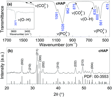
The XRD pattern of Ca–P–O gel powders annealed at 800 °C presented in Fig. 1, show that powders produced at 800 °C are already crystalline with well resolved diffraction peaks from the Bragg diffraction conditions for HAP [PDF# 00-3553] (hexagonal crystal system, space group of P63/m). In addition, Rietveld analysis was performed. The calculated lattice parameters (a = 9.4227(8) Å and c = 6.8843(6) Å) are consistent with the parameters found in literature for HAP.59 Rietveld refinement for XRD pattern (Fig. 2) showed the elongation of reflection at 2θ = 45.8° for (002) indicating possible elongation of crystals along the 〈002〉 plane. This agrees with our previous study where cHAP crystals produced from solutions containing polyethylene glycol exhibited slight lengthening compare to those produced from solutions containing polyvinyl alcohol.57 The average crystallite size was estimated to be 32 ± 5 nm. Small crystal sizes are linked to the relatively high solubility of biological apatites with respect to stoichiometric HAP,28 which probably alters the nanoscale surface structure, increasing the surface area and surface wettability of the scaffold, offering favourable conditions for cell adhesion.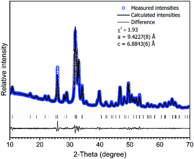 | ||
Fig. 2 Rietveld fit to cHAP powders XRD data. Experimental ( ) and calculated (–) patterns are shown along with the difference curve (–) and ( ) and calculated (–) patterns are shown along with the difference curve (–) and ( ) Bragg positions. ) Bragg positions. | ||
The FT-IR spectrum of cHAP calcined at 800 °C also shown in Fig. 1 shows the characteristic bands of phosphate (PO43−) and carbonate (CO32−) groups. The absorption bands between 1200 and 900 cm−1 are due to the triple degenerated asymmetric stretching mode ν3, and the symmetric stretching mode ν1 of the P–O bonds, while bands between 630 and 450 cm−1 are due to the triple degenerated bending mode ν4 of the O–P–O of apatitic PO43− groups. Bands in the 1550–1360 cm−1 region are characteristic of CO32− groups in the cHAP.57,60 The band at 875 cm−1 can be attributed to the CO32− group substituted for the PO43− group (type B carbonate apatite).61 Two distinctive peaks observed at 3571 and 630 cm−1 were assigned to the stretching mode νs and vibrational mode νL respectively of the structural hydroxyl anion (OH−) in cHAP. Carbonate ions can substitute a hydroxide (OH−) or phosphate (PO43−) group in the HAP (Ca10(PO4)6(OH)2) crystal lattice, leading respectively to A- or B-type carbonated apatites. Biological apatite is considered to be an AB carbonate-substituted apatite.28 Studies have shown that cHAP is more soluble in vivo than pure HAP,27,61 that it promote cell proliferation,62 and that it is therefore likely to lead to an increase in the biological response of the bone mineral while in contact with a cHAP-based scaffold.
Raman spectrum of cHAP powders annealed at 800 °C is presented in Fig. 3. Characteristic vibrations of the PO43− group appears in 1100–1000 cm−1 region and at 964 cm−1 (the most intense band), 587 cm−1 and 430 cm−1. These bands were attributed to the ν3(PO43−), ν1(PO43−), ν4(PO43−) and ν2(PO43−) modes, respectively.63–65 The carbonate band in the Raman spectrum appears at 1070 cm−1; it is quite week and overlaps with bands of the phosphate group (Fig. 3 (inset)).64 Furthermore, obtained small band at 326 cm−1 can be assigned to the ν4(Ca–OH) mode.65 Spectrum also shows the band located at 3572 cm−1 that was assigned to the stretching vibrations of the O–H group. The Raman spectrum agrees with the literature and the absence of a splitting in the most intense PO43− band indicates a homogeneous carbonate incorporation into the HAP lattice.
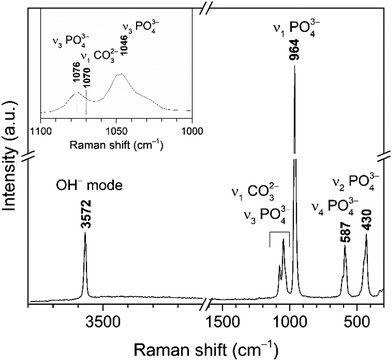 | ||
| Fig. 3 Raman spectrum of cHAP powders calcined at 800 °C (inset: enlarged spectrum region of overlapping bands assigned to PO43− and CO32− modes). | ||
3.2. Acrylate–gelatin–cHAP composite
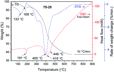
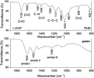
The wt% of cHAP and the distribution of apatite within the polymer matrix were evaluated by thermal analysis. TG, DTG and DSC curves of the acrylate(75%)–gelatin(25%)–cHAP composite are presented in Fig. 4, where the decomposition curves show four steps leaving about 37% residue at about 680 °C. The first weight loss of ∼2% was observed at temperatures up to 100 °C and was attributed to the evaporation of adsorbed water. A weight loss of ∼3% occurred upon further heating up to 200 °C with an exothermic peak at ∼191 °C. This loss was attributed to the initial degradation of the less thermally stable gelatin, as N-terminal residues are released before the complete separation as free amino acids, as well as polymer-bound water.66 The third and fourth overlapped steps represent a sequence of pyrolytic reactions. The first weight loss of ∼15% takes place at temperatures up to 400 °C and can be assigned to the partial decomposition of organic compounds (gelatin, acrylate) and the removal of CO2. Such processes are seen in the DTG curve where broad overlapping peaks with maxima at 320 and 400 °C occur. Heating to 650 °C led to a further 42% decrease in weight with a broad exothermic peak (max at 415 and 446 °C) and this was attributed to the decomposition of organic compounds, and to the removal of lattice water and carbonates from cHAP, as these processes occur at about 600 °C.63 The acrylate(50%)–gelatin(50%)–cHAP and acrylate(95%)–gelatin(5%)–cHAP composites exhibited similar decomposition behaviour (data not presented).The presence of prominent components within the multi-composite scaffolds was confirmed by FTIR spectroscopy, where the IR spectrum of the representative acrylate(75%)–gelatin(25%)–cHAP composite scaffold shown in Fig. 5 exhibits characteristic bands assigned to acrylate, cHAP and gelatin. The absorption bands at 1089, 1024, 962 and 629 cm−1 were assigned to the cHAP. The spectral features of the apatite do not appear to have changed after it was incorporated into the polymeric matrix. The spectrum of the multi-composite also shows a wide band in the 1730–1700 cm−1 region which can be ascribed to the carbonyl (C![[double bond, length as m-dash]](https://www.rsc.org/images/entities/char_e001.gif) O) group stretching vibrations of acrylate.67,68 The important peaks for C
O) group stretching vibrations of acrylate.67,68 The important peaks for C![[double bond, length as m-dash]](https://www.rsc.org/images/entities/char_e001.gif) C deformation of the acrylate group appear at 1636, 1408 and 809 cm−1, and this indicates that some residual C
C deformation of the acrylate group appear at 1636, 1408 and 809 cm−1, and this indicates that some residual C![[double bond, length as m-dash]](https://www.rsc.org/images/entities/char_e001.gif) C bonds remain inside the network structure. The copolymerization of DPHA and EGDMA monomers under UV irradiation is a free radical chain growth cross-linking reaction that is diffusion-controlled. The molar ratios of C
C bonds remain inside the network structure. The copolymerization of DPHA and EGDMA monomers under UV irradiation is a free radical chain growth cross-linking reaction that is diffusion-controlled. The molar ratios of C![[double bond, length as m-dash]](https://www.rsc.org/images/entities/char_e001.gif) C bonds in the different monomers, the concentration of initiator, the curing times, and the reaction temperatures affect the reaction kinetics and products. Although the formation of a cross-linked structure reduces the termination rate of free radicals, it also reduces the diffusion of reactants in the later stages of the reaction, so the final conversion is limited.69 The relative intensities of the 1636 cm−1 (C
C bonds in the different monomers, the concentration of initiator, the curing times, and the reaction temperatures affect the reaction kinetics and products. Although the formation of a cross-linked structure reduces the termination rate of free radicals, it also reduces the diffusion of reactants in the later stages of the reaction, so the final conversion is limited.69 The relative intensities of the 1636 cm−1 (C![[double bond, length as m-dash]](https://www.rsc.org/images/entities/char_e001.gif) C stretching) and 1723 cm−1 (C
C stretching) and 1723 cm−1 (C![[double bond, length as m-dash]](https://www.rsc.org/images/entities/char_e001.gif) O stretching) peaks nevertheless indicate that the monomers were consumed during curing and that a highly crosslinked network was created. The simplified intermolecular cross-linking of monomers DPHA and EGDMA under UV irradiation is shown in Fig. 6.
O stretching) peaks nevertheless indicate that the monomers were consumed during curing and that a highly crosslinked network was created. The simplified intermolecular cross-linking of monomers DPHA and EGDMA under UV irradiation is shown in Fig. 6.
Furthermore, the spectrum of pure gelatin in Fig. 5 exhibits absorption bands in the 1700–1600, 1565–1520 and 1280–1230 cm−1 regions, and these are characteristic vibrations arising from amide I, amide II and amide III, respectively.70 It can be seen that the bands attributed to amide I and amide II exhibit different spectral features in the spectrum of the multi-composite scaffold, and that the broad band of amide III is absent, indicating some structural changes. Similar spectral features were observed in a related study where the interactions of calcium phosphate as an inorganic phase within an organic matrix were studied.71,72
Several other peaks in the spectrum of the composite can be observed at ∼1460 cm−1 attributed to the C–H vibrations, while broad bands at 1265 cm−1 and 1180 cm−1 are due to C–O–C stretching moieties of the acrylate.73
3.3. Surface morphology
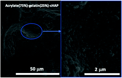
Fig. 7 shows FE-SEM images of a representative acrylate(75%)–gelatin(25%)–cHAP composite that on a macroscale (left) the composite surface is rather uneven, but a higher magnification (right) shows that the cHAP particles are homogeneously imbedded in the continuous polymeric matrix. Voids and large agglomerate blocks were also observed on parts of the composite pellets. The cHAP–acrylate(50%)–gelatin(50%) composites exhibited a slightly rougher surface, possibly due to the higher cHAP concentration. Fig. 8 shows SEM images and corresponding EDS spectra of the multi-composites. The 50/50 composite shows voids with a width of 300 μm. Elements C, O, P and Ca were detected. Al and Ag were also detected, but these were due to the sample holder and pre-sputtering, respectively. The average atomic% ratio of Ca/P was calculated to be 1.6 (n = 11) and place dependency was revealed. In the nonstoichiometric apatites, the Ca/P ratio depends on the ionic substitution in the crystal lattice. That is, when PO43− ions are replaced by CO32− ions (B-substitution), the Ca/P ratio is larger than that of stoichiometric HAP, and when OH− ions in the apatite structure are replaced by CO32− ions (A-type substitution) or HPO43− ions replace PO43− the Ca/P ratio tends to be smaller than 1.67.57,74 Other composites exhibited similar morphological features.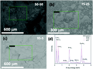 | ||
| Fig. 8 (a–c) SEM images (marked places show the surface regions examined) and (d) EDS spectra of acrylate–gelatin–cHAP composite scaffolds. | ||
3.4. Computed tomography (CT)
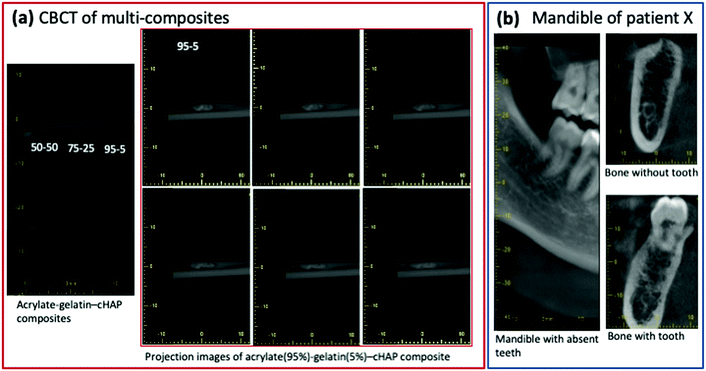
Computed tomography (CT) was used to assess the density of the scaffolds. The cross-sectional CT images of acrylate–gelatin–cHAP scaffolds (scan performed at 80 kV) presented in Fig. 9 (inset: camera photos of scaffolds) shows that the scaffolds with different compositions had different densities. The average density was calculated to be 1863, 2171 and 2224 kg m−3 for the 50/50, 75/25 and 95/5 composite scaffolds, respectively. The difference in density is mainly due to a difference in material composition, but the density varied slightly within the specimen, the material density being higher in the central region than in the outer layer. The density values of the multi-composites were not changed when scan was performed at 110 kV. A number of bone-scaffold features affect scaffold resorption, cell penetration and the ingrowth of new bone.75–77 Since the porosity of the material is related to its density, the rate of dissolution of surface components, the formation of voids within the scaffold, and the penetration of liquid phase into the inner layers of the composite can be predicted. Thus, the 50/50 multi-composite scaffolds probably have the fastest degradation and the greatest formation of voids within the scaffold when it is in contact with a liquid phase. Due to the higher atomic numbers of the elements, the ceramic material attenuates the X-ray beam more than the acrylate/gelatin matrix, but the internal microstructure of the composites was not resolved due to the lower resolution of the medical CT scanner compared to that of other (micro- and nano-) CT devices.78 Extensive studies have demonstrated the micro-CT can reveal bone tissue density as well as new bone formation throughout the depth of the scaffolds,51–53,79 although the use of contrast agents or a complementary technique such as MRI may be needed.80To obtain more complete characterization in assessing inner architecture of scaffolds, a cone beam computed tomography (CBCT) analysis was performed. Fig. 10(a) shows CBCT image of 50/50, 75/25 and 95/5 composites as well as segmented images (6 of total 24) of multiple projections of the 95/5 composite. Data demonstrate that radiographic contrast of the images is higher. Composite, although mostly radiolucent, it also contains apatite particles that are radiopaque. Some fogging in the images of the composites is also present and this was attributed to the scattered X-ray radiation. To compare a subject contrast, the mandible (lower jaw) images of patient X are presented in Fig. 10(b). These intraoral CBCT images were taken under the same conditions as fabricated scaffolds. Comparison of images show that dental bone exhibits higher contrast indicating that fabricated multi-composites could be more easily distinguished after the implantation while observing anatomic structures of interest.
3.5. Conventional radiography
To further evaluate structural features of the scaffolds, conventional dental radiography was used, as shown in Fig. 11 which presents a radiographic image of a representative acrylate(75%)–gelatin(25%)–cHAP scaffold. Composite is as a restorative material and their radiographic appearance vary depending on their thickness, density, and atomic number. Due to its higher radiological density compared to that of the organic matrix, the apatitic phase is clearly visible with a homogeneous distribution of the cHAP over the entire scaffold. This indicates the possibilities of achieving radiographic differentiation between the bone tissue and the restorative scaffold and of evaluating structural changes when it is replaced by de novo bone.81,82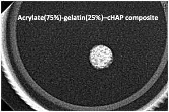 | ||
| Fig. 11 X-ray radiograph of the representative acrylate(75%)–gelatin(25%)–cHAP composite scaffold showing the distribution of cHAP (brighter places) within the organic matrix. | ||
3.6. Surface hydrophilicity
The wettability of the scaffolds was assessed by measuring the contact angle of water tinted with methylene blue dye which is frequently used as a cationic stain to examine cytological specimens.35,82 The sessile drop contact angles are presented as function of time in Fig. 12. Within a few seconds, the contact angle on all the scaffolds decreased by 15–20° (initial average angles of 91°, 100° and 67° were measured for the 50/50, 75/25 and 95/5 composites, respectively) (n = 3). The angle then gradually decreased more slowly until it reached a plateau. The final values after 60 seconds were 47.6° and 31.4° for the 50/50 and 95/5 composites, respectively. The 75/5 composite however exhibited a slightly different behaviour. After the initial decrease, the contact angle decreased relatively rapidly from 63.4° to 21.5° (within 15 s) and then continued to decline until the final angle after 50 seconds was found to be 16.6°, indicating that this was the most hydrophilic surface investigated. These differences in the contact angle were attributed to differences in surface morphology (Fig. 7 and 8) which depend on the composition. The surface characteristics, such as the porosity (pore diameter, interconnectedness, pore orientation), roughness and topography as well as chemistry (element present, presence of polar/non-polar group, acid–base characteristics, dangling bonds), have a great effect on the hydrophilicity and subsequently bioactivity.83,84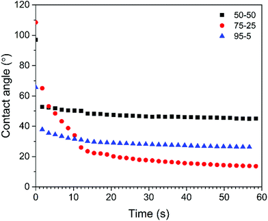 | ||
| Fig. 12 Contact angles vs. time (sessile drop of water tinted with methylene blue dye) on acrylate–gelatin–cHAP composite scaffolds (values of the first measurement are presented). | ||
The rates of degradation of DPHA, EGDMA and gelatin differ, and the combination of DPHA/EGDMA, gelatin and cHAP in bone tissue engineering can therefore provide some advantages, as the composites may degrade faster than a pure acrylate-based polymer matrix. The hydrophilicity of the bioceramic and gelatin should enable water to penetrate more easier into the acrylate-based matrix and thus promote hydrolytic degradation where scaffolds and body fluids interact, and the microstructural architecture of the scaffold could enhance the mineralization of new bone in the interior of the composite material and allow deeper tissue ingrowth.
The favourable properties of the acrylate–gelatin–cHAP composites made by the approach described here may extend the potential for porosity as well as hydrophilicity remodelling, and promote scaffold-implant integration. These applications are presently under investigation.
4. Conclusions
In this work, carbonated hydroxyapatite (cHAP) was synthesized by precipitation and annealing at 800 °C. XRD analysis showed that the cHAP powders were a phase pure, having a crystallite size of 32 nm. FTIR studies confirmed that AB-substituted cHAP was synthesized. Raman studies and Rietveld analysis revealed the homogeneous carbonate substitution throughout the HAP lattice. Multi-composites consisting of acrylate (DPHA/EGDMA), cHAP and gelatin were successfully prepared via copolymerization. Morphological studies revealed that cHAP particles were homogeneously imbedded within the continuous polymeric matrix, and that the scaffolds possessed voids and large agglomerate blocks in different parts of the composite pellets. TG analysis confirmed that the residual inorganic material mass corresponded well with the initial quantity of cHAP. CT analysis showed that the scaffolds had differing average densities and that the scaffolds had a higher density in the central region than in the outer layer. CBCT analysis revealed that dental bone exhibits higher radiographic contrast than fabricated multi-composites, and so indicate easier identification after the implantation while observing anatomic structures of interest. Conventional radiography images further validated cHAP, exhibiting higher radiographic density compared to organic matrix, and homogeneous distribution within the entire scaffold. Contact angle measurements revealed that the hydrophilicity was composition- and morphology-dependent, the greatest wettability of 16.6° being on the acrylate(75%)–gelatin(25%)–cHAP composite scaffold. The favourable properties of the composites fabricated using the approach described here may have potential in porosity and hydrophilicity remodelling strategies, and subsequently promote scaffold-implant integration.Conflicts of interest
There are no conflicts to declare.Acknowledgements
The computed tomography studies using a CT-scanner (Siemens Somatom Emotion Duo) were supported by FORMAS grant (No. 2018-01198). Dr Ramunas Skaudzius is acknowledged for helping with Rietveld analysis.References
- Global data: Dental Bone Grafts & Substitutes Market Analysis Report by Material Type (Allograft, Xenograft, Synthetic), by Application (Sinus Lift, Ridge Augmentation), by End Use (Hospitals, Dental Clinics), and Segment Forecast, 2019-2026; Publisher: Grand View Research (SKU: GV16142504), 2019, December, Retrieved from: https://www.marketresearch.com/Grand-View-Research-v4060/Dental-Bone-Grafts-Substitutes-Material-12964345/.
- L. Polo-Corrales, M. Latorre-Esteves and J. E. Ramirez-Vick, Nanosci. Nanotechnol., 2014, 14, 15–56 CrossRef CAS.
- L.-P. Yan, J. M. Oliveira, A. L. Oliveira and R. L. Reis, ACS Biomater. Sci. Eng., 2015, 1, 183–200 CrossRef CAS.
- M. M. Stevens, Mater. Today, 2008, 11, 18–25 CrossRef CAS.
- K. Rezwan, Q. Z. Chen, J. J. Blaker and A. R. Boccaccini, Biomaterials, 2006, 27, 3413–3431 CrossRef CAS.
- Y. Du, J. L. Guo, J. Wang, A. G. Mikos and S. Zhang, Biomaterials, 2019, 218, 119334 CrossRef CAS.
- B. Conrad, C. Hayashi and F. Yang, ACS Biomater. Sci. Eng., 2020, 6, 3454–3463 CrossRef CAS.
- G. Fernandez de Grado, L. Keller, Y. Idoux-Gillet, Q. Wagner, A.-M. Musset, N. Benkirane-Jessel, F. Bornert and D. Offner, J. Tissue Eng., 2018, 9, 1–18 Search PubMed.
- A. R. Amini, C. T. Laurencin and S. P. Nukavarapu, Crit. Rev. Biomed. Eng., 2012, 40, 363–408 CrossRef.
- E. García-Gareta, M. J. Coathup and G. W. Blunn, Bone, 2015, 81, 112–121 CrossRef.
- H. J. Haugen, S. P. Lyngstadaas, F. Rossi and G. Perale, J. Clin. Periodontol., 2019, 46, 92–102 CrossRef.
- Z. Hao, Z. Song, J. Huang, K. Huang, A. Panetta, Z. Gu and J. Wu, Biomater. Sci., 2017, 5, 1382–1392 RSC.
- G. Narayanan, V. N. Vernekar, E. L. Kuyinu and C. T. Laurencin, Adv. Drug Delivery Rev., 2016, 107, 247–276 CrossRef CAS.
- Y. Jung, M. S. Park, J. W. Lee, Y. H. Kim, S.-H. Kim and S. H. Kim, Biomaterials, 2008, 29, 4630–4636 CrossRef CAS.
- J. Zhang, S. Yang, X. Yang, Z. Xi, L. Zhao, L. Cen, E. Lu and Y. Yang, ACS Biomater. Sci. Eng., 2018, 4, 694–706 CrossRef CAS.
- A. Fottner, B. Nies, D. Kitanovic, A. Steinbrück, S. Mayer-Wagner, C. Schröder, S. Heinemann, U. Pohl and V. Jansson, J. Mater. Sci.: Mater. Med., 2016, 27, 138 CrossRef.
- J. C. J. Webb and R. F. Spencer, J. Bone Jt. Surg., Br. Vol., 2007, 89B, 851–857 CrossRef.
- P. Gentile, V. Chiono, I. Carmagnola and P. V. Hatton, Int. J. Mol. Sci., 2014, 15, 3640–3659 CrossRef CAS.
- J. J. Chung, S. Li, M. M. Stevens, T. K. Georgiou and J. R. Jones, Chem. Mater., 2016, 28, 6127–6135 CrossRef CAS.
- F. Donnaloja, E. Jacchetti, M. Soncini and T. M. Raimondi, Polymers, 2020, 12, 905–932 CrossRef CAS.
- R. Zhang and P. X. Ma, J. Biomed. Mater. Res., 1999, 45, 285–293 CrossRef CAS.
- J. E. Devin, M. A. Attawia and C. T. Laurencin, J. Biomater. Sci., Polym. Ed., 1996, 7, 661–669 CrossRef CAS.
- K. Yoshihara, N. Nagaoka, S. Hayakawa, T. Okihara, Y. Yoshida and B. Van Meerbeek, Dent. Mater., 2018, 34, 1072–1081 CrossRef CAS.
- S. E. Lobo and T. L. Arinzeh, Materials, 2010, 3, 815–826 CrossRef CAS.
- R. Z. LeGeros, S. Lin, R. Rohanizadeh, D. Mijares and J. P. LeGeros, J. Mater. Sci.: Mater. Med., 2003, 14, 201–209 CrossRef CAS.
- G. Wang, Z. Lu, X. Zhao, A. Kondyurin and H. Zreiqat, J. Mater. Chem. B, 2013, 1, 2455–2462 RSC.
- Y. Doi, T. Shibutani, Y. Moriwaki, T. Kajimoto and Y. Iwayama, J. Biomed. Mater. Res., 1998, 39, 603–610 CrossRef CAS.
- E. Boanini, M. Gazzano and A. Bigi, Acta Biomater., 2010, 6, 1882–1894 CrossRef CAS.
- H. H. Xu and C. G. Simon, Jr., J. Biomed. Mater. Res., Part A, 2004, 69, 267–278 CrossRef.
- H. Shen, X. Hu, F. Yang, J. Bei and S. Wang, Biomaterials, 2007, 28, 4219–4230 CrossRef CAS.
- L. Zhu, D. Luo and Y. Liu, Int. J. Oral Sci., 2020, 12, 6 CrossRef CAS.
- M. Costantini and A. Barbetta, in Functional 3D Tissue Engineering Scaffolds, ed. Y. Deng and J. Kuiper, Woodhead Publishing, 2018, pp. 127–149 DOI:10.1016/B978-0-08-100979-6.00006-9.
- W. Chen, H. Zhou, M. Tang, M. D. Weir, C. Bao and H. H. K. Xu, Tissue Eng., Part A, 2012, 18, 816–827 CrossRef CAS.
- S. Hesaraki, F. Moztarzadeh and D. Sharifi, J. Biomed. Mater. Res., Part A, 2007, 83, 80–87 CrossRef CAS.
- P. Habibovic, H. Yuan, C. M. van der Valk, G. Meijer, C. A. van Blitterswijk and K. de Groot, Biomaterials, 2005, 26, 3565–3575 CrossRef CAS.
- A. Barbetta, M. Dentini, E. M. Zannoni and M. E. De Stefano, Langmuir, 2005, 21, 12333–12341 CrossRef CAS.
- M. Schardosim, J. Soulié, D. Poquillon, S. Cazalbou, B. Duployer, C. Tenailleau, C. Rey, R. Hübler and C. Combes, Mater. Sci. Eng., C, 2017, 77, 731–738 CrossRef CAS.
- A. Lee, C. R. Langford, L. M. Rodriguez-Lorenzo, H. Thissen and N. R. Cameron, Biomater. Sci., 2017, 5, 2035–2047 RSC.
- I. K. Januariyasa, I. D. Ana and Y. Yusuf, Mater. Sci. Eng., C, 2020, 107, 110347 CrossRef CAS.
- I. Gendviliene, E. Simoliunas, S. Rekstyte, M. Malinauskas, L. Zaleckas, D. Jegelevicius, V. Bukelskiene and V. Rutkunas, J. Mech. Behav. Biomed. Mater., 2020, 104, 103616 CrossRef CAS.
- J. Lee and G. Kim, ACS Biomater. Sci. Eng., 2018, 4, 278–289 CrossRef CAS.
- Y. Luo, Y. Li, X. Qin and Q. Wa, Mater. Des., 2018, 146, 12–19 CrossRef CAS.
- C. Shuai, B. Yang, S. Peng and Z. Li, Int. J. Adv. Des. Manuf. Technol., 2013, 69, 51–57 CrossRef.
- D. Miranda-Nieves and E. L. Chaikof, ACS Biomater. Sci. Eng., 2017, 3, 694–711 CrossRef CAS.
- P. Zhai, X. Peng, B. Li, Y. Liu, H. Sun and X. Li, Int. J. Biol. Macromol., 2020, 151, 1224–1239 CrossRef CAS.
- A. M. Ferreira, P. Gentile, V. Chiono and G. Ciardelli, Acta Biomater., 2012, 8, 3191–3200 CrossRef CAS.
- S. Ber, G. Torun Köse and V. Hasırcı, Biomaterials, 2005, 26, 1977–1986 CrossRef CAS.
- P. S. Kowalski, C. Bhattacharya, S. Afewerki and R. Langer, ACS Biomater. Sci. Eng., 2018, 4, 3809–3817 CrossRef CAS.
- M. C. Gómez-Guillén, B. Giménez, M. E. López-Caballero and M. P. Montero, Food Hydrocoll., 2011, 25, 1813–1827 CrossRef.
- A. K. Teotia, A. Gupta, D. B. Raina, L. Lidgren and A. Kumar, ACS Appl. Mater. Interfaces, 2016, 8, 10775–10787 CrossRef CAS.
- M. Mashiatulla, R. D. Ross and D. R. Sumner, Bone, 2017, 99, 53–61 CrossRef.
- J. R. Jones, G. Poologasundarampillai, R. C. Atwood, D. Bernard and P. D. Lee, Biomaterials, 2007, 28, 1404–1413 CrossRef CAS.
- A. C. Jones, C. H. Arns, A. P. Sheppard, D. W. Hutmacher, B. K. Milthorpe and M. A. Knackstedt, Biomaterials, 2007, 28, 2491–2504 CrossRef CAS.
- A. J. Wagoner Johnson and B. A. Herschler, Acta Biomater., 2011, 7, 16–30 CrossRef CAS.
- S. Weiner and H. D. Wagner, Annu. Rev. Mater. Sci., 1998, 28, 271–298 CrossRef CAS.
- G. J. Kazakia, A. J. Burghardt, S. Cheung and S. Majumdar, Med. Phys., 2008, 35, 3170–3179 CrossRef CAS.
- E. Garskaite, L. Alinauskas, M. Drienovsky, J. Krajcovic, R. Cicka, M. Palcut, L. Jonusauskas, M. Malinauskas, Z. Stankeviciute and A. Kareiva, RSC Adv., 2016, 6, 72733–72743 RSC.
- W. Huda, E. M. Scalzetti and G. Levin, Radiology, 2000, 217, 430–435 CrossRef CAS.
- M. Jevtić, M. Mitrić, S. Škapin, B. Jančar, N. Ignjatović and D. Uskoković, Cryst. Growth Des., 2008, 8, 2217–2222 CrossRef.
- R. Golubevas, A. Zarkov, L. Alinauskas, Z. Stankeviciute, G. Balciunas, E. Garskaite and A. Kareiva, RSC Adv., 2017, 7, 33558–33567 RSC.
- M. Hasegawa, Y. Doi and A. Uchida, J. Bone Jt. Surg., Br. Vol., 2003, 85-B, 142–147 CrossRef.
- M.-M. Germaini, R. Detsch, A. Grünewald, A. Magnaudeix, F. Lalloue, A. R. Boccaccini and E. Champion, Biomed. Mater., 2017, 12, 035008 CrossRef.
- E. Garskaite, K.-A. Gross, S.-W. Yang, T. C.-K. Yang, J.-C. Yang and A. Kareiva, CrystEngComm, 2014, 16, 3950–3959 RSC.
- F. F. de Mul, M. H. Hottenhuis, P. Bouter, J. Greve, J. Arends and J. J. ten Bosch, J. Dent. Res., 1986, 65, 437–440 CrossRef CAS.
- M. P. M. Marques, A. P. Mamede, A. R. Vassalo, C. Makhoul, E. Cunha, D. Gonçalves, S. F. Parker and L. A. E. Batista de Carvalho, Sci. Rep., 2018, 8, 15935 CrossRef CAS.
- A. A. Apostolov, S. Fakirov, E. Vassileva, R. D. Patil and J. E. Mark, J. Appl. Polym. Sci., 1999, 71, 465–470 CrossRef CAS.
- A. Tuncel and E. Pişkin, J. Appl. Polym. Sci., 1996, 62, 789–798 CrossRef CAS.
- M. U. Minhas, M. Ahmad, J. Anwar and S. Khan, Adv. Polym. Technol., 2018, 37, 221–229 CrossRef CAS.
- C.-W. Huang, Y.-M. Sun and W.-F. Huang, J. Polym. Sci., Part A: Polym. Chem., 1997, 35, 1873–1889 CrossRef CAS.
- N. Cebi, M. Z. Durak, O. S. Toker, O. Sagdic and M. Arici, Food Chem., 2016, 190, 1109–1115 CrossRef CAS.
- R. W. Arcís, A. López-Macipe, M. Toledano, E. Osorio, R. Rodríguez-Clemente, J. Murtra, M. A. Fanovich and C. D. Pascual, Dent. Mater., 2002, 18, 49–57 CrossRef.
- S. W. Xu, J. P. Zheng, L. Tong and K. D. Yao, J. Appl. Polym. Sci., 2006, 101, 1556–1561 CrossRef CAS.
- H. A. Willis, V. J. I. Zichy and P. J. Hendra, Polymer, 1969, 10, 737–746 CrossRef CAS.
- A. Yasukawa, K. Kandori and T. Ishikawa, Calcif. Tissue Int., 2003, 72, 243–250 CrossRef CAS.
- P. S. P. Poh, D. Valainis, K. Bhattacharya, M. van Griensven and P. Dondl, Sci. Rep., 2019, 9, 9170 CrossRef.
- A. Cipitria, C. Lange, H. Schell, W. Wagermaier, J. C. Reichert, D. W. Hutmacher, P. Fratzl and G. N. Duda, J. Bone Miner. Res., 2012, 27, 1275–1288 CrossRef CAS.
- A. Petersen, A. Princ, G. Korus, A. Ellinghaus, H. Leemhuis, A. Herrera, A. Klaumünzer, S. Schreivogel, A. Woloszyk, K. Schmidt-Bleek, S. Geissler, I. Heschel and G. N. Duda, Nat. Commun., 2018, 9, 4430 CrossRef CAS.
- M. Kampschulte, A. C. Langheinirch, J. Sender, H. D. Litzlbauer, U. Althohn, J. D. Schwab, E. Alejandre-Lafont, G. Martels and G. A. Krombach, Rofo-Fortschr. Rontg., 2016, 188, 146–154 CrossRef CAS.
- L. Borkowski, A. Sroka-Bartnicka, I. Polkowska, M. Pawlowska, K. Palka, E. Zieba, A. Slosarczyk, K. Jozwiak and G. Ginalska, Anal. Bioanal. Chem., 2017, 409, 5747–5755 CrossRef CAS.
- K. D. Novakofski, S. L. Pownder, M. F. Koff, R. M. Williams, H. G. Potter and L. A. Fortier, Cartilage, 2016, 7, 39–51 CrossRef CAS.
- N. A. Kotnis, N. Parasu, K. Finlay, E. Jurriaans and M. Ghert, Skeletal Radiol., 2011, 40, 563–570 CrossRef.
- R. Duan, D. Barbieri, F. de Groot, J. D. de Bruijn and H. Yuan, ACS Biomater. Sci. Eng., 2018, 4, 3347–3355 CrossRef CAS.
- V. Karageorgiou and D. Kaplan, Biomaterials, 2005, 26, 5474–5491 CrossRef CAS.
- M. J. Dalby, L. Di Silvio, E. J. Harper and W. Bonfield, Biomaterials, 2002, 23, 569–576 CrossRef CAS.
| This journal is © The Royal Society of Chemistry 2020 |

