A new aluminium-ion battery with high voltage, high safety and low cost†
Haobo
Sun
,
Wei
Wang
,
Zhijing
Yu
,
Yan
Yuan
,
Shuai
Wang
and
Shuqiang
Jiao
*
State Key Laboratory of Advanced Metallurgy, University of Science and Technology Beijing, Beijing 100083, P. R. China. E-mail: sjiao@ustb.edu.cn
First published on 16th June 2015
Abstract
A new kind of Al-ion battery with carbon paper as the cathode, high-purity Al foil as the anode and ionic liquid as the electrolyte is proposed in this work. The significance of the presented battery is going to be an extremely high average voltage plateau of ca. 1.8 V vs. Al3+/Al.
Li-ion batteries have been extensively investigated due to their excellent energy and power density. However, their disadvantages are obvious, including cost, lithium resource, reliability, and safety.1–4 Owing to the natural abundance and low cost of aluminium, Al-based batteries have become one of the candidates for energy storage devices.5–11 The Al–air battery system has been investigated for years; however, due to the fast corrosion and hydrogen evolution reaction between aluminium and the electrolyte, the utilization of the electrode is reduced, even leading to the scrappage of the battery.12–15 Recently, an Al-ion battery with multivalent metal ions transmitting internally has attracted much attention, such as VO2,5 V2O5,6 anatase TiO2 in aqueous solution,7 fluorinated natural graphite,8 polymers,9 copper hexacyanoferrate,10 and prussian blue analogs.11 However, none of them is satisfactory for their low capacity, low voltage plateau or short cycle life. We established a new kind of Al-ion battery with high average voltage plateau and proposed a new theory—“multi-coordination ion/single ion intercalation and deintercalation”.
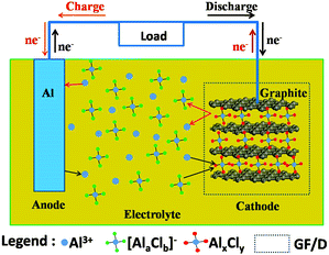
The detailed experimental methods are shown in the ESI.† The main idea of an Al-ion battery is described in Fig. 1. The corresponding experimental photographs are also displayed in Fig. S1a–e (ESI†). All electrochemical reactions occur in the sealed Teflon electrolytic tank. In our device, aluminium foil serves as anode material. At the same time, carbon paper (Fig. 4(d) shows that it is composed of graphite) serves as cathode material. Conventional Li-ion and Na-ion batteries can only transfer one charge in one redox couple (Li+/Li or Na+/Na), while Al-ion batteries can transfer three charges in one redox couple (Al3+/Al), which can achieve more gravimetric capacity and volumetric capacity than Li-ion and Na-ion batteries.5,6,16 The electrolyte is the mixture of AlCl3 and 1-ethyl-3-methylimidazolium chloride ([EMIm]Cl) with a 1.3![[thin space (1/6-em)]](https://www.rsc.org/images/entities/char_2009.gif) :
:![[thin space (1/6-em)]](https://www.rsc.org/images/entities/char_2009.gif) 1 molar ratio. In the discharge process, Al metal is oxidized and escapes from Al foil to form Al3+. Under the influence of the electric field, Al ions move to the cathode side. Then Al ions and aluminium chloride coordination anions ([AlaClb]−) simultaneously intercalate into the graphite layers, forming AlxCly. The intercalated AlxCly and neighboring graphite layers interact with each other by van der Waals' forces. While in the charge process, the electrochemical reactions are just the opposite. In the as-prepared ionic liquid, the coordination ions existed are AlCl4− or Al2Cl7−,17 so the intercalated coordination ion [AlaClb]− might be AlCl4− or Al2Cl7− or a mixture of them. There should be concentration equilibrium between Al3+, AlCl4− and Al2Cl7− in the electrolyte to maintain the intercalation and deintercalation process, which needs to be further studied. Based on the above assumption, the electrode reactions for both anode and cathode could be described as follows:
1 molar ratio. In the discharge process, Al metal is oxidized and escapes from Al foil to form Al3+. Under the influence of the electric field, Al ions move to the cathode side. Then Al ions and aluminium chloride coordination anions ([AlaClb]−) simultaneously intercalate into the graphite layers, forming AlxCly. The intercalated AlxCly and neighboring graphite layers interact with each other by van der Waals' forces. While in the charge process, the electrochemical reactions are just the opposite. In the as-prepared ionic liquid, the coordination ions existed are AlCl4− or Al2Cl7−,17 so the intercalated coordination ion [AlaClb]− might be AlCl4− or Al2Cl7− or a mixture of them. There should be concentration equilibrium between Al3+, AlCl4− and Al2Cl7− in the electrolyte to maintain the intercalation and deintercalation process, which needs to be further studied. Based on the above assumption, the electrode reactions for both anode and cathode could be described as follows:
 | ||
| Fig. 1 Schematic representation of an aluminium-based full-battery system during the charge and discharge process. | ||
In the charge process,
| Al3+ + 3e− → Al (anode) | (1) |
| AlxCly − e− → Al3+ + [AlaClb]− (cathode) | (2) |
| Al − 3e− → Al3+ (anode) | (3) |
| Al3+ + [AlaClb]− + e− → AlxCly (cathode) | (4) |
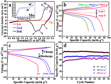
Fig. 2(a) shows the CV curve of an Al-ion battery for the initial three cycles. It should be mentioned that before the batteries are tested, we let them sit overnight. The initial CV curve differs from the other curves, which could be attributed to the volume adjustment of the graphite in the initial cycle and some side reactions, making the graphite layers more suitable for the intercalation and deintercalation of coordination ions. The second and third curves exactly coincide with each other, demonstrating a highly reversible electrochemical reaction. Three obvious reduction peaks can be seen at ca. 1.65 V (a peak), 1.77 V (b peak) and 2.0 V (c peak), respectively. Also, the corresponding oxidation peaks are found at 2.10 V (a′ peak), 2.24 V (b′ peak) and 2.34 V (c′ peak), respectively. The polarization voltage of this battery could be mainly caused by the following reasons: (1) the ionic diameter of Al ions and coordination ions is fairly large, which could inhibit the diffusion of these ions in the electrolyte and the intercalation and deintercalation in the graphite layers and (2) the passivation film of Al foil in the anode side may also restrain the deposition and dissolution of Al. To study the influence of the Mo current collector and the electrochemical reactions of the electrolyte, the CV image of Mo is shown in Fig. 2(a). When compared with the battery, the CV curve of Mo is nearly straight. To see it more clearly, the CV curve of Mo is magnified in the inset. Obvious redox peaks at 1.73 V and 1.85 V can be seen, which agrees well with that of the battery. It can be deduced that similar redox reactions occur on the interface of both Mo and C electrodes. Whereas the current density of graphite is hundreds of times that of Mo, and hence, the influence of Mo in this battery system can be ignored. In other words, the redox reaction only occurs at the interface of the graphite–electrolyte.
Fig. 2(b) shows the charge and discharge curves under different current densities from 50 mA g−1 to 150 mA g−1. The cut-off voltages were set in the range of 0.4–2.35 V vs. Al3+/Al. Both charge and discharge voltage plateaus can be seen obviously and the average voltage plateau for the discharge process is as high as ca. 1.8 V vs. Al3+/Al. This is the first time that such a high voltage plateau has been reported, which exhibits high energy density and promising brilliant commercial application prospect.
The 1st, 50th and 100th charge–discharge curves at 100 mA g−1 are shown in Fig. 2(c). It is worth mentioning that due to the low cost and durability of aluminium foil, excess anode material is used to allow full play to the cathode, so the specific capacity and current density of the Al-ion battery were calculated based on the mass of the carbon paper. Even after 100 cycles, the charge and discharge curves deliver a discharge capacity of 69.92 mA h g−1, which shows an excellent capacity performance. Considering the high voltage and large charge and discharge current density, this battery exhibits high energy and power density. The charge and discharge curves of different cycles are very similar, demonstrating a highly reversible reaction. The cycle performances of the battery under different current densities over 50 cycles are displayed in Fig. 2(d). Excellent cycle performance as well as high capacity has been achieved. At the current density of 50 mA g−1, the discharge capacity is 84.55 mA h g−1 over 50 cycles. Even at a high current density of 150 mA g−1, the discharge capacity still remains 62.71 mA h g−1 over 50 cycles. The cycle performance and coulombic efficiency of the Al-ion battery at 100 mA g−1 over 100 cycles are shown in Fig. S2 (ESI†). In the initial three cycles, the charge and discharge capacity is a little unstable. While three cycles later, the capacity basically remains stable. The corresponding coulombic efficiency is steady, and after three cycles, it is almost near 100%.
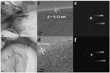
Fig. 3(a) and (b) show the TEM images of original carbon paper and cycled one. Ultrathin crumpled nanosheets with hundreds of nanometers in diameter can be seen clearly. Despite undergoing 100 charge and discharge cycles, nearly no difference can be observed on the surface of the carbon paper. However, if taken a close view, things are quite different, as shown in Fig. 3(c) and (d). The distance of the adjacent graphitic layers is about 0.33 nm, which is the characteristic of crystalline graphite. However, after 100 cycles, the neighboring graphite intercalating space of the discharged carbon paper is greatly enlarged, that is ca. 0.455 nm. These could also be observed visually in Fig. S1d (ESI†). After 100 cycles, the volume of the carbon paper expands dramatically compared to the original, which agrees with the analysis of HRTEM. Meanwhile, the morphology of the surface still remains unchanged. The corresponding SAED images of the original and cycled carbon paper are displayed in Fig. 3(e) and (f), both of which are similar and demonstrate the characteristic of crystalline graphite. From the above description, we can summarize as follows: (1) the crumpled nanosheets provide a large surface area, which is beneficial for the sufficient contact between the active material and the liquid electrolyte,18–22 (2) during the charge and discharge process, the electrochemical reaction takes place only in the interlayer of graphite, and the surface of the graphite does not involve in the reaction (3) due to the good crystallization, the structure of graphite remains stable even after tens of cycles, which can improve the cycle life (4) considering the dramatically increased neighboring graphite intercalating space, the intercalated ions might involve big coordination ions, not only single Al3+ (small ionic radius). To research the charge and discharge process meticulously, we prepared a series of cathode produces through a charge–discharge cycle. Fig. S3 (ESI†) shows HRTEM images of the products after charge (a, b) and discharge (c, d) processes. As shown in Fig. S3 (ESI†), from the charge process to the discharge process, the distance of the adjacent graphitic layers is rising gradually from 0.3428 nm to 0.3667 nm, which is in accordance with the XRD through a charge–discharge cycle. Fig. S4 (ESI†) shows the peak of the cathode moves to the left, thus, on the basis of the formula: 2d![[thin space (1/6-em)]](https://www.rsc.org/images/entities/char_2009.gif) sin
sin![[thin space (1/6-em)]](https://www.rsc.org/images/entities/char_2009.gif) θ = nλ, the distance of the adjacent graphitic layers is rising, further conforming to the HRTEM images. Therefore, the adjacent graphitic layers expand after being charged, which can accommodate more inserted ions.
θ = nλ, the distance of the adjacent graphitic layers is rising, further conforming to the HRTEM images. Therefore, the adjacent graphitic layers expand after being charged, which can accommodate more inserted ions.
 | ||
| Fig. 3 TEM (a), HRTEM (c) and the corresponding SAED (e) images of the original carbon paper. TEM (b), HRTEM (d) and the corresponding SAED (f) images of the cycled carbon paper after 100 cycles. | ||
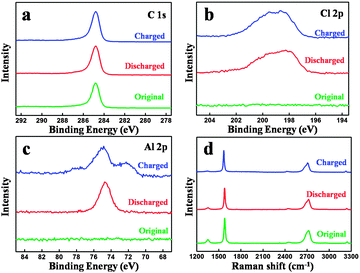
Fig. 4(a–c) show the XPS spectra of the original carbon paper and charged and discharged one in the 100th cycle. The C 1s XPS peaks of the original and cycled carbon paper remain unchanged, which demonstrates that the surface of the graphite is not involved during the charge and discharge process, matching with our assumption in Fig. 1 and TEM in Fig. 3. Slight differences can be seen in the Cl 2p XPS peaks, as shown in Fig. 4(b). However, the differences of Al 2p XPS peaks are obvious. After a charge process, a new peak appears, which can be attributed to the formation of a new kind of aluminium chloride, named AlxCly. After being charged, the cathode material is washed by alcohol under ultrasonic cleaning several times for the EDS test.
 | ||
| Fig. 4 XPS spectra of the original and cycled carbon paper: (a) C 1s, (b) Cl 2p and (c) Al 2p. (d) Raman spectra of the original and cycled carbon paper. | ||
EDS mapping images (Fig. S5, ESI†) also provide that Al and Cl elements intercalate into the graphite layers, matching with our assumption in Fig. 1. Fig. 4(d) shows the Raman spectra of the original carbon paper and charged and discharged carbon paper in the 20th cycle. Two peaks can be found at 1352 cm−1 (D band) and 1580 cm−1 (G band), respectively. The D band presents a disordered graphitic structure, whereas the G band corresponds to the crystallinity of graphite.23,24 Nearly no obvious differences can be found, which reveals that the structure of graphite before and after cycling is unchanged.
As discussed above, during the charge and discharge process, different from the behavior of a Li-ion battery, two single ions/coordination ions intercalate and deintercalate in the cathode, i.e., Al3+ and [AlaClb]−. As cathode material, carbon paper (composed of graphite) does not form common chemical bonds with the intercalated ions, only providing large space (graphite layers) for the intercalation and deintercalation of ions/coordination ions. After being intercalated in the graphite layers, the formed AlxCly is stored in neighboring graphite intercalating space by van der Waals' forces. As can be seen in Fig. 2(b), when discharged at 50 mA g−1, two discharge plateaus can be observed at 2.1–1.85 V (voltage stage I) and 1.85–1.52 V (voltage stage II), respectively, which is attributed to the simultaneous intercalation of Al3+ and [AlaClb]−. The voltage stage I agrees well with the c peak in the CV curves (Fig. 2(b)) while the voltage stage II accords with the a and b peaks in the CV curves (due to the extraordinary adjacency of the a and b peaks, the edge of the corresponding voltage plateaus are unconspicuous and ambiguous). Due to the big size of coordination ions and Al ions, the graphite layers are enlarged, which can be supported by the comparison of original and cycled carbon paper: (1) the volume expansion can be visually seen by experimental photographs in Fig. S1d (ESI†) and (2) the neighboring graphite intercalating space increases from 0.33 nm to 0.455 nm.
After tens of cycles, part of the graphite sheets crush into small pieces, and the surface of the Al foils is corroded, as shown in Fig. S6 (ESI†); however, the microstructure of the graphite remains unchanged. These results can be supported by TEM in Fig. 3 and Fig. S3 (ESI†) and XPS and Raman in Fig. 4. The unchanged graphite structure also proves that graphite does not form common chemical bonds with the intercalated ions.
It is worth noting that in the initial few cycles the discharge capacity gradually increases (Fig. 2(d)). These may be attributed to the following reasons: first, the graphite layers expand extremely during the intercalation of coordination ions, especially in the initial cycles. Then the volume adjustment occurs, which makes the graphite layers more suitable for the intercalation and deintercalation of coordination ions. Second, the simultaneously enlarged specific surface area of the cathode is in favor of the contact between the graphite and electrolyte. After several cycles, the capacity remains stable with nearly 100% coulombic efficiency (Fig. 2(d) and Fig. S2, ESI†), demonstrating a highly reversible charge and discharge process.
In summary, a new Al-ion battery has been proposed and established. A very high and obvious voltage plateau at ca. 1.8 V vs. Al3+/Al is achieved. As an Al-ion full battery, this is the first time that such a high voltage plateau has been reported. Even discharged at 100 mA g−1, the capacity can reach as high as 69.92 mA h g−1 over 100 cycles with high reversibility. Due to the low cost and abundance of raw materials (aluminium and graphite), the Al-ion battery established in this work shows bright prospect in the commercial application of Al-ion batteries. It is a creative work in the field of Al-ion batteries and will greatly promote the development of potential alternatives to lithium-ion batteries for electric energy storage.
This work was supported by the 111 Project (No. B13004)
Notes and references
- Z. Chen, Y. Ren, A. N. Jasen, C. Lin, W. Weng and K. Amine, Nat. Commun., 2013, 4, 1513 CrossRef PubMed.
- S. Tepavcevic, H. Xiong, V. R. Stamenkovic, X. Zuo, M. Balasubramanian, V. B. Prakapenka, C. S. Johnson and T. Rajh, ACS Nano, 2012, 6, 530–538 CrossRef CAS PubMed.
- F. Cheng, J. Liang, Z. Tao and J. Chen, Adv. Mater., 2011, 23, 1695–1715 CrossRef CAS PubMed.
- S. Nishimura, G. Kobayashi, K. Ohoyama, R. Kanno, M. Yashima and A. Yamada, Nat. Mater., 2008, 7, 707–711 CrossRef CAS PubMed.
- W. Wang, B. Jiang, W. Xiong, H. Sun, Z. Lin, L. Hu, J. Tu, J. Hou, H. Zhu and S. Jiao, Sci. Rep., 2013, 3, 3383 Search PubMed.
- N. Jayaprakash, S. K. Das and L. A. Archer, Chem. Commun., 2011, 47, 12610–12612 RSC.
- S. Liu, J. J. Hu, N. F. Yan, G. L. Pan, G. R. Li and X. P. Gao, Energy Environ. Sci., 2012, 5, 9743–9746 CAS.
- J. V. Rani, V. Kanakaiah, T. Dadmal, M. S. Rao and S. J. Bhavanarushi, J. Electrochem. Soc., 2013, 160, A1781–A1784 CrossRef CAS PubMed.
- N. S. Hudak, J. Phys. Chem. C, 2014, 118, 5203–5215 CAS.
- S. Liu, G. L. Pan, G. R. Li and X. P. Gao, J. Mater. Chem. A, 2015, 3, 959 CAS.
- Z. Li, K. Xiang, W. Xing, W. C. Carter and Y. Chiang, Adv. Energy Mater., 2015, 5, 1401410 Search PubMed.
- M. L. Doche, F. L. Cattin, R. Durand and J. J. Rameau, J. Power Sources, 1997, 65, 197–205 CrossRef CAS.
- C. Li, W. Ji, J. Chen and Z. Tao, Chem. Mater., 2007, 19, 5812–5814 CrossRef CAS.
- E. J. Rudd and D. W. Gibbons, J. Power Sources, 1994, 47, 329–340 CrossRef CAS.
- R. S. M. Patnaik, S. Ganesh, G. Ashok, M. Ganesan and V. Kapali, J. Power Sources, 1994, 50, 331–342 CrossRef CAS.
- Q. Li and N. J. Bjerrum, J. Power Sources, 2002, 110, 1–10 CrossRef CAS.
- P. Wasserscheid and W. Keim, Angew. Chem., Int. Ed., 2000, 39, 3772–3789 CrossRef CAS.
- F. Tuinstra and J. Koenig, J. Chem. Phys., 1970, 53, 1126 CrossRef CAS PubMed.
- P. Meduri, C. Pendyala, V. Kumar, G. U. Sumanasekera and M. K. Sunkara, Nano Lett., 2009, 9, 612–616 CrossRef CAS PubMed.
- A. C. Ferrari and J. Robertson, Philos. Trans. R. Soc. London, Ser. A, 2004, 362, 1824–2565 Search PubMed.
- L. F. Cui, R. Ruffo, C. K. Chan, H. Peng and Y. Cui, Nano Lett., 2009, 9, 491–495 CrossRef CAS PubMed.
- E. Hosono, H. Matsuda, I. Honma, S. Fujihara, M. Ichihara and H. Zhou, J. Power Sources, 2008, 182, 349–352 CrossRef CAS PubMed.
- G. S. Zakharova, C. Jahne, A. Popa, C. Täschner, T. Gemming, A. Leonhardt, B. Buchner and R. Klingeler, J. Phys. Chem. C, 2012, 116, 8714–8720 CAS.
- P. Poizot, S. Laruelle, S. Grugeon, L. Dupont and J. M. Tarascon, Nature, 2000, 407, 496–499 CrossRef CAS PubMed.
Footnote |
| † Electronic supplementary information (ESI) available: Experimental sections, experimental photographs, cycle performance and SEM images. See DOI: 10.1039/c5cc00542f |
| This journal is © The Royal Society of Chemistry 2015 |

