 Open Access Article
A sulphide resistant Ag|AgCl reference electrode for long-term monitoring†
David S.
Macedo
 *ab,
Mikko
Vepsäläinen
*c,
Theo
Rodopoulos
 a,
Stephen
Peacock
a and
Conor F.
Hogan
 b
b
aMineral Resources, CSIRO, Melbourne, Victoria 3168, Australia. E-mail: david.macedo@csiro.au; mikko.vepsalainen@vtt.fi
bDepartment of Biochemistry and Chemistry, La Trobe University, Melbourne, Victoria 3086, Australia
cTechnical Research Centre of Finland, VTT, Espoo, Finland
First published on 19th September 2024
Abstract
Reference electrodes which demonstrate long-term potential stability are essential for many continuous monitoring applications and are commonly based on Ag|AgCl electrodes; however, these electrodes are susceptible to poisoning from aqueous sulphide species which are commonly present in wastewater and natural groundwater. This work presents a sulphide resistant solid-state reference electrode (SSRE) based on a composite material using suspended KCl electrolyte and sacrificial AgCl in a cross-linked polyvinyl acetate polymer matrix. Sulphidation of the sacrificial AgCl produces a stable Ag2S precipitate and prevents further ingress of the poisoning sulphide species through the composite material. A novel SSRE using this material is compared to a control SSRE without suspended AgCl and a typical liquid filled reference electrode. These three reference electrodes are studied using electrochemical impedance spectroscopy (EIS), and their application is also studied in potentiometric pH sensing and cyclic voltammetry (CV). The long-term sulphide resistance of the two SSREs is also studied with potentiometry, and cross-sections of these electrodes were examined using micro X-ray fluorescence (μXRF). Both SSREs demonstrated higher impedance than the liquid reference electrode but were similar to other SSREs reported in the literature. This impedance did not result a meaningful difference in potentiometric pH sensing or CV experiments done using typical scan rates. The KCl/AgCl SSRE exhibited remarkable sulphide resistance, with all samples demonstrating a stable potential without maintenance after ca. 120 days of continuous immersion in 1 g L−1 Na2S solution, whereas KCl SSRE samples all demonstrated significant drift before this time. μXRF sulphur maps revealed that suspended AgCl prevented sulphide ingress, thus protecting the embedded Ag|AgCl electrode. This work presents a reference electrode that could enable long-term monitoring in challenging sulphide solutions, and also highlights a novel approach for preventing reference electrode poisoning which could be more widely explored.
Introduction
Reference electrodes are needed in most electroanalytic applications, ideally proving a stable reference for the measurement of indicator or working electrode potentials. There are numerous mercury and silver based reference electrodes for aqueous systems, but Ag|AgCl reference electrodes are most commonly used as the materials are inexpensive and relatively safe.1 The potential of these reference electrodes is dependent on the chloride activity at the internal Ag|AgCl electrode as described by the Nernst equation,2 and has the following half-cell reaction:| Ag(s) + Cl−(aq) ⇌ AgCl(s) + e− |
Drift in reference electrode potential is therefore often caused by chloride electrolyte leakage, however another source of instability is contamination of the Ag|AgCl electrode by chemical interferants such as hydroxide or sulphide species.3
Typical liquid-filled reference electrodes provide adequate performance in most laboratory applications, however there is an ongoing need for new designs which can withstand harsher chemical and physical conditions. In particular, in situ environmental monitoring relies on having sensors which require minimal maintenance or calibration,4–7 otherwise their use becomes less attractive compared to laborious sampling and laboratory analysis methods. For electrochemical sensors the reference electrode is often a limiting factor in online monitoring,8 especially for potentiometric sensors where the indicator electrode potential is directly used to determine analyte concentration.
Solid state reference electrodes (SSREs), constructed without an internal liquid reservoir, have proved to be an effective approach to making a more robust reference electrode. Since the earliest reports of SSREs in the late 1990s,9,10 numerous examples have since been reported in the literature including many polymer/electrolyte composite reference electrodes,11–13 and printed reference electrodes.14–17 Other recent reference electrode designs include a self-referencing pulstrode which relies on periodically reducing a AgI coating and using the resulting electromotive force as a reference,18,19 and capillary based electrodes which prevent contamination by using low flow rates and small sample volumes.20,21 It is clear from the wide array of designs that it is perhaps impossible to create an ideal reference electrode suitable for every condition, and therefore specifically tailored options are needed for each use case.
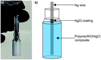
Sulphide species are often found in wastewater and natural groundwater,22–24 making poisoning an ongoing challenge for electrochemical sensors in these environments. Sulphidation of AgCl to form Ag2S has been widely reported in the literature,25–28 with the later material demonstrating a low solubility product and therefore great stability.29 Previously we reported a SSRE which demonstrated a continuous working lifetime of 175 days without maintenance in 1 M Na2SO4 solution.30 In this work we build on this design exploiting the creation of the aforementioned stable metal sulphide to create a sulphide resistant reference electrode. Sacrificial AgCl is suspended with KCl electrolyte and results in the precipitation of aqueous sulphide species as Ag2S before they can diffuse through the polymer matrix and contaminate the Ag|AgCl electrode (see Fig. 1). This simple design can be used similarly to other existing reference electrodes without a need for significant changes in electronics or incorporation of liquid sampling equipment. Electrochemical impedance spectroscopy (EIS) is used to study the KCl/AgCl SSRE, with comparisons to our previous KCl SSRE and a commercial liquid filled reference electrode. These three reference electrodes are also compared in two applications: potentiometric sensing with a glass pH electrode, and cyclic voltammetry (CV) experiments using [Ru(NH3)6]Cl3. Finally, the long-term sulphide resistance of both SSREs is studied using potentiometry and micro X-ray fluorescence (μXRF).
Experimental
Materials
Silver wire (99.9%) was purchased from A&E Metals. Vinyl acetate (99%), ethylene glycol dimethacrylate (EGDMA) (98%), and Na2S (98%) were supplied by Aldrich. KCl (99.8%) and glass chromatography vials were supplied by Thermo Fischer Scientific. AgCl (99.9%) was supplied by Alfa Aesar. 2,2′-Azobis(2-methylpropionitrile) (AIBN) (98%) was supplied by Acros Organics. pH buffers were supplied by Merck. [Ru(NH3)6]Cl3 (99%) was supplied by Strem Chemicals. Insulated copper wires, crimps, and heat shrink tubing were purchased from RS Components. The liquid reference electrode used for comparisons in EIS, potentiometric, and CV experiments was a saturated KCl Ag|AgCl (1004 Series, Koslow).Electrode preparation
Physical characterisation
Electrochemical measurements
Results and discussion
Impedance characterisation
The impedance of a reference electrode is an important parameter in determining the noise of an electrochemical experiment and the electrode's suitability for various electroanalytical techniques. To investigate the effect of suspended AgCl particles on electrode impedance, EIS was used to study both SSREs and compared to a typical liquid reference electrode, as shown in Fig. 2. These impedance values correspond to the same reference electrodes used for the potentiometric and voltammetric experiments presented later, however EIS was also repeated with replicate SSRE samples (see Fig. S2†). Each reference electrode demonstrated a mostly flat frequency response in the Bode plots, however higher impedance samples demonstrated larger phase angles in the high frequency range indicating a slowed voltage response.31 The mean impedance and standard deviation (n = 3) at 1.04 kHz were 16.3 ± 24.4 kΩ and 71.0 ± 51.7 kΩ for KCl and KCl/AgCl SSREs respectively. The large variability of impedance between electrodes of both SSREs may be due to differences in salt packing in the polymer matrix and Ag|AgCl wire positioning, however as it has been reported that most ionic conductivity in AgCl films occurs through micro-channels it may be expected that suspended AgCl particles in the polymer matrix will lower the conductivity of the material.32 All SSREs demonstrated impedances larger than those typically seen in liquid reference electrodes as the polymer matrix likely inhibits ionic conductivity, but these results are comparable to other resistance/impedance values reported for aqueous SSREs15,30 and lower than some reported ionic liquid based examples.3,33,34 The high impedance of these SSREs is likely to limit their use in fast CV and EIS because of noise and inductive effects respectively,31,35 but as we will show they provide comparable performance in potentiometry and CV experiments done at typical scan rates.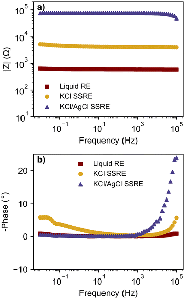 | ||
| Fig. 2 Bode plots with (a) magnitude of impedance and (b) phase angle; comparing a liquid RE, KCl SSRE, and KCl/AgCl SSRE. | ||
Applications – potentiometric sensing and cyclic voltammetry
To compare the stability each reference electrode and demonstrate their use with a high impedance indicator electrode, each reference electrode was paired with a glass pH electrode and tested in a series of pH buffers, as summarised in Fig. 3 and Table 1.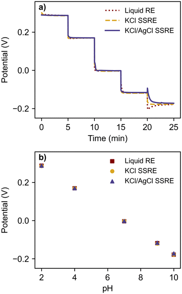 | ||
| Fig. 3 (a) open circuit potentiometry with glass pH electrode in a series of pH buffers using a liquid RE, KCl SSRE, and KCl/AgCl SSRE, and (b) the resulting calibration curve. | ||
| Reference electrode | Slope (mV pH−1) | Intercept (mV) | R 2 |
|---|---|---|---|
| Liquid | −58.0 | 402.4 | >0.9999 |
| KCl SSRE | −57.8 | 401.2 | >0.9999 |
| KCl/AgCl SSRE | −57.4 | 400.7 | >0.9999 |
Despite large differences in impedance, each reference electrode demonstrated equivalent performance, returning the expected linear calibration curves with similar Nernstian slopes and zero-point potentials.36 The signal noise was less than 0.2 mV for all reference electrodes and buffer solutions. Transient spikes were seen in pH 10 buffer tests when using the liquid reference electrode and the KCl/AgCl SSRE, likely a result of rinsing and wiping the electrodes between buffer solutions rather than an effect of reference electrode impedance. These results demonstrate that the KCl/AgCl SSREs provided a stable reference potential across a wide pH range and would be suitable for use with a large range of indicator electrodes for potentiometric experiments, even those with high impedance.
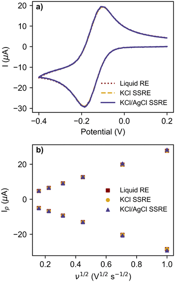
The reference electrodes were also compared in CV experiments using the commonly used redox probe [Ru(NH3)6]Cl3 at scan rates between 25 mV s−1 and 1 V s−1, as summarised in Fig. 4 and Table 2. The greater impedance of the KCl/AgCl SSRE did result in more signal noise compared to the other reference electrodes (Fig. S3–S5†), however this did not create significant differences in the analysis, even at the fastest scan rate of 1 V s−1 as seen in the voltammogram in Fig. 4a. Peak heights for the return peak were measured using a previous reported method of fitting a baseline to the diffusional current decay,37 and showed good agreement between each reference electrode, demonstrating that near equivalent performance was achieved across the entire range of scan rates. The linear regression results for these peak currents vs. square root of scan rate in Fig. 4b all demonstrated similar linearity, anodic, and cathodic slopes. Consequently, the diffusion coefficients calculated using these slopes with the Randles–Sevcik equation are all similar and close to previously reported values in the literature.38–41 These results demonstrate that the KCl/AgCl SSRE demonstrated comparable performance to a commercial liquid reference electrode, and should also prove suitable for chronoamperometric experiments. It should also be added that these datasets were analysed without any smoothing or post processing, however this may be useful in scenarios with a lower ratio of signal to noise.
| Reference electrode | Delta Ep range (mV) | Cathodic slope (μA s1/2 V−1/2) | Cathodic R2 | Anodic slope (μA s1/2 V−1/2) | Anodic R2 | [Ru(NH3)6]3+D (cm2 s−1) | [Ru(NH3)6]2+D (cm2 s−1) |
|---|---|---|---|---|---|---|---|
| Liquid | 77–87 | −28.757 | 0.9997 | 27.952 | 0.9998 | 7.41 × 10⁻⁶ | 7.00 × 10⁻⁶ |
| KCl SSRE | 76–84 | −28.757 | 0.9997 | 27.935 | 0.9998 | 7.41 × 10⁻⁶ | 6.99 × 10⁻⁶ |
| KCl/AgCl SSRE | 77–83 | −29.384 | 0.998 | 28.575 | 0.9998 | 7.74 × 10⁻⁶ | 7.32 × 10⁻⁶ |
Long-term sulphide resistance
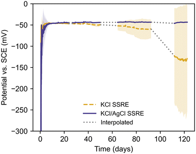
To demonstrate the benefits of AgCl additive in the composite matrix, KCl SSREs and KCl/AgCl SSREs were immersed in a pH 9 buffer solution with 1 g L−1 Na2S and left to condition in situ while their potentials were monitored vs. a SCE reference electrode, as summarised in Fig. 5 and Table 3. This solution was chosen to achieve sulphide concentrations well in excess of those typically found in wastewater systems and demonstrate the robustness of the KCl/AgCl composite SSRE.6,24 The pH buffer was used to prevent losses as H2S over time, making HS− the dominant sulphur species in these tests.42| Reference electrode | Stabilisation time (days) | Failure time (days) | Working time (days) |
|---|---|---|---|
| KCl SSRE | 2.0 ± 1.1 | 71.0 ± 25.1 | 69.1 ± 24.6 |
| KCl/AgCl SSRE | 3.1 ± 2.3 | N/A | >119.4 ± 2.3 |
The SSREs were all monitored simultaneously against the same SCE reference electrode, and the literature value of −47 mV vs. SCE at 25 °C was used to determine stabilisation and failure times.43 Each SSRE was considered to have stabilised once their potential was within 5 mV of this value for 2 hours, and the failure time was recorded as the first time the potential deviated from this range after stabilisation. The working time was calculated as the difference between the last measurement before failure and the stabilisation time. Every SSRE adopted a potential within 2 mV of the literature value after stabilisation, however the KCl SSREs demonstrated varying stability with some exhibiting a negative potential drift before 20 days (Fig. S6†). These results demonstrate how sulphide species can significantly shorten the working life of a reference electrode as samples using this composite previously demonstrated a working life greater than 175 days in 1 M Na2SO4 solution without any electrode failures.30 In contrast, no KCl/AgCl SSREs demonstrated this negative drift after stabilisation, and at ca. 120 days none had failed and all potentials were still close to the literature value (Fig. S7†). As such the variation in working time for KCl/AgCl SSREs in Table 3 is purely a result of differences in stabilisation time. Indeed, these electrodes were more stable in this environment than the commercial SCE used, which required consistent maintenance and occasional replacement due to poisoning over the course of the experiment. For this reason, affected periods of data have been omitted. It should be noted that the SSRE samples were continuously immersed during the entire experiment.
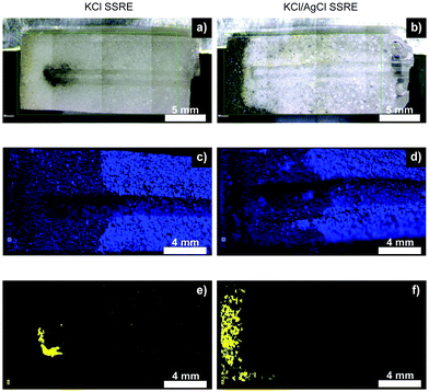
Fig. 6 summarises the results of μXRF studies on cross-sections of SSREs after sulphide testing, and illustrates how suspended AgCl captures sulphide species and prevents reference electrode poisoning. The μXRF distribution maps showed little difference in chlorine distribution between the two types of SSRE, suggesting a similar level of electrolyte loss. However, these experiments revealed significant differences in sulphur distributions. For samples without AgCl suspended in the polymer, a dark precipitate formed around the tip of the embedded wire, whereas the KCl/AgCl samples had this precipitate concentrated at the open end of the polymer composite. This dark precipitate correlates with the sulphur distributions shown in μXRF mapping, suggesting the formation of Ag2S.25,26,28 Some signal was also seen correlating with the chlorine distribution, most notably when comparing Fig. 6c and e, suggesting the presence of trace sulphur impurities in the KCl. The low solubility product of Ag2S also suggests that once this precipitate is formed the concentration of any aqueous sulphur species which could further diffuse through the polymer will be low.29 These results demonstrate that the use of AgCl suspension could enable long-term continuous monitoring in high sulphide environments such as wastewater and groundwater. These cross-sections also demonstrate that although this design could be miniaturised, this will also result in a smaller electrolyte reservoir and would likely reduce the electrode's longevity.
Conclusions
A novel Ag|AgCl SSRE based on a KCl/AgCl polymer composite was developed which demonstrates exceptional long-term stability in challenging sulphide solutions. The impedance of the new SSRE was higher than a typical liquid filled reference electrode but comparable to other SSREs in the literature. This impedance was not limiting for potentiometric or voltammetric experiments and provided near-equivalent performance to the lower impedance liquid reference electrode. The KCl/AgCl SSREs demonstrated potentials close to the −47 mV vs. SCE expected from theory even after 120 days of continuous immersion in an aggressive sulphide solution, outlasting the KCl SSRE and commercial liquid RE without any maintenance. μXRF measurements of SSRE cross-sections supported the hypothesis that suspended AgCl particles in the composite trap sulphide species, preventing their ingress and eventual poisoning of the Ag|AgCl electrode. This reference electrode should enable long-term continuous monitoring in wastewater and groundwater applications where sulphide is an ongoing challenge. More broadly, this work highlights a new approach for improving reference electrode longevity by capturing the interferant ions which cause poisoning, and suggests that similar composite materials could be explored for a range of other applications.Author contributions
David S. Macedo: conceptualisation, methodology, formal analysis, investigation, writing – original draft, writing – review & editing, visualisation. Mikko Vepsäläinen: conceptualisation, methodology, writing – review & editing, supervision, project administration, visualisation. Theo Rodopoulos: writing – review & editing, supervision, visualisation. Stephen Peacock: formal analysis, visualisation. Conor F. Hogan: writing – review & editing, supervision, visualisation.Data availability
The data supporting this article have been included as part of the ESI.† The program and source code used for measuring return peak current in cyclic voltammetry experiments is available at https://github.com/davedavedavem/diffusional-fitter.Conflicts of interest
There are no conflicts to declare.Acknowledgements
This work was funded by the Commonwealth Scientific and Industrial Research Organisation (CSIRO). The authors thank Luda Malishev for her assistance in electrode preparation, and Matthew Glenn for his assistance in SEM imaging.References
- P. Spitzer and S. Wunderli, in Handbook of Reference Electrodes, Springer Berlin Heidelberg, 2013, p. 77 Search PubMed.
- H. Kahlert, in Electroanalytical Methods: Guide to Experiments and Applications, ed. F. Scholz, Springer Berlin Heidelberg, Berlin, Heidelberg, 2002, pp. 261–278 Search PubMed.
- B. K. Troudt, C. R. Rousseau, X. I. N. Dong, E. L. Anderson and P. Bühlmann, Anal. Sci., 2022, 38, 71–83 CrossRef CAS PubMed.
- M. Cuartero, Sens. Actuators, B, 2021, 334, 129635 CrossRef CAS.
- M. Cuartero and G. A. Crespo, Curr. Opin. Electrochem., 2018, 10, 98–106 CrossRef CAS.
- D. Despot, M. P. Fernández and M. Barjenbruch, Water, 2021, 13, 1876 CrossRef CAS.
- A. Moretti, H. L. Ivan and J. Skvaril, J. Water Process Eng., 2024, 60, 105061 CrossRef.
- P. Kruse, J. Phys. D: Appl. Phys., 2018, 51, 203002 CrossRef.
- K. Nagy, K. Eine and K. Syverud, J. Electrochem. Soc., 1997, 144, 143–144 CrossRef.
- H. J. Lee, U. S. Hong, D. K. Lee, J. H. Shin, H. Nam and G. S. Cha, Anal. Chem., 1998, 70, 3377–3383 CrossRef CAS.
- S. Gan, C. Liao, R. Liang, S. Du, L. Zhong, Y. Tang, T. Han, Y. Bao, Z. Sun, Y. Ma and L. Niu, ACS Meas. Sci. Au, 2022, 2, 568–575 CrossRef CAS PubMed.
- Y. M. Wu and L. C. Chen, in ISOEN 2019 – 18th International Symposium on Olfaction and Electronic Nose, Proceedings, Institute of Electrical and Electronics Engineers Inc., 2019.
- A. Lewenstam, B. Bartoszewicz, J. Migdalski and A. Kochan, Electrochem. Commun., 2019, 109, 106613 CrossRef CAS.
- M. Sophocleous and J. K. Atkinson, Sens. Actuators, A, 2017, 267, 106–120 CrossRef CAS.
- R. C. Dawkins, D. Wen, J. N. Hart and M. Vepsäläinen, Electrochim. Acta, 2021, 393, 139043 CrossRef CAS.
- M. Komoda, I. Shitanda, Y. Hoshi and M. Itagaki, Electrochem. Commun., 2019, 103, 133–137 CrossRef CAS.
- A. Moya, R. Pol, A. Martínez-Cuadrado, R. Villa, G. Gabriel and M. Baeza, Anal. Chem., 2019, 91, 15539–15546 CrossRef CAS PubMed.
- W. Gao, E. Zdrachek, X. Xie and E. Bakker, Angew. Chem., Int. Ed., 2019, 1–6 Search PubMed.
- W. Gao, X. Xie and E. Bakker, ACS Sens., 2020, 5, 313–318 CrossRef CAS PubMed.
- E. L. Anderson, B. K. Troudt and P. Bühlmann, ACS Sens., 2021, 6, 2211–2217 CrossRef CAS PubMed.
- E. E. A. Robinson, B. K. Troudt and P. Bühlmann, Anal. Chem., 2024, 96, 2236–2243 CrossRef CAS PubMed.
- Z. Miao, M. L. Brusseau, K. C. Carroll, C. Carreón-Diazconti and B. Johnson, Environ. Geochem. Health, 2012, 34, 539–550 CrossRef CAS PubMed.
- M. Ardelean, F. Manea, N. Vaszilcsin and R. Pode, Anal. Methods, 2014, 6, 4775–4782 RSC.
- M. Sherief and A. A. Hassan, Water, 2022, 14, 791 CrossRef CAS.
- E. Lombi, E. Donner, S. Taheri, E. Tavakkoli, Å. K. Jämting, S. McClure, R. Naidu, B. W. Miller, K. G. Scheckel and K. Vasilev, Environ. Pollut., 2013, 176, 193–197 CrossRef CAS PubMed.
- R. Kaegi, A. Voegelin, B. Sinnet, S. Zuleeg, H. Siegrist and M. Burkhardt, Sci. Total Environ., 2015, 535, 20–27 CrossRef CAS PubMed.
- C. Levard, E. M. Hotze, G. V. Lowry and G. E. Brown, Environ. Sci. Technol., 2012, 46, 6900–6914 CrossRef CAS PubMed.
- Y. Yin, W. Xu, Z. Tan, Y. Li, W. Wang, X. Guo, S. Yu, J. Liu and G. Jiang, Environ. Pollut., 2017, 220, 955–962 CrossRef CAS PubMed.
- S. Licht, J. Electrochem. Soc., 1988, 135, 2971–2975 CrossRef CAS.
- D. S. Macedo, M. Vepsäläinen, D. Acharya, C. D. Wood, D. Wen, L. Thomson, S. Peacock, T. Rodopoulos and C. F. Hogan, Electrochim. Acta, 2021, 368, 137636 CrossRef CAS.
- A. C. Lazanas and M. I. Prodromidis, ACS Meas. Sci. Au, 2023, 3, 162–193 CrossRef CAS PubMed.
- H. Ha and J. Payer, Electrochim. Acta, 2011, 56, 2781–2791 CrossRef CAS PubMed.
- X. V. Chen, A. Stein and P. Bühlmann, ACS Sens., 2020, 5, 1717–1725 CrossRef CAS PubMed.
- T. M. Galiullin, N. V. Pokhvishcheva, A. V. Kalinichev and M. A. Peshkova, Electroanalysis, 2019, 31, 1708–1718 CrossRef CAS.
- T. J. Smith and K. J. Stevenson, in Handbook of Electrochemistry, Elsevier, 2007, pp. 73–110 Search PubMed.
- A. Beard, M.-T. Gmbh, S. Delina, J. Mettler-Toledo, S. Schmidt and H. Galster, Ullmann's Encycl. Ind. Chem., 2023, 1–39 Search PubMed.
- D. S. Macedo, T. Rodopoulos, M. Vepsäläinen, S. Bajaj and C. F. Hogan, Anal. Chem., 2024, 96, 1530–1537 CrossRef CAS PubMed.
- Y. Wang, J. G. Limon-Petersen and R. G. Compton, J. Electroanal. Chem., 2011, 652, 13–17 CrossRef CAS.
- Á. Molina, E. Laborda, E. I. Rogers, F. Martínez-Ortiz, C. Serna, J. G. Limon-Petersen, N. V. Rees and R. G. Compton, J. Electroanal. Chem., 2009, 634, 73–81 CrossRef.
- T. L. Ferreira, T. R. L. C. Paixão, E. M. Richter, O. A. El Seoud and M. Bertotti, J. Phys. Chem. B, 2007, 111, 12478–12484 CrossRef CAS PubMed.
- K. J. Levey, M. A. Edwards, H. S. White and J. V. Macpherson, Phys. Chem. Chem. Phys., 2023, 25, 7832–7846 RSC.
- A. E. Lewis, Hydrometallurgy, 2010, 104, 222–234 CrossRef CAS.
- A. J. Bard, L. R. Faulkner and H. S. White, Electrochemical Methods: Fundamentals and Applications, John Wiley & Sons, Ltd, 3rd edn, 2022 Search PubMed.
Footnote |
| † Electronic supplementary information (ESI) available. See DOI: https://doi.org/10.1039/d4an01076k |
| This journal is © The Royal Society of Chemistry 2024 |

